
Related Manuals for Cognex In-Sight D905


Summary of Contents for Cognex In-Sight D905
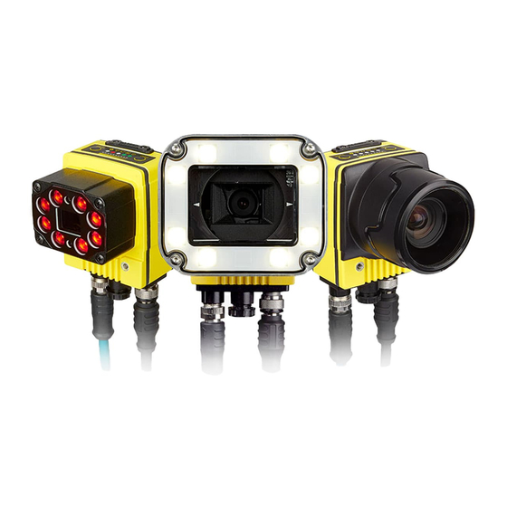
- Page 1 ® In-Sight D900 Series Vision System Reference Guide 2020 April 29 Revision: 1.2.0.1...
-
Page 2: Legal Notices
Copyright © 2020. Cognex Corporation. All Rights Reserved. Portions of the hardware and software provided by Cognex may be covered by one or more U.S. and foreign patents, as well as pending U.S. and foreign patents listed on the Cognex web site at: cognex.com/patents. -
Page 3: Regulations And Conformity
Regulations and Conformity Regulations and Conformity Note: For the most current CE declaration and regulatory conformity information, see the Cognex support site: cognex.com/support. Safety and Regulatory Cognex Corporation Manufacturer One Vision Drive Natick, MA 01760 USA In-Sight D902: Regulatory Model 50118 In-Sight D905: Regulatory Model R00099 This is a class A product. -
Page 4: China Rohs
表示用于本部件的至少一种均质材料中所含的危害物质超过GB / T26572 - 2011 的限制要求。 For European Community Users Cognex complies with Directive 2012/19/EU OF THE EUROPEAN PARLIAMENT AND OF THE COUNCIL of 4 July 2012 on waste electrical and electronic equipment (WEEE). This product has required the extraction and use of natural resources for its production. It may contain hazardous substances that could impact health and the environment, if not properly disposed. -
Page 5: Precautions
Precautions Precautions To reduce the risk of injury or equipment damage when you install the Cognex product, observe the following precautions: The vision system requires a UL or NRTL listed power supply with a 24VDC output that meets the following rating requirements: At least 5A continuous current. -
Page 6: Table Of Contents
Table of Contents Table of Contents Legal Notices Regulations and Conformity China RoHS For European Community Users Precautions Table of Contents Symbols Introduction Support Standard Components Accessories In-Sight Lenses, Lights and Covers External Lights Cables Mounting Brackets Power Supplies Connectors and Indicators Installation Install the Lens, Lighting and Cover Install the C-Mount Lens and Cover (COV-7000-CMNT or COV-7000-CMNT-EX) - Page 7 Table of Contents D902 Vision System D905 Vision System D900 Series Vision System with Cover (COV-7000-CMNT) D900 Series Vision System with Cover (COV-7000-CMNT-EX) D900 Series Vision System with Cover (COV-7000-CMNT-LG) D900 Series Vision System with Cover (COV-7000-CMNT-LG) and Extender (COV-7000-CMNT-LGX) 76 D900 Series Vision System with Illumination (ISLM-7000-xxx) Mounting Bracket (BKT-INS-01) C-Mount Lens Clearance Dimensions...
-
Page 8: Symbols
Symbols Symbols The following symbols indicate safety precautions and supplemental information: WARNING: This symbol indicates a hazard that could cause death, serious personal injury or electrical shock. CAUTION: This symbol indicates a hazard that could result in property damage. Note: This symbol indicates additional information about a subject. Tip: This symbol indicates suggestions and shortcuts that might not otherwise be apparent. -
Page 9: Introduction
Vision Suite Help file. Standard Components Note: Cables are sold separately. If a standard component is missing or damaged, immediately contact your Cognex Authorized Service Provider (ASP) or Cognex Technical Support. Component Description Provides image acquisition, vision processing, job storage, Ethernet connectivity and discrete I/O. -
Page 10: Accessories
Introduction Accessories You can purchase the following components separately. For a list of options and accessories, contact your local Cognex sales representative. In-Sight Lenses, Lights and Covers The following In-Sight lenses, lights and covers are supported with the vision system. - Page 11 Introduction Accessory Part Number Accessory Image Metal C-Mount lens cover adapter. Compatible with the following ADPT-MTL-M55 In-Sight 5000 series metal C-Mount lens covers: LNS-CVR-EXT01 LNS-CVR-R-00 LNS-CVR-UV-00 LNS-CVR50-AL-2 Note: If using the ADPT-MTL-M55 lens cover adapter, the maximum lens diameter including locking screws is 58.5mm.
- Page 12 Introduction C-Mount Illumination Accessories Note: The vision system supports connecting an integrated illumination accessory to the vision system's faceplate and connecting an external light to the vision system's LIGHT connector, but does not support using both lighting devices simultaneously. When using a C-Mount lens, the following restrictions apply: Maximum thread length is 5.25mm.
- Page 13 Introduction Accessory Part Number Accessory Image Red LED ring light ISL-7000-RD IR LED ring light ISL-7000-IR Blue LED ring light ISL-7000-BL White LED ring light ISL-7000-WHI Red bandpass filter used with the ISL-7000-RD LED ring light ISF-7000-RDBP605 IR bandpass filter used with the ISL-7000-IR LED ring light ISF-7000-IRBP815 Blue bandpass filter used with the ISL-7000-BL LED ring light ISF-7000-BLBP435...
- Page 14 Introduction S-Mount/M12 Autofocus Accessories Note: The vision system supports connecting an integrated illumination accessory to the vision system's faceplate and connecting an external light to the vision system's LIGHT connector, but does not support using both lighting devices simultaneously. For the In-Sight D905, the vision system image circle is larger than the S-Mount/M12 lenses used in the autofocus module (ISAF-7000-8mm) and the S-Mount/M12 adapter kit (ISLN-7000-SMNT), resulting in mechanical vignetting in the image when using any S-Mount/M12 lens.
- Page 15 Introduction Accessory Part Number Accessory Image Red LED ring light ISL-7000-RD IR LED ring light ISL-7000-IR Blue LED ring light ISL-7000-BL White LED ring light ISL-7000-WHI Red bandpass filter used with the ISL-7000-RD LED ring light ISF-7000-RDBP605 IR bandpass filter used with the ISL-7000-IR LED ring light ISF-7000-IRBP815 Blue bandpass filter used with the ISL-7000-BL LED ring light ISF-7000-BLBP435...
-
Page 16: External Lights
Cognex power cable (IVSL-5PM12-5) can be used to connect the light to the separate power supply. Only the power and ground wires from the Cognex power cable (IVSL-5PM12-5) should be connected to the remote power supply. - Page 17 Introduction Accessory Part Number Supported External Light Cables Accessory Image IVSL-5PM12-J300 Bar light, wide red IVSL-YLW2X-625 IVSL-5PM12-J500 IVSL-5PM12-J1000 IVSL-5PM12-J2000 IVSL-5PM12-J300 Bar light, narrow red, linear IVSL-YLW2X-625P IVSL-5PM12-J500 polarizer IVSL-5PM12-J1000 IVSL-5PM12-J2000 IVSL-5PM12-J300 Bar light, narrow infrared IVSL-YLW2X-850 IVSL-5PM12-J500 IVSL-5PM12-J1000 IVSL-5PM12-J2000 IVSL-5PM12-J300 Bar light, narrow blue IVSL-YLW300-470 IVSL-5PM12-J500...
-
Page 18: Cables
Introduction Cables Note: If using an integrated or external illumination accessory, the 10 meter and 15 meter Breakout cables are not supported. When using the 15 meter Breakout cable, full 24VDC voltage must be maintained at the input leads of the Breakout cable when the vision system is operating. -
Page 19: Mounting Brackets
Mounting bracket with M3, M4 and 1/4 - 20 mounting holes. Mounting screws are not BKT-INS-01 included. The mounting bracket is supported with In-Sight 5000 series, In-Sight 7000 Gen2 series, In-Sight 9000 series and In-Sight D900 series vision systems. Power Supplies Accessory... -
Page 20: Connectors And Indicators
Introduction Connectors and Indicators Connector Function Connects the Breakout cable, which provides connections to an external power supply, the acquisition trigger input, general-purpose inputs and high-speed outputs. For more information, refer to Breakout Connector Cable on page 70. Connects the vision system to an external lighting device. For more information, refer to External Light LIGHT Connector on... -
Page 21: Installation
Installation Installation Read this section to learn how the vision system connects to its standard components and accessories. For a list of options and accessories, contact your Cognex sales representative. Note: Cables are sold separately. CAUTION: All cable connectors are keyed to fit the connectors on the vision system. Do not force the connections or damage may occur. - Page 22 Installation 5. Attach the cover to the vision system. Rotate the cover clockwise approximately seven degrees to lock it.
-
Page 23: Install The C-Mount Lens And Cover (Cov-7000-Cmnt-Lg)
Installation Install the C-Mount Lens and Cover (COV-7000-CMNT-LG) Complete the following steps to install a C-Mount lens and cover to the vision system. The C-Mount cover is an optional accessory and required for IP67 protection. Note: When using a C-Mount lens, the following restrictions apply: Maximum thread length is 5.25mm. -
Page 24: Install The C-Mount Lens And In-Sight Illumination
Installation Install the C-Mount Lens and In-Sight Illumination Complete the following steps to install a C-Mount lens and the illumination accessory (ISLM-7000-WHI). The illumination accessory (ISLM-7000-WHI) is an optional accessory and required for IP67 protection. Note: The vision system supports connecting an integrated illumination accessory to the vision system's faceplate and connecting an external light to the vision system's LIGHT connector, but does not support using both lighting devices simultaneously. - Page 25 Installation 3. Plug the PCB into the lighting connector on the vision system faceplate. CAUTION: If uninstalling the PCB from the vision system, refer to Remove the Illumination Accessory PCB on page 82 for steps to safely remove the PCB and avoid damage to the vision system. 4.
- Page 26 Installation 5. Thread the lens into the vision system. Focusing of the C-Mount lens prior to light housing installation is required. Note: If installing the autofocus module accessory (ISAF-7000-8mm), refer to Install the Autofocus Module and In-Sight Illumination on page 29. 6.
- Page 27 Installation 7. Optionally, install a bandpass filter to the light baffle. Tip: Wear gloves when installing the filter to prevent leaving fingerprints on the surface of the filter. a. Insert the filter in the light baffle so it is held in place between the light baffle's filter retention tabs. Both sides of the filter are the same;...
- Page 28 Installation 8. Install the light baffle. a. Tilt the light baffle toward the light housing and maneuver the light baffle past the top of the LED ring light structure. b. Compress the light baffle and maneuver the bottom of the light baffle past the bottom of the LED ring light structure until the light baffle snaps into place, with the keyed tabs sitting flush over each light housing captive screw access hole.
-
Page 29: Install The Autofocus Module And In-Sight Illumination
Installation Install the Autofocus Module and In-Sight Illumination Complete the following steps to install the autofocus module accessory (ISAF-7000-8mm) and illumination accessory (ISLM-7000-WHI). Note: The autofocus module has an 8mm M12 lens pre-installed. If a different lens is required, it should be installed into the autofocus module before the autofocus module is installed to the vision system. - Page 30 Installation 3. Plug the PCB into the lighting connector on the vision system faceplate. CAUTION: If uninstalling the PCB from the vision system, refer to Remove the Illumination Accessory PCB on page 82 for steps to safely remove the PCB and avoid damage to the vision system. 4.
- Page 31 Installation 5. Install the autofocus module. CAUTION: Do not hot-plug the autofocus module. Verify the vision system is not receiving power when connecting or disconnecting the autofocus module. Note: If a different lens is required, it should be installed in the autofocus module before the autofocus module is installed to the vision system.
- Page 32 Installation 6. Install the light housing. CAUTION: Do not hot-plug the LED ring light. Verify the vision system is not receiving power when connecting or disconnecting the LED ring light. A connector protrudes from the underside of the light housing. To prevent damage, it is recommended the light housing not be removed from the box until ready to be assembled.
- Page 33 Installation 7. Optionally, install a bandpass filter to the light baffle. Tip: Wear gloves when installing the filter to prevent leaving fingerprints on the surface of the filter. a. Insert the filter in the light baffle so it is held in place between the light baffle's filter retention tabs. Both sides of the filter are the same;...
- Page 34 Installation 8. Install the light baffle. a. Tilt the light baffle toward the light housing and maneuver the light baffle past the top of the LED ring light structure. b. Compress the light baffle and maneuver the bottom of the light baffle past the bottom of the LED ring light structure until the light baffle snaps into place, with the keyed tabs sitting flush over each light housing captive screw access hole.
-
Page 35: Install The S-Mount/M12 Manual Focus Lens
Installation Install the S-Mount/M12 Manual Focus Lens Complete the following steps to install an In-Sight S-Mount/M12 manual focus lens. The S-Mount/M12 adapter kit (ISLN- 7000-SMNT) is required when installing In-Sight S-Mount/M12 manual focus lenses. Note: The DataMan clear cover accessory (DM300-CLCOV) is supported with In-Sight S-Mount/M12 manual focus lenses and provides an IP65 rating. - Page 36 Installation 6. Thread the lens into the vision system. Focusing of lens prior to installation of the rubber lens-locking cone is required. 7. Place the 13mm or 14mm rubber lens-locking cone over the M12 lens until it snaps tightly into place around the nose of the lens.
-
Page 37: Working Distance And Field Of View (S-Mount/M12 Lenses)
Installation Working Distance and Field of View (S-Mount/M12 Lenses) The working distance is the distance from the In-Sight illumination accessory cover (ISLM-7000-xxx) to the part that needs to be inspected. Field of view is what the vision system can see at that distance. As the working distance increases, so does the size of the field of view. -
Page 38: Mount The Vision System
Installation Mount the Vision System The vision system provides mounting holes for attachment to a mounting surface. Note: In the rear housing, the maximum insertion depth of the M4 screws should not exceed 8mm. This does not include the thickness of the mounting material used. In the front housing, the maximum insertion depth of the M4 screws closest to the lens should not exceed 3mm and the M4 screws closest to the connectors should not exceed 4.5mm. -
Page 39: Install The Mounting Bracket (Bkt-Ins-01)
Installation Install the Mounting Bracket (BKT-INS-01) Complete the following steps to attach the accessory mounting bracket (BKT-INS-01) to the vision system. Note: When attaching the vision system to the mounting bracket: If using the M4 screw holes, the thread length of the M4 screw should not exceed 12mm. If using the 1/4 - 20 screw holes, the thread length of the screw should not exceed 10mm. -
Page 40: Connect The External Light Cable (Optional)
Installation Connect the External Light Cable (Optional) The vision system's LIGHT connector is used to connect the External Light cable to an external lighting device, providing power and strobe control. The External Light cable can be connected to either a continuous or strobed lighting device. For a list of supported accessories, refer to External Lights on page 16. -
Page 41: Connect The Ethernet Cable
Installation Connect the Ethernet Cable CAUTION: The Ethernet cable shield must be grounded at the far end. Whatever this cable is plugged into (typically a switch or router) should have a grounded Ethernet connector. A digital voltmeter should be used to validate the grounding. -
Page 42: Connect The Breakout Cable
Installation Connect the Breakout Cable CAUTION: To reduce emissions, connect the far end of the Breakout cable shield to frame ground. Note: Perform wiring or adjustments to I/O devices when the vision system is not receiving power. You can cut exposed wires short or trim wire ends. You also can tie the wires back if you use a tie made of non-conductive material. -
Page 43: Replace The Sd Card (Optional)
Installation Replace the SD Card (Optional) The vision system is equipped with a Micro SD card slot and an 8GB SD card is pre-installed for saving job and image files. Complete the following steps to replace the pre-installed SD card. Note: The vision system supports: SDHC cards with a maximum capacity of 32GB, formatted with a FAT32 file system. -
Page 44: Replace The Led Ring Light (Optional)
Installation Replace the LED Ring Light (Optional) The illumination accessory (ISLM-7000-WHI) has a white LED ring light pre-installed. Complete the following steps to replace the pre-installed LED ring light. CAUTION: Do not hot-plug the illumination accessory. Verify the vision system is not receiving power when connecting or disconnecting the illumination accessory. - Page 45 Installation 3. Remove the keyed light baffle. Note: This step includes an optional bandpass filter accessory installed to the light baffle. For more information, refer to In-Sight Lenses, Lights and Covers on page 10. 4. The LED ring light screw holes are indicated by a triangle symbol ►. Use a 2mm hex wrench to remove the four M2.5 x 6mm screws and remove the LED ring light from the light housing.
- Page 46 Installation 5. Install the new LED ring light. CAUTION: Do not hot-plug the LED ring light. Verify the vision system is not receiving power when connecting or disconnecting the LED ring light. a. Place the new LED ring light inside the light housing, with "TOP" oriented upward. b.
- Page 47 Installation 6. Install the light baffle. a. Tilt the light baffle toward the light housing and maneuver the light baffle past the top of the LED ring light structure. b. Compress the light baffle and maneuver the bottom of the light baffle past the bottom of the LED ring light structure until the light baffle snaps into place, with the keyed tabs sitting flush over each light housing captive screw access hole.
- Page 48 Installation 7. Install the cover. a. Place the cover on the light housing. b. Align the central clear region of the cover with the light baffle edges. c. Insert the four M3 x 12mm screws and use a 2mm hex wrench to torque screws to 0.31 Nm (2.75 in-lb). 8.
-
Page 49: Replace The M12 Autofocus Lens (Optional)
Installation Replace the M12 Autofocus Lens (Optional) The autofocus module accessory (ISAF-7000-8mm) has an 8mm M12 lens pre-installed. Complete the following steps to replace the pre-installed M12 lens. Note: For the In-Sight D905, the vision system image circle is larger than the S-Mount/M12 lenses used in the autofocus module (ISAF-7000-8mm) and the S-Mount/M12 adapter kit (ISLN-7000-SMNT), resulting in mechanical vignetting in the image when using any S-Mount/M12 lens. - Page 50 Installation 3. Use a 2mm hex wrench to remove the four M3 x 12mm screws and remove the cover. 4. Remove the keyed light baffle. Note: This step includes an optional bandpass filter accessory installed to the light baffle. For more information, refer to In-Sight Lenses, Lights and Covers on page 10.
- Page 51 Installation 5. The light housing contains four captive screws that are accessible via captive screw access holes in the LED ring light board. Use a 2mm hex wrench to loosen the four captive screws and remove the light housing. CAUTION: Do not hot-plug the LED ring light. Verify the vision system is not receiving power when connecting or disconnecting the LED ring light.
- Page 52 Installation 7. Remove the M12 lens from the autofocus module. a. Remove the blue threaded lens nut on the underside of the autofocus module. b. Remove the M12 lens from the autofocus module.
- Page 53 Installation 8. Install the new M12 lens. a. An extra black lens nut is included with the lens toolkit accessory (ISAF-7000-TOOL). Thread this black lens nut on the new M12 lens until snug. b. Drop the new M12 lens into the module. c.
- Page 54 Installation e. With the lens tool, apply just enough pressure on the front of the lens to prevent the lens from moving. With the chamfer side of the blue lens nut facing the module, screw the blue nut onto the back of the lens. Once the threads of the blue nut are engaged with the lens, remove the lens tool and continue threading the blue nut until it is snug against the focus mechanism.
- Page 55 Installation 10. Install the light housing. CAUTION: Do not hot-plug the LED ring light. Verify the vision system is not receiving power when connecting or disconnecting the LED ring light. A connector protrudes from the underside of the light housing and can be damaged if placed on a hard surface.
- Page 56 Installation 11. Install the light baffle. Note: This step includes an optional bandpass filter accessory installed to the light baffle. For more information, refer to In-Sight Lenses, Lights and Covers on page 10. a. Tilt the light baffle toward the light housing and maneuver the light baffle past the top of the LED ring light structure.
- Page 57 Installation 12. Install the cover. a. Place the cover on the light housing. b. Align the central clear region of the cover with the light baffle edges. c. Insert the four M3 x 12mm screws and use a 2mm hex wrench to torque screws to 0.31 Nm (2.75 in-lb). 13.
-
Page 58: Specifications
Specifications Specifications The following sections list general specifications for the vision system. D902 Vision System Specifications Specifications D902 Minimum Firmware In-Sight version 2.2.0. Requirement Job/Program Memory 16GB non-volatile flash memory; unlimited storage via remote network device. Image Processing 3GB SDRAM Memory 1 Micro SD card slot with an 8GB SD card pre-installed for saving job and image files. - Page 59 Specifications Specifications D902 In-Sight Illumination Cover is compliant with ANSI Z87.1-2003 Drop-Ball Impact Test (no fracture, 25.4mm Accessory diameter steel ball, vertical drop from 127cm). (ISLM-7000-xxx) In-Sight Autofocus Number of Focus Cycles: 20,000 Module Accessory (ISAF-7000-8mm) Network 1 Ethernet port, 10/100/1000 BaseT with auto MDIX. IEEE 802.3 TCP/IP Protocol. Supports Communication DHCP, static and link-local IP address configuration.
- Page 60 Specifications Specifications D902 Protection IP67 with all cables properly attached (or the provided connector plug installed), the IP67- rated cover properly installed, and the Micro SD card cover fastened in place. Shock (Shipping and IEC 60068-2-27: 18 shocks (3 shocks in each polarity in each (X, Y, Z) axis) 80 Gs (800m/s Storage) 11ms, half-sinusoidal) with cables or cable plugs and a 150 gram or lighter lens attached.
-
Page 61: D905 Vision System Specifications
Specifications D905 Vision System Specifications Specifications D905 Minimum Firmware In-Sight version 2.2.0. Requirement Job/Program Memory 16GB non-volatile flash memory; unlimited storage via remote network device. Image Processing 3GB SDRAM Memory 1 Micro SD card slot with an 8GB SD card pre-installed for saving job and image files. The SD Card vision system supports: SDHC cards with a maximum capacity of 32GB, formatted with a FAT32 file system. - Page 62 Specifications Specifications D905 In-Sight Autofocus Number of Focus Cycles: 20,000 Module Accessory Note: For the In-Sight D905, the vision system image circle is larger than the S- (ISAF-7000-8mm) Mount/M12 lenses used in the autofocus module (ISAF-7000-8mm) and the S- Mount/M12 adapter kit (ISLN-7000-SMNT), resulting in vignetting in the image when using any S-Mount/M12 lens.
- Page 63 Specifications Specifications D905 Protection IP67 with all cables properly attached (or the provided connector plug installed), the IP67- rated cover properly installed, and the Micro SD card cover fastened in place. Shock (Shipping and IEC 60068-2-27: 18 shocks (3 shocks in each polarity in each (X, Y, Z) axis) 80 Gs (800m/s Storage) 11ms, half-sinusoidal) with cables or cable plugs and a 150 gram or lighter lens attached.
-
Page 64: Acquisition Trigger Input
Specifications Acquisition Trigger Input The vision system features one acquisition trigger input, which is optically isolated. You can configure the acquisition trigger input to trigger from an NPN (current sinking) or PNP (current sourcing) device. Specification Description ON: 15 to 28V DC (24DC nominal) Voltage OFF: 0 to 5VDC (11.5VDC nominal threshold) ON: 2.6mA to 4.9mA from 15 to 28V input... -
Page 65: General-Purpose Inputs
Specifications General-Purpose Inputs The vision system features three built-in general-purpose inputs, which are optically isolated. The inputs can be configured as either NPN (current sinking) or PNP (current sourcing) lines. Specification Description ON: 15 to 28V DC (24DC nominal) Voltage OFF: 0 to 5VDC (11.5VDC nominal threshold) ON: 2.6mA to 4.9mA from 15 to 28V input Current (Typical) -
Page 66: High-Speed Outputs
Specifications High-Speed Outputs The vision system features four built-in, high-speed outputs, which are optically isolated. The high-speed outputs can be used as either NPN (current sinking) or PNP (current sourcing) lines. Specification Description Voltage 26.4VDC maximum through external load Current 50mA maximum sink or source current OFF state leakage current 100µA External load resistance 470 Ohms to 10K Ohms... -
Page 67: High-Speed Output Wiring
Specifications High-Speed Output Wiring To connect to an NPN-compatible PLC input, connect one of the vision system's high-speed outputs directly to the PLC input. When enabled, the output pulls the PLC input down to less than 3VDC. To connect to a PNP-compatible PLC input, connect one of the vision system's high-speed outputs directly to the PLC input. -
Page 68: External Light Connector
Specifications External Light Connector The vision system's LIGHT connector is used to connect the External Light cable to an external lighting device, providing power and strobe control. The External Light cable can be connected to either a continuous or strobed lighting device. Before using an external lighting device, you must configure the light settings within the In-Sight Vision Suite software. -
Page 69: Ethernet Cable
Specifications Ethernet Cable The Ethernet cable provides Ethernet connectivity to the vision system. P1 Pin Number Wire Color Signal Name P2 Pin Number White/Orange TxRx A + Orange TxRx A - White/Green TxRx B + Blue TxRx C + White/Blue TxRx C - Green TxRx B -... -
Page 70: Breakout Cable
Specifications Breakout Cable The Breakout cable provides connections to an external power supply, the acquisition trigger input, general-purpose inputs and high-speed outputs. The Breakout cable is not terminated. Wire Color Pin# Signal Names IN 2 / HSOUT 2 Yellow UNUSED White/Yellow UNUSED Brown... -
Page 71: Dimensions
Specifications Dimensions The following sections list dimensions of the vision system and optional accessories. D902 Vision System Note: Dimensions are in millimeters [inches] and are for reference purposes only. All specifications are for reference purposes only and can change without notice. -
Page 72: D905 Vision System
Specifications D905 Vision System Note: Dimensions are in millimeters [inches] and are for reference purposes only. All specifications are for reference purposes only and can change without notice. -
Page 73: D900 Series Vision System With Cover (Cov-7000-Cmnt)
Specifications D900 Series Vision System with Cover (COV-7000-CMNT) Note: Dimensions are in millimeters [inches] and are for reference purposes only. All specifications are for reference purposes only and can change without notice. -
Page 74: D900 Series Vision System With Cover (Cov-7000-Cmnt-Ex)
Specifications D900 Series Vision System with Cover (COV-7000-CMNT-EX) Note: Dimensions are in millimeters [inches] and are for reference purposes only. All specifications are for reference purposes only and can change without notice. -
Page 75: D900 Series Vision System With Cover (Cov-7000-Cmnt-Lg)
Specifications D900 Series Vision System with Cover (COV-7000-CMNT-LG) Note: Dimensions are in millimeters [inches] and are for reference purposes only. All specifications are for reference purposes only and can change without notice. -
Page 76: D900 Series Vision System With Cover (Cov-7000-Cmnt-Lg) And Extender (Cov-7000-Cmnt-Lgx)
Specifications D900 Series Vision System with Cover (COV-7000-CMNT-LG) and Extender (COV-7000-CMNT-LGX) Note: Dimensions are in millimeters [inches] and are for reference purposes only. All specifications are for reference purposes only and can change without notice. -
Page 77: D900 Series Vision System With Illumination (Islm-7000-Xxx)
Specifications D900 Series Vision System with Illumination (ISLM-7000-xxx) Note: Dimensions are in millimeters [inches] and are for reference purposes only. All specifications are for reference purposes only and can change without notice. -
Page 78: Mounting Bracket (Bkt-Ins-01)
Specifications Mounting Bracket (BKT-INS-01) Note: Dimensions are in millimeters [inches] and are for reference purposes only. All specifications are for reference purposes only and can change without notice. -
Page 79: C-Mount Lens Clearance Dimensions
Specifications C-Mount Lens Clearance Dimensions Note: When using a C-Mount lens, the following restrictions apply: Maximum thread length is 5.25mm. The C-Mount lens threads and body cannot protrude more than 6.5mm in length into the vision system when screwed in unless the diameter of the back lens is smaller than 14.75mm. If the C- Mount lens threads and body protrude more than 6.5mm, you can add a spacer between the lens and vision system. -
Page 80: Cleaning/Maintenance
Cleaning/Maintenance Cleaning/Maintenance Clean the Housing To clean the outside of the vision system housing, use a small amount of mild detergent cleaner or isopropyl alcohol on a cleaning cloth. Do not pour the cleaner on the vision system housing. CAUTION: Do not attempt to clean any In-Sight product with harsh or corrosive solvents, including lye, methyl ethyl ketone (MEK) or gasoline. -
Page 81: Appendix
Appendix Appendix Mechanical Vignetting All lenses are designed to cover a certain “image circle” size, which can be found in the lens manufacturer’s specification. The image circle size is the diameter of the optical image the lens can produce. If a vision system has 2/3” image sensor, you must use a lens that produces at least a 2/3”... -
Page 82: Remove The Illumination Accessory Pcb
Appendix Remove the Illumination Accessory PCB If the illumination accessory (ISLM-7000-WHI) must be uninstalled from the vision system, complete the following steps to safely remove the PCB and avoid damage to the vision system. CAUTION: Do not hot-plug the illumination accessory. Verify the vision system is not receiving power when connecting or disconnecting the illumination accessory. - Page 83 Appendix 4. Once the extractor is engaged under the edges of the PCB, gently pull upward to disengage the PCB from the internal connector and remove the PCB. 5. Verify the removal process did not damage mating components.
Need help?
Do you have a question about the In-Sight D905 and is the answer not in the manual?
Questions and answers