Cognex In-Sight 8200 Reference Manual
In-sight 8000 series
Hide thumbs
Also See for In-Sight 8200:
- Manual (116 pages) ,
- Reference manual (44 pages) ,
- Manual (152 pages)
Table of Contents
Advertisement
Advertisement
Table of Contents

Subscribe to Our Youtube Channel
Related Manuals for Cognex In-Sight 8200


Summary of Contents for Cognex In-Sight 8200
- Page 1 ® In-Sight 8000 Series Vision System Reference Guide 10/04/2017 Version: 5.5.0.40...
-
Page 2: Legal Notices
Copyright © 2015 - 2017. Cognex Corporation. All Rights Reserved. Portions of the hardware and software provided by Cognex may be covered by one or more U.S. and foreign patents, as well as pending U.S. and foreign patents listed on the Cognex web site at: http://www.cognex.com/patents. -
Page 3: Regulations/Conformity
Regulations/Conformity Regulations/Conformity Note: For the most up-to-date CE declaration and regulatory conformity information, please refer to the Cognex online support site: http://www.cognex.com/Support. Safety and Regulatory Cognex Corporation Manufacturer One Vision Drive Natick, MA 01760 USA In-Sight 8200/8200C: Regulatory Model 1AAW... -
Page 4: China Rohs
表示用于本部件的至少一种均质材料中所含的危害物质超过GB / T26572 - 2011 的限制要求。 For European Community Users Cognex complies with Directive 2012/19/EU OF THE EUROPEAN PARLIAMENT AND OF THE COUNCIL of 4 July 2012 on waste electrical and electronic equipment (WEEE). This product has required the extraction and use of natural resources for its production. It may contain hazardous substances that could impact health and the environment, if not properly disposed. -
Page 5: Precautions
Precautions Precautions Observe these precautions when installing the Cognex product, to reduce the risk of injury or equipment damage: An IEEE 802.3af compliant, and UL or NRTL listed, Power over Ethernet (PoE) power source rated Class 0, 2, 3 or 4 must be used. Any other voltage creates a risk of fire or shock and can damage the components. Applicable national and local wiring standards and rules must be followed. - Page 6 I/O Module Cable Specifications Ethernet Cable Specifications (In-Sight 8200 and 8400 Series) Ethernet Cable Specifications (In-Sight 8405) In-Sight 8200 and 8400 Series Dimensions In-Sight 8200 and 8400 Series Dimensions (with Mounting Block) In-Sight 8405 Dimensions In-Sight 8405 Dimensions (with Mounting Block) Cleaning/Maintenance...
- Page 7 Table of Contents Clean the Vision System Housing Clean the Vision System Image Sensor Window...
-
Page 8: Symbols
Symbols Symbols The following symbols indicate safety precautions and supplemental information. WARNING: This symbol indicates the presence of a hazard that could result in death, serious personal injury or electrical shock. CAUTION: This symbol indicates the presence of a hazard that could result in property damage. Note: Notes provide supplemental information about a subject. -
Page 9: Introduction
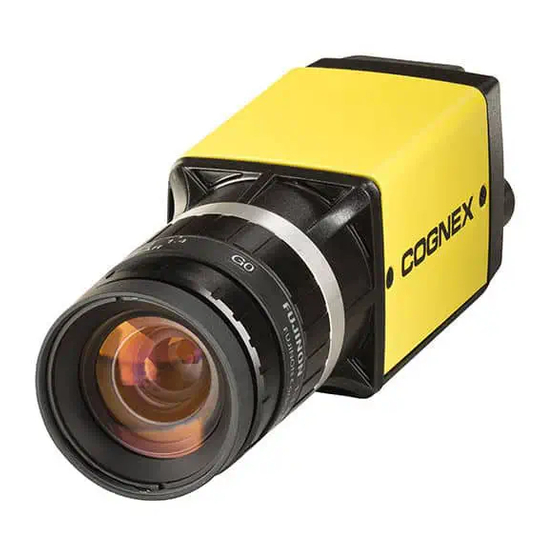
The In-Sight online support site: http://www.cognex.com/Support/InSight. Standard Components Note: Cables are sold separately. If any of the standard components appear to be missing or damaged, immediately contact your Cognex Authorized Service Provider (ASP) or Cognex Technical Support. Component Description Vision System Provides image acquisition, vision processing, job storage, Ethernet connectivity and discrete I/O. -
Page 10: Accessories
Introduction Accessories The following components can be purchased separately. For a complete list of options and accessories, contact your local Cognex sales representative. Cables Note: Cables are sold separately. CAUTION: All cable connectors are “keyed” to fit the connectors on the vision system; do not force the connections or damage may occur. - Page 11 Ethernet Cable (In-Sight 8200 and 8400 Series) The Ethernet cable provides Ethernet connectivity and supplies power to the vision system. The pin-outs for the cable are listed in the Ethernet Cable Specifications (In-Sight 8200 and 8400 Series) on page 32. Length...
-
Page 12: Mounting Block Kit
Introduction Mounting Block Kit The mounting block kit includes M3 screws for mounting the vision system (quantity 4) and a mounting block for securing the vision system to a mounting surface. Description Part Number Mounting kit and M3 screws BKT-IS8K-01 CIO-MICRO I/O Module The CIO-MICRO I/O module provides access to power, serial, trigger, high-speed outputs and additional discrete inputs and discrete outputs. -
Page 13: Connectors And Indicators
The ENET port is a 10/100/1000 port that provides Gigabit Ethernet connectivity and supplies Ethernet Power over Ethernet (PoE) via the Ethernet cable. For more information, refer to Cable Specifications (In-Sight 8200 and 8400 Series) on page 32 Ethernet Cable Specifications (In-Sight 8405) on page 33... -
Page 14: Installation
Installation Installation This section describes the connection of the vision system to its standard components and accessories. For a complete list of options and accessories, contact your Cognex sales representative. Note: Cables are sold separately. CAUTION: All cable connectors are “keyed” to fit the connectors on the vision system; do not force the connections or damage may occur. -
Page 15: Install The Lens
Installation Install the Lens 1. Remove the protective film covering the threaded lens opening, if present. 2. Attach a C-Mount lens to the vision system. The exact lens focal length needed depends on the working distance and the field of view required for your machine vision application. -
Page 16: Connect The Inputs And Outputs (Optional)
Installation Connect the Inputs and Outputs (Optional) The vision system’s I/O connector supplies connections for the acquisition trigger and high-speed outputs. ® Note: The vision system must be Online for the discrete inputs and outputs to function. Refer to the In-Sight Explorer Help file for details on configuring the discrete input and output lines. -
Page 17: Option 2: Connect The I/O Module Cable
Installation Option 2: Connect the I/O Module Cable CAUTION: A ferrite is included with the In-Sight 8405 vision system standard components. To reduce emissions, the ferrite must be attached to the I/O Module cable. Note: The CIO-MICRO I/O module supports In-Sight 8000 series vision systems with firmware version 5.3.0 and higher. -
Page 18: Connect The Ethernet And Power
Installation Connect the Ethernet and Power The vision system’s PoE connector provides the Ethernet connection for network communications and supplies power to the vision system. The following steps illustrate how to connect the vision system to the In-Sight CIO-MICRO I/O module. If the CIO-MICRO I/O module is not used, a third-party PoE injector or a PoE switch must be used to supply power to the vision system. -
Page 19: Connect The Frame Ground Wire
Installation Connect the Frame Ground Wire Connect a frame ground wire to the I/O module’s Frame Ground terminal. Connect the other end of the frame ground wire to frame ground. CAUTION: The shield ground connections of the RS-232 port, LAN port, PoE port, I/O port and Frame Ground terminal are internally connected. -
Page 20: Connect An Rj-45 Lan Cable
Connect the Ethernet Cable CAUTION: The Ethernet cable must be shielded. For the In-Sight 8405 vision system, Cognex strongly recommends Cat 6 or Cat 7 Ethernet cables with S/STP shielding. The Ethernet cable shield must be grounded at the far end. If using a PoE injector, a ground wire should be connected from the Ethernet shield at the PoE injector to frame ground or Earth ground, and a digital voltmeter used to validate the grounding. - Page 21 Installation If installing the In-Sight 8405 vision system and using a compatible horizontal screw-locking Ethernet cable, use a screw driver to tighten the connector screws until snug, to secure it to the vision system. The screws must be tight to ensure a reliable connection. 2.
-
Page 22: Specifications
Specifications Specifications The following sections list general specifications for the vision system. In-Sight 8200 and 8400 Series Vision System Specifications Specifications 8200 8200C 8400 8400C 8401 8401C 8402 8402C Minimum Firmware In-Sight In-Sight In-Sight In-Sight In-Sight In-Sight In-Sight In-Sight Requirement... - Page 23 Specifications Specifications 8200 8200C 8400 8400C 8401 8401C 8402 8402C Voltage 48VDC nominal, applied from a Class 2 PoE device, which is typically powered from some other voltage. Material Die-cast zinc housing. Finish Painted. Mounting Four M3 threaded mounting holes (1/4-20 and M6 mounting holes also available on accessory mounting block).
-
Page 24: In-Sight 8405 Vision System Specifications
Specifications In-Sight 8405 Vision System Specifications Specifications 8405 Minimum Firmware In-Sight version 5.1.1 Requirement Job/Program Memory 512MB non-volatile flash memory; unlimited storage via remote network device. Image Processing 512MB SDRAM Memory Sensor Type 1/2.5 inch CMOS, rolling shutter Sensor Properties 7.13mm diagonal, 2.2 x 2.2µm sq. - Page 25 Specifications Specifications 8405 78 g (2.75 oz.) without accessory mounting block. Weight 109 g (3.84 oz.) with accessory mounting block. Case Temperature 0°C to 50°C (32°F to 122°F) Storage Temperature -20°C to 80°C (-4°F to 176°F) Humidity < 80% non-condensing Protection IP30 with cables and lens attached.
-
Page 26: Acquisition Trigger Input
Specifications Acquisition Trigger Input The vision system features one acquisition trigger input, which is optically isolated. The acquisition trigger input can be configured to trigger from either an NPN (current sinking) or PNP (current sourcing) device. Specification Description ON: 20 to 28VDC (24VDC nominal) Voltage OFF: 0 to 3VDC (8VDC nominal threshold) ON: 1.9 to 3.0mA from 20 to 28V input. -
Page 27: High-Speed Outputs
Specifications High-Speed Outputs The vision system features two built-in, high-speed outputs, which are optically isolated. The high-speed outputs can be used as either NPN (current sinking) or PNP (current sourcing) lines. Specification Description Voltage 28VDC maximum through external load. Current 100mA maximum sink current. -
Page 28: High-Speed Output - Npn Configuration
Specifications High-Speed Output - NPN Configuration The Breakout cable can be used to connect to an NPN-compatible PLC input. Connect HS OUT 0 or HS OUT 1 directly to the PLC input. When enabled, the output pulls the PLC input down to less than 3VDC. For more information, refer to Breakout Cable Specifications on page 30. -
Page 29: High-Speed Output - Relay/Led Configuration
Specifications High-Speed Output - Relay/LED Configuration The Breakout cable can be used to connect the high-speed outputs to a relay, LED or similar load. Connect the negative side of the load to the output and the positive side to +24VDC. When the output switches on, the negative side of the load is pulled down to less than 3VDC, and greater than 21VDC appears across the load. -
Page 30: Breakout Cable Specifications
Specifications Breakout Cable Specifications The Breakout cable provides access to the vision system’s trigger and high-speed outputs. The Breakout cable can be connected to devices, such as a PLC, trigger sensor or strobe light. The Breakout cable is not terminated. P1 Pin Number Signal Name Wire Color... -
Page 31: I/O Module Cable Specifications
Specifications I/O Module Cable Specifications The I/O Module cable is used with the CIO-MICRO. The I/O Module cable connects the vision system directly to the I/O module via the DB15 connector. When connected, the I/O Module cable provides access to the vision system’s trigger and high-speed outputs. -
Page 32: Ethernet Cable Specifications (In-Sight 8200 And 8400 Series)
Specifications Ethernet Cable Specifications (In-Sight 8200 and 8400 Series) The Ethernet cable provides Ethernet connectivity and supplies power to the vision system. P1 Pin Number Wire Color Signal Name P2 Pin Number White/Orange TxRx A + Orange TxRx A -... - Page 33 Note: Cables are sold separately. CAUTION: The Ethernet cable must be shielded. For the In-Sight 8405 vision system, Cognex strongly recommends Cat 6 or Cat 7 Ethernet cables with S/STP shielding. The Ethernet cable shield must be grounded at the far end. If using a PoE injector, a ground wire should be connected from the Ethernet shield at the PoE injector to frame ground or Earth ground, and a digital voltmeter used to validate the grounding.
-
Page 34: In-Sight 8200 And 8400 Series Dimensions
Specifications In-Sight 8200 and 8400 Series Dimensions Note: All dimensions are in millimeters [inches] and are for reference purposes only. All specifications are for reference purpose only and may be changed without notice. -
Page 35: In-Sight 8200 And 8400 Series Dimensions (With Mounting Block)
Specifications In-Sight 8200 and 8400 Series Dimensions (with Mounting Block) Note: All dimensions are in millimeters [inches] and are for reference purposes only. All specifications are for reference purpose only and may be changed without notice. -
Page 36: In-Sight 8405 Dimensions
Specifications In-Sight 8405 Dimensions Note: All dimensions are in millimeters [inches] and are for reference purposes only. All specifications are for reference purpose only and may be changed without notice. -
Page 37: In-Sight 8405 Dimensions (With Mounting Block)
Specifications In-Sight 8405 Dimensions (with Mounting Block) Note: All dimensions are in millimeters [inches] and are for reference purposes only. All specifications are for reference purpose only and may be changed without notice. -
Page 38: Cleaning/Maintenance
Cleaning/Maintenance Cleaning/Maintenance Clean the Vision System Housing To clean the outside of the vision system housing, use a small amount of mild detergent cleaner or isopropyl alcohol on a cleaning cloth. Do not pour the cleaner directly onto the vision system housing. CAUTION: Do not attempt to clean any In-Sight product with harsh or corrosive solvents, including lye, methyl ethyl ketone (MEK) or gasoline.
Need help?
Do you have a question about the In-Sight 8200 and is the answer not in the manual?
Questions and answers