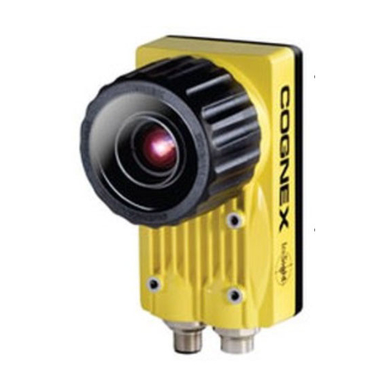
Cognex In-Sight 5100 Reference Manual

Cognex In-Sight 5100 Reference Manual

In-sight 5000 series
Hide thumbs Also See for In-Sight 5100:

Advertisement

In-Sight
Vision System
Reference Guide
2018 March 23
Revision: 5.6.0.15
®
5000 Series

Advertisement

Table of Contents
loading
Need help?

Need help?

Do you have a question about the In-Sight 5100 and is the answer not in the manual?

Questions and answers

Summary of Contents for Cognex In-Sight 5100

  • Page 1 ® In-Sight 5000 Series Vision System Reference Guide 2018 March 23 Revision: 5.6.0.15...
  • Page 2: Legal Notices

    Copyright © 2003 - 2016. Cognex Corporation. All Rights Reserved. Portions of the hardware and software provided by Cognex may be covered by one or more U.S. and foreign patents, as well as pending U.S. and foreign patents listed on the Cognex web site at: http://www.cognex.com/patents.
  • Page 3: Regulations/Conformity

    Regulations/Conformity Regulations/Conformity Note: For the most up-to-date CE declaration and regulatory conformity information, please refer to the Cognex online support site: http://www.cognex.com/Support. Safety and Regulatory Cognex Corporation Manufacturer One Vision Drive Natick, MA 01760 USA In-Sight 5100/5110/5400/5410: Type 821-0034-1R In-Sight 5100C/5400C: Type 821-0036-1R...
  • Page 4 Regulations/Conformity Safety and Regulatory Cognex Corporation Manufacturer One Vision Drive Natick, MA 01760 USA In-Sight 5600/5610: Type 821-0041-1R In-Sight 5603/5613: Type 821-0042-1R In-Sight 5604/5614: Type 821-0051-1R In-Sight 5605/5615: Type 821-0032-1R; Type 821-0032-2R In-Sight 5705/5715/5705C: Regulatory Model 1AAF FCC Part 15, Class A This device complies with Part 15 of the FCC Rules.
  • Page 5: For European Community Users

    Regulations/Conformity For European Community Users Cognex complies with Directive 2012/19/EU OF THE EUROPEAN PARLIAMENT AND OF THE COUNCIL of 4 July 2012 on waste electrical and electronic equipment (WEEE). This product has required the extraction and use of natural resources for its production. It may contain hazardous substances that could impact health and the environment, if not properly disposed.
  • Page 6: Precautions

    Precautions Precautions Observe these precautions when installing the Cognex product, to reduce the risk of injury or equipment damage: In-Sight 5000 series vision systems are intended to be supplied by a UL or NRTL listed power supply with a 24VDC output rated for at least 600 mA continuous and a maximum short circuit current rating of less than 8A and a maximum power rating of less than 100VA and marked Class 2 or Limited Power Source (LPS).
  • Page 7: Table Of Contents

    Table of Contents Table of Contents Legal Notices Regulations/Conformity For European Community Users Precautions Table of Contents Introduction Support Standard Components Accessories Cables I/O Modules Installation Connectors and Indicators Install the Lens Connect the Ethernet Cable Connect the Breakout Cable Specifications 5100, 5100C, 5400C, 5403 and 5400 Vision System Specifications 5603, 5600 and 5605 Vision System Specifications...
  • Page 8: Introduction

    The In-Sight Explorer Help and EasyBuilder Help files, provided with In-Sight Explorer software. On-demand training: http://www.cognex.com/on-demand-training.aspx. The In-Sight online support site: http://www.cognex.com/Support/InSight. Standard Components The vision system is shipped with the standard components listed below. Note: Cables are sold separately.
  • Page 9: Accessories

    Introduction Accessories The following components can be purchased separately. For a complete list of options and accessories, contact your local Cognex sales representative. Cables Note: Cables are sold separately. CAUTION: All cable connectors are “keyed” to fit the connectors on the vision system; do not force the connections or damage may occur.
  • Page 10 Introduction Breakout Cable The Breakout cable provides connection to an external power supply, RS-232 serial communications, acquisition trigger input, high-speed outputs and encoder inputs (In-Sight 5604 only). The pin-outs for the cable are listed in the Breakout Cable Specifications on page 30.
  • Page 11: I/O Modules

    Introduction I/O Module Cable The I/O Module cable connects the vision system directly to a compatible In-Sight I/O module via the DB15 connector. The pin-outs for the cable are listed in the I/O Module Cable Specifications on page 31. This cable is available in the lengths listed below.
  • Page 12 Ethernet cable to the Gigabit Ethernet switch. The CIO-MICRO & CIO-MICRO-CC I/O modules support In-Sight 5100 series and 5400 series vision systems with 128MB non-volatile flash memory or higher and support all In-Sight 5600 series vision systems.
  • Page 13: Installation

    Cognex sales representative. Note: Cables are sold separately. If any of the standard components appear to be missing or damaged, immediately contact your Cognex Authorized Service Provider (ASP) or Cognex Technical Support. CAUTION: All cable connectors are “keyed”...
  • Page 14: Install The Lens

    Note: For the In-Sight 5100 and 5400 series, when the vision system is powered up, User 0 LED and User 1 LED both momentarily turn on. Then, User 0 LED turns off and User 1 LED stays on. Next, User 0 LED turns on and User 1 LED turns off.
  • Page 15: Connect The Breakout Cable

    Installation Connect the Breakout Cable Note: Unused wires can be clipped short or tied back using a tie made of non-conductive material. Keep all bare wires separated from the +24VDC wire. 1. Verify that the 24VDC power supply being used is unplugged and not receiving power. 2.
  • Page 16: Specifications

    IP address configuration. Communication The In-Sight firmware version 5.1.0 and higher is not supported on In-Sight 5100/5110, 5100C, 5400C, 5403/5413 and 5400/5410 vision systems. The number of image sensor rows are configurable and can be set within the In-Sight Explorer software. Decreasing the number of rows will ®...
  • Page 17 Specifications Specification 5100/5110 5100C 5400C 5403/5413 5400/5410 Timestamp Resolution: 8ns 1588 Support Synchronization Accuracy Through Transparent Clock: 5µs Serial RS-232C when connected to the Breakout Cable or a compatible I/O module. (For more information, I/O Modules on page 11 Communication refer to Power 24VDC ±10%, 500mA maximum.
  • Page 18: 5603, 5600 And 5605 Vision System Specifications

    Specifications 5603, 5600 and 5605 Vision System Specifications Specification 5603/5613 5600/5610 5605/5615 Minimum In-Sight version 4.4.3 In-Sight version 4.4.1 Firmware Requirement Job/Program 128MB non-volatile flash memory; unlimited storage via remote network device. Memory Image 256MB SDRAM Processing Memory Sensor Type 1/1.8-inch CCD 1/3-inch CCD 2/3-inch CCD...
  • Page 19 Specifications Specification 5603/5613 5600/5610 5605/5615 Mounting Eight M4 threaded mounting holes (four front and four back). 99.9mm (3.93in) x 124.2mm (4.89in) x 61.4mm 134.4mm (5.29in) x 124.1mm (4.88in) x Dimensions (2.42in) with lens cover installed. 61.4mm (2.42in) with lens cover installed. 60.1mm (2.37in) x 124.2m (4.89in) x 61.4mm (2.42in) 53.2mm (2.09in) x 124.1mm (4.88in) x without lens cover installed.
  • Page 20: 5604 Line Scan Vision System Specifications

    Specifications 5604 Line Scan Vision System Specifications Specification 5604/5614 Minimum Firmware In-Sight version 4.4.3 Requirement Job/Program 128MB non-volatile flash memory; unlimited storage via remote network device. Memory Image Processing 256MB SDRAM Memory Sensor Type 1-inch CCD Sensor Properties 14.3 mm x 14µm active area, 14µm x 14µm sq. pixels. Maximum 1024 x 1 (CCD);...
  • Page 21 Specifications Specification 5604/5614 Operating 0°C to 50°C (32°F to 122°F) Temperature (circulating air) Storage -30°C to 80°C (-22°F to 176°F) Temperature Humidity 95%, non-condensing (Operating and Storage) Protection IP67 (with appropriate lens cover properly installed). Shock (Shipping 80 G Shock with 150 gram lens attached per IEC 68-2-27. and Storage) Vibration (Shipping 10 G from 10-500 Hz with 150 gram lens per IEC 68-2-6.
  • Page 22: 5705 And 5705C Vision System Specifications

    Specifications 5705 and 5705C Vision System Specifications Specification 5705/5715 5705C Minimum Firmware In-Sight version 5.1.0 Requirement Job/Program Memory 128MB non-volatile flash memory; unlimited storage via remote network device. Image Processing Memory 512MB SDRAM Sensor Type 2/3-inch CCD Sensor Properties 11.01mm diagonal, 3.45 x 3.45µm sq. pixels Maximum Resolution (pixels) 2448 x 2048 Electronic Shutter Speed...
  • Page 23 Specifications Specification 5705/5715 5705C Operating Temperature 0°C to 50°C (32°F to 122°F) (circulating air) Storage Temperature -30°C to 80°C (-22°F to 176°F) Humidity 95%, non-condensing (Operating and Storage) Protection IP67 (with appropriate lens cover properly installed). Shock (Shipping and Storage) 80 G Shock with 150 gram lens attached per IEC 68-2-27. Vibration (Shipping and 10 G from 10-500 Hz with 150 gram lens per IEC 68-2-6.
  • Page 24: I/O Specifications

    ON: 2.0 to 2.9mA Current OFF: < 250µA Resistance: ~10 kOhms In-Sight 5100, 5110, 5100C, 5400C, 62µs maximum latency between leading edge of trigger and Delay 5400, 5410, 5600, 5610 start of acquisition. Input pulse should be a minimum of 1ms wide.
  • Page 25: Encoder Inputs (In-Sight 5604 Only)

    Specifications Note: When using the vision system with the Breakout cable, the polarity of the TRIGGER+ and TRIGGER- pins is not critical. However, when using an optional I/O module, the polarity of the TRIGGER+ and TRIGGER- pins should be observed. Encoder Inputs (In-Sight 5604 Only) The Breakout cable can be used for communication between the vision system and a single or quadrature encoder.
  • Page 26: High-Speed Outputs

    Specifications High-Speed Outputs In-Sight 5000 series vision systems feature two built-in, high-speed outputs. Both of the high-speed outputs are NPN (current sinking) lines. The external load should be connected between the output and the positive supply voltage (28VDC or less). The outputs pull down to 0.1VDC or less when ON (1.25VDC or less for In-Sight 5604 only), which causes current to flow through the load.
  • Page 27 Specifications High-Speed Output - PNP Configuration The Breakout cable can be used to connect high-speed outputs with a PNP-compatible PLC input, if a pull-up resistor (for example, 2.2 kOhms 0.5W) is connected from the output to +24VDC. In this case, the resistor supplies 24VDC to the PLC input.
  • Page 28: 5100 And 5400 Series Vision System Ethernet Cable Specifications

    Specifications 5100 and 5400 Series Vision System Ethernet Cable Specifications The Ethernet cable is used to connect the vision system to other network devices. The Ethernet cable can be connected to a single device or provide connections to multiple devices via a network switch or router. P1 Pin# Signal Name Wire Color...
  • Page 29: 5600 And 5700 Series Vision System Ethernet Cable Specifications

    To ensure reliable communication using 1000 BaseT operation, the Ethernet cable must not exceed 75 meters (from the vision system to the endpoint). Cognex cables or patch cables should not exceed 5 meters and HCC (plenum wiring) should not exceed 60 meters. It's not recommended to use a 30 meter cable when using 1000 BaseT operation.
  • Page 30: Breakout Cable Specifications

    Specifications Breakout Cable Specifications The Breakout cable provides connection to an external power supply, RS-232 serial communications, acquisition trigger input, high-speed outputs and encoder inputs (In-Sight 5604 only). The Breakout cable is not terminated. When using the In-Sight 5604, refer to Encoder Inputs (In-Sight 5604 Only) on page 25.
  • Page 31: I/O Module Cable Specifications

    Specifications I/O Module Cable Specifications The I/O Module cable connects the vision system directly to a compatible In-Sight I/O module via the DB15 connector. When the I/O module is used, all power and communication lines used by the vision system are connected using the I/O Module cable.
  • Page 32: Dimensional Drawings

    Specifications Dimensional Drawings 5100, 5100C, 5400, 5400C and 5403 Vision System (With Lens Cover) Note: All dimensions are in millimeters [inches] and are for reference purposes only. All specifications are for reference purpose only and may be changed without notice.
  • Page 33: 5100, 5100C, 5400, 5400C And 5403 Vision System (Without Lens Cover)

    Specifications 5100, 5100C, 5400, 5400C and 5403 Vision System (Without Lens Cover) Note: All dimensions are in millimeters [inches] and are for reference purposes only. All specifications are for reference purpose only and may be changed without notice.
  • Page 34: 5600 And 5603 Vision System (With Lens Cover)

    Specifications 5600 and 5603 Vision System (With Lens Cover) Note: All dimensions are in millimeters [inches] and are for reference purposes only. All specifications are for reference purpose only and may be changed without notice.
  • Page 35: 5600 And 5603 Vision System (Without Lens Cover)

    Specifications 5600 and 5603 Vision System (Without Lens Cover) Note: All dimensions are in millimeters [inches] and are for reference purposes only. All specifications are for reference purpose only and may be changed without notice.
  • Page 36: 5604, 5605, 5705, And 5705C Vision System (With Lens Cover)

    Specifications 5604, 5605, 5705, and 5705C Vision System (With Lens Cover) Note: All dimensions are in millimeters [inches] and are for reference purposes only. All specifications are for reference purpose only and may be changed without notice.
  • Page 37: 5604, 5605, 5705, And 5705C Vision System (Without Lens Cover)

    Specifications 5604, 5605, 5705, and 5705C Vision System (Without Lens Cover) Note: All dimensions are in millimeters [inches] and are for reference purposes only. All specifications are for reference purpose only and may be changed without notice.
  • Page 38: Cleaning/Maintenance

    Cleaning/Maintenance Cleaning/Maintenance Clean the Vision System Housing To clean the outside of the vision system housing, use a small amount of mild detergent cleaner or isopropyl alcohol on a cleaning cloth. Do not pour the cleaner directly onto the vision system housing. CAUTION: Do not attempt to clean any In-Sight product with harsh or corrosive solvents, including lye, methyl ethyl ketone (MEK) or gasoline.

Table of Contents

Save PDF