Summarization of Contents
Chapter 1: Introduction
Purpose
Provides conceptual information and installation procedures for Avaya VSP 7000 Series hardware.
Related Resources
Lists related documentation, training, and support resources for the VSP 7000 Series.
Documentation
Details how to find the Documentation Roadmap Reference for Avaya VSP 7000 Series.
Training
Provides information on ongoing product training and registration for Avaya VSP 7000 Series.
Avaya Mentor Videos
Explains how to access Avaya Mentor videos for technical content on VSP 7000 Series products.
Support
Guides users to the Avaya Support website for documentation, notices, and service requests.
Searching Documentation
Details how to perform an index search of the documentation collection on the Avaya website.
Chapter 7: Preparations for Network Connectivity
Console and Management Connections
Describes the front panel console and management ports on the VSP 7000 Series switch.
Out-of-Band Management Port
Explains the use of the Out-of-Band Management port for diagnostics and remote management.
USB Port
Details the USB 2.0 port functionality for connecting flash drives on the VSP 7000 Series.
VSP 7024XT 10GBase-T Status
Explains the LEDs for connection speed and link activity on VSP 7024XT 10GBase-T ports.
Small-Form-Factor Transceivers
Lists supported SFP and SFP+ transceivers for Gigabit and 10 Gigabit connections.
Validated Third-Party Devices
Lists third-party SFP+ devices validated by Avaya for compatibility with VSP 7000.
SFP Port LEDs
Describes the status LEDs (Tx/Rx) on the front panel for SFP ports.
Installing SFP Transceivers
Provides procedures for installing SFP or SFP+ transceivers and network cabling.
Quad-Small-Form-Factor-Pluggable Transceivers
Details Avaya QSFP+ transceivers for 40 Gbps connections and QSFP+ support.
Media Dependent Adapter (MDA)
Describes the MDA as an expansion module to increase VSP 7000 Series port capacity.
MDA Warm and Hot Swap
Explains methods for installing, removing, and swapping Media Dependent Adapters.
Installing an MDA
Provides steps to insert a Media Dependent Adapter into the MDA slot on the switch.
Chapter 2: New in this Release
Features
Highlights new features introduced in VSP 7000 Release 10.3, 10.3.1, and 10.3.2.
7002QQ MDA
Introduces the 7002QQ MDA with two 40GBase QSFP+ ports for VSP 7000 Series switches.
QSFP+ Transceivers
Details Avaya QSFP+ transceivers for 40 Gbps speeds and supported types.
VSP 7024XT Switch
Introduces the VSP 7024XT switch with 24 x 10GBase-T ports and one MDA.
MDA Hot Swap
Explains the support for hot swapping Media Dependent Adapters in VSP 7000 Series Release 10.3.
SFP+ Devices
Details new support for SFP+ 10GBASE-ZR/ZW and CWDM devices.
Chapter 3: Safety Messages
General Safety Warnings
Essential safety guidelines for installation and operation, including voltage and fiber optic hazards.
Chapter 4: Installation Preparation
VSP 7000 Series Switch Models
Describes the VSP 7024XLS and VSP 7024XT switch models and their features.
Environmental Requirements
Outlines acceptable operating ranges for temperature, humidity, altitude, and acoustic noise.
Verifying Environmental Suitability
Provides a procedure to check if the physical location meets environmental requirements.
Cooling Fans and Power Supplies
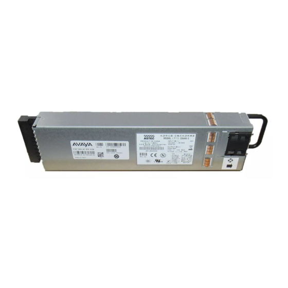
Details fan trays and field-replaceable power supplies for VSP 7000 Series switches.
Redundant Power Supply Configurations
Explains redundancy, load sharing, and hot-swap capabilities for dual power supplies.
Power Supply Monitoring
Describes how power supplies send information to the switch software for monitoring.
Installing Fan Trays and Power Supply
Provides steps for installing fan trays and power supplies into the VSP 7000 Series switch.
Power Specifications
Lists supported power supply configurations and airflow patterns for VSP 7000 Series switches.
Power Connections
Describes how to connect AC and DC power sources to the VSP 7000 Series switch.
AC Power Connections
Details AC power cord specifications and connection procedures for the VSP 7000 Series.
International Power Cord Specs
Provides specifications for power cords in Continental Europe, US/Canada/Japan, UK, and Australia.
Connecting AC Power
Outlines the procedure to connect an AC power source to the VSP 7000 Series switch.
DC Power Connections
Details DC power cable requirements and connection procedures for the VSP 7000 Series.
DC Power Supply Connections
Explains how to connect DC power cables to the VSP 7000 Series power supply.
Connecting DC Power
Provides steps to connect a DC power source to the VSP 7000 Series switch.
Chapter 5: Switch Installation
Switch Placement Options
Describes options for installing the VSP 7000 Series switch in racks or on flat surfaces.
Environmental Requirements
Lists the environmental requirements for installing and operating the VSP 7000 Series switch.
Installing the Switch in an Equipment Rack
Provides a procedure to install the VSP 7000 Series switch into an equipment rack.
Installing Optional Four-Post Mount Brackets
Details the assembly and installation of the optional four-post rack-mount bracket kit.
Checking Status LEDs
Explains how to verify hardware installation and operation using status LEDs on the VSP 7000 Series.
Chapter 6: Fabric Interconnect Connectivity
Fabric Interconnect
Introduces Fabric Interconnect (FI) ports for VSP 7000 Series stackable and raw-mode deployments.
Fabric Interconnect Ports
Details the four FI ports on the VSP 7000 Series back panel and their bandwidth.
Base Unit
Explains how to designate a switch as the Base unit in a VSP 7000 Series stack.
Temporary Base Unit
Describes the role of a Temporary Base Unit (TBU) in case of Base unit failure in a stack.
Stack-mode DToR Configurations
Details how to connect VSP 7000 Series units for Stack-mode Distributed Top-of-Rack (DToR) deployments.
Fl-down Configuration
Explains the Fl-down cabling configuration where the Base unit is at the top of the stack.
Fl-up Configuration
Explains the Fl-up cabling configuration where the Base unit is at the top of the stack.
Redundant Stack-mode Configuration
Describes how to create a redundant FI cable loop for uninterrupted operation.
Rear Port Mode
Fabric-mode DToR Configurations
Details using rear port mode for Fabric-mode DToR deployments with topology-aware configurations.
Appendix A: Hardware Reliability
Mean Time Between Failures (MTBF)
Provides MTBF values for VSP 7000 Series hardware components.


Need help?
Do you have a question about the VSP 7024XT and is the answer not in the manual?
Questions and answers