Avaya 8000 Series Installing Manual
Virtual services platform
Hide thumbs
Also See for 8000 Series:
- Technical configuration manual (165 pages) ,
- Quick reference manual (6 pages)

Related Manuals for Avaya 8000 Series


Summary of Contents for Avaya 8000 Series
- Page 1 Installing the Avaya Virtual Services Platform 8000 Series Release 5.1 NN47227-300 Issue 07.04 November 2016...
- Page 2 CHANNEL PARTNER (AS APPLICABLE) UNDER A COMMERCIAL AGREEMENT WITH AVAYA OR AN AVAYA CHANNEL PARTNER. Avaya is not responsible for the contents or reliability of any linked UNLESS OTHERWISE AGREED TO BY AVAYA IN WRITING, websites referenced within this site or documentation provided by AVAYA DOES NOT EXTEND THIS LICENSE IF THE SOFTWARE Avaya.
- Page 3 OR SHALL BE IMPLIED FOR ANY OTHER USE. ADDITIONAL written consent of Avaya can be a criminal, as well as a civil offense INFORMATION FOR H.264 (AVC) AND H.265 (HEVC) CODECS under the applicable law.
- Page 4 Marks without prior written consent from Avaya or such third party which may own the Mark. Nothing contained in this site, the Documentation, Hosted Service(s) and product(s) should be construed as granting, by implication, estoppel, or otherwise, any license or right in and to the Marks without the express written permission of Avaya or the applicable third party.
-
Page 5: Table Of Contents
Searching a documentation collection Chapter 2: New in this document.................. 12 Chapter 3: Hardware models for VSP 8000 Series.............. 13 Chapter 4: Preinstallation checklist.................. 18 Chapter 5: Installing the Avaya Virtual Services Platform 8000 Series...... 20 ....................... 20 Installation checklist ....................... 21 Installation fundamentals ...................... - Page 6 RJ45 port LED state indicators .................. 86 Channelized LED state indicators ...... 86 Enterprise Device Manager (EDM) representation of physical LED status ...................... 87 40GBASE-QSFP+ ports Chapter 6: Translations of safety messages................ 88 November 2016 Installing the Avaya VSP 8000 Series Comments on this document? infodev@avaya.com...
-
Page 7: Chapter 1: Introduction
This guide provides information and instructions to install Avaya Virtual Services Platform 8000 Series switches. This document is renamed to Installing the Avaya Virtual Services Platform 8000 Series, NN47227-300. Avaya Virtual Services Platform 8000 Series includes Avaya Virtual Services Platform 8200 and Avaya Virtual Services Platform 8400. -
Page 8: Subscribing To E-Notifications
Avaya Mentor videos provide technical content on how to install, configure, and troubleshoot Avaya products. About this task Videos are available on the Avaya Support website, listed under the video document type, and on the Avaya-run channel on YouTube. Procedure •... - Page 9 8. Scroll through the list, and then select the product name. 9. Select a release version. 10. Select the check box next to the required documentation types. November 2016 Installing the Avaya VSP 8000 Series Comments on this document? infodev@avaya.com...
-
Page 10: Support
Searching a documentation collection On the Avaya Support website, you can download the documentation library for a specific product and software release to perform searches across an entire document collection. For example, you can perform a single, simultaneous search across the collection to quickly find all occurrences of a particular feature. - Page 11 The search results show the number of documents and instances found. You can sort the search results by Relevance Ranking, Date Modified, Filename, or Location. The default is Relevance Ranking. November 2016 Installing the Avaya VSP 8000 Series Comments on this document? infodev@avaya.com...
-
Page 12: Chapter 2: New In This Document
Chapter 2: New in this document There are no changes for VOSS 5.1 in Installing the Avaya Virtual Services Platform 8000 Series, NN47227-300. November 2016 Installing the Avaya VSP 8000 Series Comments on this document? infodev@avaya.com... -
Page 13: Chapter 3: Hardware Models For Vsp 8000 Series
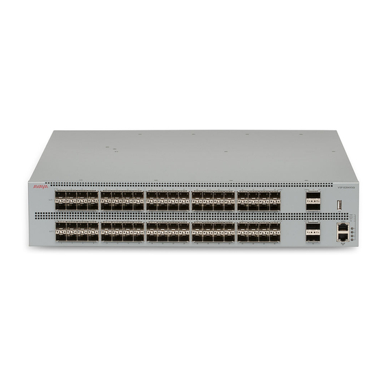
Chapter 3: Hardware models for VSP 8000 Series This section lists the VSP 8000 Series hardware. VSP 8200 hardware Table 1: VSP 8284XSQ Hardware VSP 8284XSQ Description Part number VSP 8284XSQ-AC • 80 ports of 10GBASE-SFP+ EC8200x01-E6 This model number ships with •... - Page 14 The universal slide rack mount kit is optional and must be ordered separately. VSP 7200, VSP 8200 and VSP 8400 ship with rack mount brackets. When using rack mount brackets on VSP 8200 and VSP 8400, Avaya recommends the use of a shelf to provide additional support. VSP 8400 hardware The following tables describe the VSP 8404 hardware.
- Page 15 *Note: The character (x) in the order number indicates the power cord code. Replace the “x” with the proper letter to indicate desired product nationalization. See the following for details: “A”: No power cord included. Table continues… November 2016 Installing the Avaya VSP 8000 Series Comments on this document? infodev@avaya.com...
- Page 16 The universal slide rack mount kit is optional and must be ordered separately. VSP 7200, VSP 8200 and VSP 8400 ship with rack mount brackets. When using rack mount brackets on VSP 8200 and VSP 8400, Avaya recommends the use of a shelf to provide additional support. Table 3: VSP 8400 Ethernet switch modules (ESMs)
-
Page 17: Compatible Transceivers
Avaya will not be responsible for issues related to non-Avaya branded transceivers. • The VSP 8000 Series operates in forgiving mode for SFP transceivers, which means that the switch will bring up the port operationally when using non-Avaya SFP transceivers. -
Page 18: Chapter 4: Preinstallation Checklist
Chapter 4: Preinstallation checklist Before you install the Avaya Virtual Services Platform 8000 Series, make sure that you complete the tasks in the preinstallation checklist. Task Description Review the technical specification for For the physical, electrical, and environmental the switch. Make sure that the area... - Page 19 Task Description permanent and must not exceed 1 Ohm of resistance from the rack to the grounding electrode. November 2016 Installing the Avaya VSP 8000 Series Comments on this document? infodev@avaya.com...
-
Page 20: Chapter 5: Installing The Avaya Virtual Services Platform 8000 Series
Chapter 5: Installing the Avaya Virtual Services Platform 8000 Series This section provides the information and procedures to install the Avaya Virtual Services Platform 8000 Series. Installation checklist Use this checklist to install the Avaya Virtual Services Platform 8000 Series. -
Page 21: Installation Fundamentals
SFP, SFP+, and QSFP+ port LED state indicators on page 84. 2. Eighty SFP+ ports that support Avaya’s 1G SFPs and 10G SFP+s. • 40 ports in Slot 1 on top • 40 ports in Slot 2 on the bottom 3. - Page 22 Installing the Avaya Virtual Services Platform 8000 Series 7. Management port — The LEDs are on the bottom of the port. For more information, see Management port LEDs on page 83. 8. LEDs for system power (PWR), switch status (Status), redundant power supply (RPS), and fan modules (Fan).
- Page 23 8424GT (GSA Version) - EC8404008-E6GS 2. LEDs for system power (PWR), switch status (Status), redundant power supply (RPS), and fan modules (Fan). 3. USB port 4. Console port November 2016 Installing the Avaya VSP 8000 Series Comments on this document? infodev@avaya.com...
-
Page 24: Ethernet Switch Module
Installing the Avaya Virtual Services Platform 8000 Series 5. OOB management port Ethernet Switch Module An Ethernet Switch Module (ESM) is a field replaceable expansion module that provides physical interfaces on the VSP 8400. The VSP 8400 provides four expansion slots. - Page 25 • 8418XTQ (GSA version) — EC8404006-E6GS – 16 1/10G Copper and 2 40G-QSFP+ ports. Dimension 4.4cm – 1RU (H), 20.32cm (W), 29.21cm (D) Weight 4.0 lbs = 1.81 kg Power and 136W (max) = 464 BTU/hr thermal November 2016 Installing the Avaya VSP 8000 Series Comments on this document? infodev@avaya.com...
-
Page 26: Installing An Ethernet Switch Module
Installing the Avaya Virtual Services Platform 8000 Series Figure 8: 8418XTQ 8424GS • 8424GS — EC8404007-E6 – 24 100/1000M-SFP ports. • 8424GS (GSA version) — EC8404007-E6GS – 24 100/1000M-SFP ports. Dimension 4.4cm – 1RU (H), 20.32cm (W), 29.21cm (D) Weight 2.75 lbs = 1.25 kg... - Page 27 • Do not over tighten screws. Tighten until snug. Do not use a power tool to tighten screws. Procedure 1. Remove the two screws that secure the module bay cover to the chassis. (Save the module bay cover for possible future use.) November 2016 Installing the Avaya VSP 8000 Series Comments on this document? infodev@avaya.com...
- Page 28 Installing the Avaya Virtual Services Platform 8000 Series 2. Slide the module into the bay. 3. Apply gentle pressure anywhere on the faceplate to fully insert the module, and then screw the module in to ensure a good connection and to secure it to the chassis.
-
Page 29: Hot Swap Of Vsp 8400 Ethernet Switch Module
The VSP 8400 supports the hot swap of ESMs, power supply units and fan modules. The following table explains the method of hot swapping in VSP 8400. November 2016 Installing the Avaya VSP 8000 Series Comments on this document? infodev@avaya.com... -
Page 30: 40G Channelization
Installing the Avaya Virtual Services Platform 8000 Series Table 4: Methods of hot swapping in VSP 8400 Hardware Description Power supply You can hot swap power supplies while the switch is operational. One power supply is required for continuous switch operation. -
Page 31: Preventing Electrostatic Discharge Damage
• Do not remove the wrist or ankle strap until the installation is complete. Preventing electrostatic damage in new cable installations With new cable installations, Avaya recommends that you use an ESD discharge cable to reduce the potential for damage from static, that can build up in cables. The following figure illustrates an ESD cable. -
Page 32: Technical Specifications
Installing the Avaya Virtual Services Platform 8000 Series Figure 11: Job aid To install the ESD discharge cable, perform this procedure. 1. Connect the ground lug on the ESD discharge cable to a safe and suitable earth ground. 2. Connect all RJ-45 cable connectors to the female RJ-45 connector of the ESD discharge cable for at least 5 seconds, and then connect each RJ-45 cable connector to the switch. - Page 33 0 to 95 percent noncondensing Maximum Operating Altitude 3,048m (10 000 feet) above sea level Storage Altitude 0 to 12,192m (0 to 40,000 feet) above sea level Table continues… November 2016 Installing the Avaya VSP 8000 Series Comments on this document? infodev@avaya.com...
-
Page 34: Package Contents
• Screws to attach brackets to the switch • Screws to secure the switch to the equipment rack 3. The Avaya Virtual Services Platform 8000 Series supports two field-replaceable power supplies. One power supply ships with the unit. 4. Power cord 8200 •... -
Page 35: Installing The Vsp 8000 Series In An Equipment Rack
Series. The illustrations show the VSP 8200 as an example, but the instructions apply to any switch in the series. There are different ways to install an Avaya Virtual Services Platform 8000 Series switch in an equipment rack. Refer to one of the following sections: •... -
Page 36: Using The Optional Slide Rack Mount Kit
Installing the Avaya Virtual Services Platform 8000 Series • The rack is grounded to the same grounding electrode used by the power service in the area. The ground path must be permanent and must not exceed 1 Ohm of resistance from the rack to the grounding electrode. - Page 37 Installing the VSP 8000 Series in an equipment rack Figure 12: Shipping components Rails The following figure shows a slide rail in the default configuration for a 300mm-600mm equipment rack. This configuration comes with the short rear bracket installed. The slide rail actually consists of two separate rails that slide into each other: •...
- Page 38 Installing the Avaya Virtual Services Platform 8000 Series Figure 13: Rails Brackets There are three different brackets: • Short rear bracket—The slide rail kit comes with this bracket installed for the 300mm-600mm default configuration. Figure 14: Short rear bracket November 2016 Installing the Avaya VSP 8000 Series Comments on this document? infodev@avaya.com...
- Page 39 Installing the VSP 8000 Series in an equipment rack • Extension bracket—This bracket connects to the rack rail to lengthen it for a 600mm-900mm configuration. • Long rear bracket—This bracket replaces the short rear bracket to modify the slide rail for a 600mm-900mm configuration.
- Page 40 Installing the Avaya Virtual Services Platform 8000 Series Figure 16: Thumbscrew lock and release latches • Thumbscrew lock—This feature is on the front end of the chassis rails, and is used to lock the switch in the home position of the equipment rack.
- Page 41 Installing the VSP 8000 Series in an equipment rack • White release latch—This latch is the white, plastic tab on the chassis rails. - When you first install the slide rails, use these latches to disconnect the chassis rail from the rack rail so you can install the chassis rail on the switch.
- Page 42 Installing the Avaya Virtual Services Platform 8000 Series Figure 20: Blue locking mechanism - When you first install the slide rails and you fully extended the rail, you can lift the locking mechanism to release the rail so it can slide back into the main part of the unit.
- Page 43 Installing the VSP 8000 Series in an equipment rack • Pin block—The pin block supports equipment racks with different shaped holes. - For racks with square holes, the pin block fits right into the holes in the rack. - For racks with large round holes, the pin block retracts halfway when you insert the rail into the rack.
- Page 44 Installing the Avaya Virtual Services Platform 8000 Series Installing slides in a 300mm-600mm equipment rack Use the following procedure to install your switch in an equipment rack with a depth between 300mm and 600mm. Before you begin Important: The Slide Rack Mount Kit is fairly complex due to its versatile design. To make your installation...
- Page 45 Installing the VSP 8000 Series in an equipment rack b. Pull the inner chassis rail and slide it out as far as you can. November 2016 Installing the Avaya VSP 8000 Series Comments on this document? infodev@avaya.com...
- Page 46 Installing the Avaya Virtual Services Platform 8000 Series c. Slide the white release latch in the direction of the arrow stamped on the lock and pull the chassis rail out of the rack rail. 4. Lift the blue locking mechanism on the rack rail to slide the outer section back into the main section.
- Page 47 Installing the VSP 8000 Series in an equipment rack 5. Use the following steps to attach the chassis rail to the chassis: a. Orient the chassis rail with the thumbscrew lock towards the front and position the rail over the standoffs on the chassis.
- Page 48 Installing the Avaya Virtual Services Platform 8000 Series c. Make sure the safety tab locks into place. 6. Use the following steps to secure the rack rails to the frame: a. Orient the rack rail so that the end with the black retaining latch is facing front.
- Page 49 Installing the VSP 8000 Series in an equipment rack c. Push the end of the retaining latch out so it opens up. d. Insert the bracket pins into the desired holes in the frame. The pin block accommodates three different rack types. In the default position, the pin block fits into racks with square holes.
- Page 50 Installing the Avaya Virtual Services Platform 8000 Series e. Close the retaining latch so that it wraps around the frame and locks into place. f. Repeat the above steps on the rear bracket. g. Repeat these steps for the rack rail on the other side of the frame.
- Page 51 Installing the VSP 8000 Series in an equipment rack b. Pull the blue latches on the chassis rails towards the front and slide the switch into the frame. Note: After you install the switch in a rack, slide it out until the lock (shown above) engages.
- Page 52 Installing the Avaya Virtual Services Platform 8000 Series Installing slides in a 600mm-900mm equipment rack Use the following procedure to install your switch in an equipment rack with a depth between 600mm and 900mm. Before you begin Important: The Slide Rack Mount Kit is fairly complex due to its versatile design. To make your installation...
- Page 53 Installing the VSP 8000 Series in an equipment rack b. Pull the inner chassis rail and slide it out as far as you can. November 2016 Installing the Avaya VSP 8000 Series Comments on this document? infodev@avaya.com...
- Page 54 Installing the Avaya Virtual Services Platform 8000 Series c. Slide the white release latch in the direction of the arrow stamped on the lock and pull the chassis rail out of the rack rail. 4. Lift the blue locking mechanism on the rack rail to slide the outer section back into the main section.
- Page 55 Installing the VSP 8000 Series in an equipment rack 5. Use the following steps to attach the chassis rail to the chassis: a. Orient the chassis rail with the thumbscrew lock towards the front and position the rail over the standoffs on the chassis.
- Page 56 Installing the Avaya Virtual Services Platform 8000 Series c. Make sure the safety tab locks into place. 6. Remove the two screws and nuts securing the short rear bracket to the rack rail. This bracket is for 300mm-600mm equipment racks only and is not used in this installation. Save the bracket for possible future use.
- Page 57 Installing the VSP 8000 Series in an equipment rack 7. Identify the extension bracket and the long rear bracket. Use these brackets to extend the rack rail for 600mm-900mm racks. November 2016 Installing the Avaya VSP 8000 Series Comments on this document? infodev@avaya.com...
- Page 58 Installing the Avaya Virtual Services Platform 8000 Series 8. Use the countersink screws with the following steps to attach the extension bracket to the rack rail: a. Push the blue release lock up and slide the middle rail out as far as possible.
- Page 59 Installing the VSP 8000 Series in an equipment rack Note: Using the bag with ten M4 screws, attach the extension bracket to the rack rail by inserting the screws from the rack rail side and then into the extension bracket.
- Page 60 Installing the Avaya Virtual Services Platform 8000 Series d. Insert the long rear bracket into the extension bracket assembly. e. Install the first two screws on the end of the long rear bracket. f. Lift the blue locking mechanism and slowly slide the rail back into the main assembly.
- Page 61 Installing the VSP 8000 Series in an equipment rack screws one at a time. 9. Use the following steps to secure the rack rails to the frame: a. Orient the rack rail so that the end with the black retaining latch is in the front of the rack.
- Page 62 Installing the Avaya Virtual Services Platform 8000 Series c. Push the end of the retaining latch out so it opens up. d. Insert the bracket pins into the desired holes in the frame. The pin block accommodates three different rack types. In the default position, the pin block fits into racks with square holes.
- Page 63 Installing the VSP 8000 Series in an equipment rack e. Close the retaining latch so that it wraps around the frame and locks into place. f. Repeat the above steps on the rear bracket. 10. Repeat these steps for the rack rail on the other side of the frame.
- Page 64 Installing the Avaya Virtual Services Platform 8000 Series b. Pull the blue release latches on the chassis rails towards the front and slide the switch into the frame. Note: After you install the switch in a rack, slide it out until the lock (shown above) engages.
- Page 65 Installing the VSP 8000 Series in an equipment rack Important notice about rack safety One prerequisite to installing the switch in an equipment rack is to bolt the equipment rack to the floor. This section emphasizes the safety issue if you do not bolt the rack to the floor.
- Page 66 Installing the Avaya Virtual Services Platform 8000 Series Removing the switch from an equipment rack Follow these steps if you have to remove the switch from an equipment rack. Important: This procedure requires two people. Procedure 1. Disconnect the power cord from the switch.
- Page 67 Installing the VSP 8000 Series in an equipment rack 3. While the person standing in back of the chassis slides both of the white release locks (one on each side of the chassis) towards the front, the person standing in front of the chassis pulls the chassis out of the rack.
-
Page 68: Using The Supplied Brackets
Installing the Avaya Virtual Services Platform 8000 Series Using the supplied brackets This procedure describes how to install the switch using the supplied brackets on a two-post or four- post equipment rack. The brackets secure the chassis and prevent it from sliding around during vibration or when inserting or extracting transceivers. -
Page 69: Cable Requirements For The Vsp 8000 Series
5. Verify that the switch is securely fastened to the rack. 6. Connect power and network connections to the switch. Cable requirements for the VSP 8000 Series The following table describes the cables required for an Avaya Virtual Services Platform 8000 Series. Table 8: Switch cable requirements... -
Page 70: Installation And Removal Of Transceivers
Installation and removal of transceivers The following sections describe how to install and remove transceivers in the Avaya Virtual Services Platform 8000 Series switch. In this context, the term transceiver refers to Small Form Factor Pluggable (SFP), SFP+, and Quad 4-channel SFP (QSFP+). -
Page 71: Console Port Pin Assignments
Console port pin assignments The following section describes the console port pin assignments for the RJ-45 connectors in the Avaya Virtual Services Platform 8000 Series. The Console port and Management port both use RJ-45 connectors. Table 9: Console port pin assignments... - Page 72 Installing the Avaya Virtual Services Platform 8000 Series There are two power supply slots (PSU1 on top and PSU2 on the bottom). • If you only have one power supply, you can install it in either PSU1 or PSU2. • If you install a second power supply, neither one acts as a primary power supply. The two power supplies load share equally.
-
Page 73: Ac Power Supply Specifications
You can hot swap power supplies while the switch is operational. One power supply is required for continued switch operation. AC power supply specifications The Avaya Virtual Services Platform 8000 Series comes with an 800 W AC power supply and you can install a secondary power supply for redundancy. Important: You must have either a power supply or a power supply cover in each bay to ensure proper ventilation. -
Page 74: Ac Power Cord Specifications
The following table describes the regulatory AC power specifications for the Avaya Virtual Services Platform 8000 Series. Note that regulatory power specifications are based on the maximum rated capacity of the power supplies and are not based on typical power consumption, which is typically lower. -
Page 75: Dc Power Supply
DC power supply Installing a DC power supply Important: Avaya does not support installing a combination of AC-input and DC-input power supplies in the same chassis. The Avaya Virtual Services Platform 8000 Series supports two field-replaceable 800 W power supplies. One comes with the switch and you can install a second power supply to provide redundancy and load sharing. - Page 76 Disconnecting the DC power supply wiring assembly from the power supply is the only way to turn off DC power to the Avaya Virtual Services Platform 8000 Series. Allow at least 30 seconds for the Avaya Virtual Services Platform 8000 Series to fully power down before restoring power.
- Page 77 4. Once you install a power supply, use the following steps to connect the DC power supply wiring assembly: a. Avaya supplies a DC power supply wiring assembly to connect the DC power supply to the DC input power source.
-
Page 78: Dc Power Supply Specifications
You can hot swap power supplies while the switch is operational. One power supply is required for continued switch operation. DC power supply specifications The Avaya Virtual Services Platform 8000 Series comes with one 800 W DC power supply and you can install a secondary power supply for redundancy. Important: You must have either a power supply or a power supply cover in each bay to ensure proper ventilation. -
Page 79: Removing A Power Supply
The following table describes the regulatory DC power specifications for the Avaya Virtual Services Platform 8000 Series switch. Note that regulatory power specifications are based on the maximum rated capacity of the power supplies and are not based on typical power consumption, which is typically lower. -
Page 80: Airflow Direction
The airflow direction for Avaya Virtual Services Platform 8200 and Avaya Virtual Services Platform 8400 is front-to-back. Installing a fan module The Avaya Virtual Services Platform 8000 Series comes with four 12–V fan modules for switch cooling. Figure 24: Fan module There are four sensors inside the chassis that monitor the temperature. - Page 81 5. Verify that the fan module is fully seated in the chassis and secure it with two thumb screws. 6. Enter the following command to check the temperature sensors inside the switch. November 2016 Installing the Avaya VSP 8000 Series Comments on this document? infodev@avaya.com...
-
Page 82: Led State Definitions
PHY2 Temperature LED state definitions The figures and tables in the following sections describe the LEDs on the Avaya Virtual Services Platform 8000 Series switch. The tables describe LED operation for a switch that finishes the power- on self-test. Warning: Fiber optic equipment can emit laser or infrared light that can injure your eyes. -
Page 83: Management Port Led State Indicators
The port admin is disabled. Amber (blinking) The port is not in use. Green (steady) The port has no data activity. Green (blinking) The port has data activity. November 2016 Installing the Avaya VSP 8000 Series Comments on this document? infodev@avaya.com... -
Page 84: Sfp, Sfp+, And Qsfp+ Port Led State Indicators
Installing the Avaya Virtual Services Platform 8000 Series SFP, SFP+, and QSFP+ port LED state indicators This section describes the transceiver port LED state indicators by color and fluctuation cues. SFP, SFP+ port LED state indicators These ports use the LED on the left side of the port (Link/Act) to indicate whether or not the link is established and if a transceiver is present and active. -
Page 85: Rj45 Port Led State Indicators
The port is operating at 1Gbps. Link/Activity Green (solid) The port has link and there is no data activity. Green (blinking) The port has link and there is data activity. Table continues… November 2016 Installing the Avaya VSP 8000 Series Comments on this document? infodev@avaya.com... -
Page 86: Channelized Led State Indicators
Installing the Avaya Virtual Services Platform 8000 Series Label Color and Status Description Green (slow blinking) The port is administratively disabled. Channelized LED state indicators The following table describes the channelization LED state indications provided by the color. These ports use In Use Link/Act to indicate whether or not the link is established. -
Page 87: 40Gbase-Qsfp+ Ports
Also avoid the use of break out cables in non-channelized 40 Gigabit ports because this can result in mismatched link status between link partners, which can lead to network issues. November 2016 Installing the Avaya VSP 8000 Series Comments on this document? infodev@avaya.com... -
Page 88: Chapter 6: Translations Of Safety Messages
Se il dispositivo viene installato in un rack, non impilare le unità direttamente una sull'altra. Ogni unità deve essere fissata al rack con le staffe di montaggio appropriate. Le staffe di montaggio non sono state progettate per supportare più unità. November 2016 Installing the Avaya VSP 8000 Series Comments on this document? infodev@avaya.com... - Page 89 Se nello slot non vengono installati moduli, assicurarsi di mantenere la piastra di copertura metallica in sede sopra lo slot. La rimozione della piastra impedisce la ventilazione e il corretto raffreddamento dell'unità. November 2016 Installing the Avaya VSP 8000 Series Comments on this document? infodev@avaya.com...
- Page 90 Use only power cords that have a grounding path. Without a proper ground, a person who touches the switch is in danger of receiving an electrical shock. Lack of a grounding path to the switch can result in excessive emissions. November 2016 Installing the Avaya VSP 8000 Series Comments on this document? infodev@avaya.com...
- Page 91 Warning: The lithium battery is not field replaceable. It should be removed and replaced by authorized personnel only. Contact Avaya Technical Support for assistance if the battery requires replacement. November 2016 Installing the Avaya VSP 8000 Series...