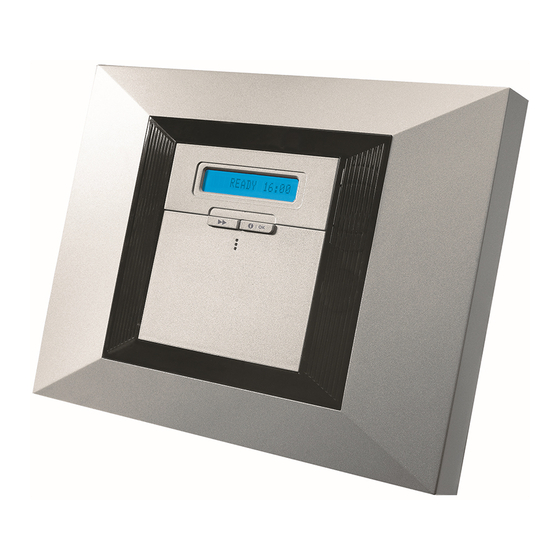
Visonic POWERMAX PRO Installer's Manual
Fully supervised wireless alarm control system
Hide thumbs
Also See for POWERMAX PRO:
- User manual (46 pages) ,
- Installer's manual (36 pages) ,
- Installation instructions (4 pages)
Table of Contents
Advertisement
Quick Links
Download this manual
See also:
User Manual
POWERMAX PRO
Fully Supervised Wireless Alarm Control System
TABLE OF CONTENTS
1. INTRODUCTION ....................................................... 3
2. SPECIFICATIONS..................................................... 3
2.1 General Data ...............................................................3
2.2 RF Section ...................................................................4
2.3 Electrical Data..............................................................4
2.4 Communication ............................................................4
2.5 Physical Properties ......................................................4
3. INSTALLATION ......................................................... 4
3.1 Unpacking the Equipment............................................4
3.2 Supplying Power to the Unit.........................................4
3.3 System Planning & Programming ................................4
3.4 Mounting ......................................................................4
3.5 Back Unit Mounting and Wiring ...................................4
3.5.1 Phone Wiring ............................................................5
3.5.2 Zones and Sirens Wiring ..........................................6
3.5.3 Installing an Optional X-10 Siren ..............................6
3.5.4 Dual RS-232 Module Mounting.................................7
3.5.5 Audio Module Mounting ............................................7
3.5.6 Power Cable Connection ..........................................7
3.6 Front Unit Preparation .................................................8
3.6.1 Backup Battery Insertion...........................................8
3.6.2 X-10 Interface Module Connection................................8
3.6.3 Optional GSM/GPRS Module Mounting....................8
3.7 Final Closure................................................................9
4. PROGRAMMING..................................................... 10
4.1 INTRODUCTION .......................................................10
4.1.1 General Guidance...................................................10
4.1.2 Entering an Invalid Installer Code................................10
4.1.3 Installer's Menu.......................................................10
4.1.4 Setting a New Installer Code ..................................10
has 2 Installer Codes .......................................................10
TRANSMITTERS.............................................................11
4.2.1 General Guidance...................................................11
4.2.2 Enrolling Type .........................................................11
4.2.3 Enroll/Delete Sensors................................................11
4.2.4 Enroll/Delete Keyfob Transmitters.................................11
4.2.5 Enroll/Delete Wireless Commander...............................11
4.2.6 Enroll/Delete 2-Way Keypad....................................11
4.2.7 Enroll/Delete Wireless Siren ....................................11
4.2.8 Enroll/Delete Proximity Tags....................................11
& PARTITION .............................................................. 13
4.4.1 Preliminary Guidance..............................................14
4.4.3 Exit Delay................................................................14
4.4.4 Bell Time.................................................................14
4.4.5 Abort Time ..............................................................14
4.4.6 Alarm Cancel ..........................................................15
4.4.7 Quick Arm ...............................................................15
4.4.8 Bypass ....................................................................15
4.4.9 Exit Mode................................................................15
4.4.10 Piezo Beeps..........................................................15
4.4.11 Trouble Beeps ......................................................15
4.4.12 Panic Alarm ..........................................................15
4.4.13 Swinger Stop ........................................................15
4.4.14 Cross Zoning ........................................................15
4.4.15 Supervision ...........................................................15
4.4.16 NOT READY.........................................................15
4.4.17 AUX Button A........................................................15
4.4.18 AUX Button B 2-W-KF.............................................16
4.4.19 Jam Detect............................................................16
4.4.20 Latchkey ...............................................................16
D-302541
4.4.21 "Not Active" .......................................................... 16
4.4.22 Back Light ............................................................ 16
4.4.23 Duress.................................................................. 16
4.4.24 Piezo Siren........................................................... 16
4.4.25 Reset Option ........................................................ 16
4.4.26 Tamper Option ..................................................... 16
4.4.27 Siren On Line ....................................................... 16
4.4.28 Memory Prompt.................................................... 16
4.4.29 Disarm Option......................................................... 16
4.4.30 Bell/Rep. Option ................................................... 16
4.4.31 Low-Bat Ack ......................................................... 16
4.4.32 Screen Saver ....................................................... 17
4.4.33 Confirm Alarm ...................................................... 17
4.4.34 AC FAIL REP ....................................................... 17
4.4.36 User Permission ................................................... 17
4.4.39 Key Zones Options (Optional) .............................. 17
Preliminary Guidance ...................................................... 19
4.5.1 PSTN / GSM (Fig. 4.5) ............................................ 19
4.5.2 GPRS / BB (Fig. 4.5).............................................. 19
4.5.3 C.S. Reporting (Fig. 4.5) ........................................ 20
4.5.4 Private Report (Fig. 4.5).......................................... 22
4.6 GSM Auto Detection.............................................. 25
4.7 PowerLink Auto Detection ..................................... 25
4.8 DEFINING OUTPUT PARAMETERS ................... 25
4.8.1 Preliminary Guidance ............................................. 25
4.8.2 Define PGM............................................................ 25
4.8.3 Defining INT/STRB................................................. 25
4.8.4 X-10 GENERAL DEF................................................ 25
4.8.5 X-10 UNIT DEFINE................................................. 25
4.9 DEFINE VOICE ..................................................... 27
4.9.1 Record Speech ...................................................... 27
4.9.2 Speech Box Mode.................................................. 27
4.10 DIAGNOSTIC TEST............................................ 28
4.10.1 GPRS Communication Test ................................. 28
4.10.2 LAN Connection Test ........................................... 28
4.11 USER FUNCTIONS ............................................ 29
4.12 RETRIEVING FACTORY DEFAULTS ................ 29
4.13 SERIAL NUMBER ............................................... 29
4.14 CALLING UPLOAD/DOWNLOAD SERVER....... 29
4.15 ENABLING/DISABLING PARTITIONS ............... 30
4.16 WALK-TEST ........................................................ 30
5. TESTING PROCEDURES ...................................... 30
5.1 Preparations.............................................................. 30
5.2 Diagnostic Test ......................................................... 31
5.3 Keyfob Transmitter Test ............................................ 31
5.4 Appliance ON/OFF Test ............................................ 31
5.5 Emergency Transmitter Test ..................................... 31
6. MAINTENANCE ...................................................... 31
6.1 Dismounting the Control Panel.................................. 31
6.2 Replacing the Backup Battery ................................... 31
6.3 Fuse .......................................................................... 31
6.4 Replacing/Relocating Detectors ................................ 31
7. READING THE EVENT LOG .................................. 32
Assignments ................................................................ 33
A1. Detector Deployment Plan ........................................ 33
A2. Keyfob Transmitter List ............................................. 33
A3. Emergency Transmitter List ...................................... 34
A4. Non-Alarm Transmitter List ....................................... 34
APPENDIX C. Event Codes ........................................ 35
Contact ID Event Codes.................................................. 35
Installer Guide
1
Advertisement
Table of Contents

Related Manuals for Visonic POWERMAX PRO


Summary of Contents for Visonic POWERMAX PRO
-
Page 1: Table Of Contents
POWERMAX PRO Installer Guide Fully Supervised Wireless Alarm Control System TABLE OF CONTENTS 1. INTRODUCTION ............3 4.4.21 “Not Active” ............16 4.4.22 Back Light ............16 2. SPECIFICATIONS............. 3 4.4.23 Duress..............16 2.1 General Data ...............3 4.4.24 Piezo Siren............16 2.2 RF Section ..............4 4.4.25 Reset Option ............ - Page 2 SIA Event Codes .............35 D10. Perimeter Zones ............. 37 4/2 Event Codes ..............35 D11. Perimeter Follower Zones........37 Understanding the Scancom Reporting Protocol Data D12. Temperature Zone..........37 Format ................36 D13. 24-Hour Zones............37 APPENDIX D. Programmable Zone Types ....36 D14.
-
Page 3: Introduction
1. INTRODUCTION • The PowerMax Pro is a user and installer-friendly, 30-zone Special wall-mounted bracket permits installation without fully-supervised wireless control system. The system is having to open the unit’s plastic casing. designed to function in a way that appeals to the user but •... -
Page 4: Rf Section
2.2 RF Section The backup periods, when the PowerMax Pro includes internal PowerLink with 1 active camera, GSM and Operating Frequencies (MHz): 315, 433 or 868.95 proximity reader, with external load connected between Receiver Type: Super-heterodyne, fixed frequency +12 / V+ terminal and GND terminal, is as follows: Receiver Range: 600 ft (180 m) in open space Battery Pack Battery pack... -
Page 5: Phone Wiring
Separate the back unit from the front unit Back unit Position the back unit on the desired mounting location and mark 4 drilling points Release on mounting surface screws Back unit Drill 4 holes and insert wall anchors Fasten the back unit with 4 screws Figure 3.1a –... -
Page 6: Zones And Sirens Wiring
PHONE WIRING USING TERMINAL BLOCK CONNECTORS (NORTH AMERICA) 8-POSITION RJ-31X JACK RJ-31X PLUG GRAY BROWN LINE HOUSE FROM RJ-31X PHONES GREEN STREET GRAY RJ-31X BROWN CORD Figure 3.1b – Phone Wiring Phone wiring in the UK: Line terminals must be connected to pins 2 and 5 of the wall jack. For all installations: If DSL service is present on the phone line, you must route the phone line through a DSL filter (refer to MESSAGE TO THE INSTALLER on page 2 for further details). -
Page 7: Dual Rs-232 Module Mounting
Figure 3.1f. -or- Through direct connection of the 12.5 VDC power supply to the expander card via the wall mounted switched AC/DC power supply (supplied by Visonic), as shown in Figure 3.1g. Extract either of these cable clamps... -
Page 8: Front Unit Preparation
POWER CONNECTION FOR USA ONLY 100-240V 50/60Hz 12.5VDC Wall Mounted Switched AC/DC Power Supply Figure 3.1g – Wall Mounted Switched AC/DC Power Supply Connection 3.6.3 Optional GSM/GPRS Module 3.6 Front Unit Preparation Mounting 3.6.1 Backup Battery Insertion Caution! Do not insert or remove the GSM module when Open battery compartment cover (see Figure 3.1h). -
Page 9: Final Closure
3.7 Final Closure Connect the flat cables in their respective connectors (2 - 5, according to options). Front unit Back unit Close the panel and fasten the 2 screws. Figure 3.1k - Final Closure D-302541... -
Page 10: Programming
4. PROGRAMMING 4.1.3 Installer’s Menu 4.1 INTRODUCTION The installer's menu is shown in Figure 4.1a. The text in Your system is equipped with a partitioning feature (in a rectangles represents the current PowerMax Pro display. PowerMax Pro Partition system) that can divide your alarm 4.1.4 Setting a New Installer Code system into three distinct areas identified as Partition 1 through 3. -
Page 11: Enrolling Wireless Sensors And Keyfob Transmitters
(See fig. 4.1a) By using By using INSTALLER CODE MASTER INSTALLER CODE 1. NEW INSTL CODE (see fig. 4.1a) (see fig. 4.1a) 1. NEW INSTL CODE 1. NEW INSTL CODE NEW INST. CODE NEW MASTER CODE NEW INST. CODE NEW INST. CODE INST. - Page 12 ENROLLING TYPE ENROLL SENSORS ENROLL KEYFOB SET SENSITIV. normal enroll Keyfob No: - by tamper higher sensitiv [Keyfob No.] (****) (e.g. 5) (**) lower sensitiv Select by Keyfob No: 5 Keyfob No: 5 TRANSMIT NOW <OFF> TO DELETE ZONE No: - - (press (First display) [wired Zone No.
-
Page 13: Defining Zone Types, Names, Chime Zones & Partition
4.3 DEFINING ZONE TYPES, NAMES, CHIME ZONES & PARTITION This mode allows you to assign one of 15 zone types to A list of factory defaults is printed in table 1. You may fill each of the system's 30 (wireless & wired) zones. You can out the blank columns even before you start and proceed define zones as KEY ZONES, to enable arming/disarming to program according to your own list. -
Page 14: Defining Control Panel Parameters
Table 1 - DEFAULT AND PROGRAMMED ZONE DEFINITIONS Zone Zone Type Zone Name Chime (melody Partition Default Programmed Default Programmed Zone Name or Off) (*) Delay 1 Front Door Delay 1 Garage Delay 2 Garage Door Perimeter Back Door Perimeter Child Room Interior Office... -
Page 15: Alarm Cancel
4.4.6 Alarm Cancel 4.4.12 Panic Alarm (Fig. 4.4, location 06). Here you determine the ”cancel (Fig. 4.4, location 12). Here you determine whether the alarm” period that starts upon reporting an alarm to the user will be allowed to initiate a panic alarm by central station. -
Page 16: Aux Button B 2-W-Kf
[*], [1], [#] Jam Detection Options [*], [99], [#] Option Detection and Reporting when Visonic uses Technistore anti code reset. Installers should UL (20/20) There is continuous 20 seconds of check with their central station for a code version (seed (USA standard) jamming code) which needs to be entered in menu 4.4.35. -
Page 17: Screen Saver
4.4.36 User Permission L-B off (the user does not have to acknowledge the keyfob low battery message). (Fig. 4.4, location 36). Here you determine whether the 4.4.32 Screen Saver access to the INSTALLER MODE requires user permission. If you select ENABLE, the installer mode will be accessible (Fig. - Page 18 (First display) 01: ENTRY DELAY 1 02: ENTRY DELAY 2 03: EXIT DELAY 04: BELL TIME READY entry dly1 00 s entry dly2 00 s exit delay 30 s bell time 1 m WALK TEST bell time 3 m entry dly1 15 s entry dly2 15 s exit delay 60 s bell time 4 m...
-
Page 19: Defining Communication Parameters
4.5 DEFINING COMMUNICATION PARAMETERS Preliminary Guidance GSM Module channels will cause the module to use a different sequence than the one described above. This mode allows adapt telephone communication parameters to the local requirements. GPRS Report [Fig 4.5.2(1)] Note: Definining communcications via GPRS is applicable Here you determine whether the alarm system will report to PowerMax Pro versions 5.2.07 and above. -
Page 20: Reporting (Fig. 4.5)
Force Home Network [Fig 4.5.2(9] Note: “All” means that all 4 groups are reported and also trouble messages - sensor / system low battery, sensor Here you determine whether to force the SIM card to use inactivity, power failure, jamming, communication failure etc . the home network only and not to select another network in 1st Report Method [Fig 4.5.3(2)] case the home network cannot be found. - Page 21 4/2 Pulse Rate [Fig 4.5.3(15)] - see note in Fig. 4.5 Inst. Downl Code [Fig 4.5.3(22c)] Here you determine the installer 4-digit password for Here you select the pulse rate at which data will be sent to downloading data into the PowerMax Pro memory. central stations if any one of the 4/2 formats has been Attention! If "0000"...
-
Page 22: Private Report (Fig. 4.5)
Report Cnfrm Alarm [Fig 4.5.3(25)] - see note in Fig. Private Tel# [Fig 4.5.4(2c)] Here you program the 3 telephone number (including Here you determine whether the system will report area code, if required) of the private subscriber to which whenever 2 or more events (confirmed alarm) occur the system will report the event groups defined in Report during a specific period (see par. - Page 23 (First display) READY 1: PSTN / GSM 2: GPRS / BB 3: C.S. REPORTING 4: PRIVATE REPORT WALK TEST See detail A USER SETTING 4.5.1(1) Par. 4.5.1(2) Par. 4.5.1(3) Par. 4.5.1(4) LINE PREFIX AREA CODE DIAL METHOD GSM KEEP ALIVE INSTALLER MODE xxxx xxxx...
- Page 24 Figure 4.5 - DETAIL “A” (see fig. 4.5) 4.5.3(1) Par. 4.5.3(2) Par. 4.5.3(3) Par. 4.5.3(4) Par. 4.5.3(5) REPORT EVENTS 1st RPRT METHOD 2nd RPRT METHOD 3rd RPRT METHOD DUAL REPORTING all - o/c * backup disable * all disable disable disable cellular cellular...
-
Page 25: Gsm Auto Detection
4.6 GSM Auto Detection The GSM modem auto detection feature enables In the event that the GSM modem auto detection fails and the automatic enrollment of the GSM modem into the modem was previously enrolled in the PowerMax Pro control PowerMax Pro control panel memory. - Page 26 BY KEYFOB (upon AUX button pressing in the BY ZONES (by disturbance in each of 3 selected keyfob transmitter / MCM-140+, if “PGM/X-10” is zones, irrespective of arming / disarming). If you selected in “Define Panel” menu, location 17). select toggle, the X-10 output will be turned on upon event occurrence in these zones and will be turned off upon next event occurrence, alternately.
-
Page 27: Define Voice
If PGM is selected, the letters "PGM" will be displayed instead of "Dxx". Upon selecting any one of the 3 options (zone a, b and c) you may enter a zone number and then select "disable", "turn on", "turn off", "pulse active" or "toggle". The currently saved option is displayed with a dark box at the right side. -
Page 28: Diagnostic Test
4.10 DIAGNOSTIC TEST 4.10.2 LAN Connection Test This mode allows you to test the function of all protected area wireless sensors / wireless sirens / wireless keypads / Connection diagnostic procedure tests GPRS / LAN connection / options for resetting the Broadband Module communication to the IPMP and Broadband Module and to receive / review information reports the diagnostic result. -
Page 29: User Functions
(see figure 4.1a) 10. DIAGNOSTICS NON-PARTITIONING ONLY WL SENSORS TEST WL SIRENS TEST WL KEYPADS TEST DIAG. TESTING (Perform walk test) Example WAIT WAIT BATHROOM of test result CPU=STRONG CPU=STRONG Z19 STRONG display DIAG. TESTING Example FRONT DOOR PLEASE WAIT... PLEASE WAIT... -
Page 30: Enabling/Disabling Partitions
(First display) READY If UL/DL server If UL/DL server WALK TEST tel. # is already tel. # was not defined (see defined before USER SETTING par. 4.5.34) (see par. 4.5.34) INSTALLER MODE Displayed for half Displayed during a minute approx. ENTER CODE COMMUNICATING TEL # NOT DEFINED... -
Page 31: Diagnostic Test
If the display is “NOT READY”, query the control panel by If the AUX ( ) button is programmed as “PGM / X-10” and permitted to activate the PGM output, pressing ( ) pressing the button repeatedly. The source(s) should activate the device wired to the PGM output. of the problem(s) will be displayed and read aloud. -
Page 32: Reading The Event Log
7. READING THE EVENT LOG Up to 100 events can be stored in the event log. You can When reading the event log, events are shown in access this log and review the events, one by one. The log chronological order - from the newest to the oldest. Access to uses the first in, first out (FIFO) principle. -
Page 33: Appendix A. Detector Deployment & Transmitter Assignments
APPENDIX A. Detector Deployment & Transmitter Assignments A1. Detector Deployment Plan Zone Partition Zone Type Sensor Location or Transmitter Assignment Chime Controls PGM Controls (in non-alarm or emergency zones) (Yes / No) (X = YES) X-10 Unit No. 29 (*) 30 (*) Zone Types: 1 = Interior follower 2 = Perimeter... -
Page 34: A3. Emergency Transmitter List
A3. Emergency Transmitter List Tx # Transmitter Type Enrolled to Zone Name of holder A4. Non-Alarm Transmitter List Tx # Transmitter Type Enrolled to Zone Name of holder Assignment APPENDIX B. X-10 Unit & PGM Output Assignments Unit Controlled ON by Timer ON by Zone No. -
Page 35: Appendix C. Event Codes
APPENDIX C. Event Codes Contact ID Event Codes SIA Event Codes Code Definition Code Definition Code Definition Code Definition Emergency RF receiver jam detect AC Restore Gas trouble restore Fire Communication AC Trouble Holdup Alarm (duress) trouble Burglary Alarm Phone Line Restore Panic Telco fault Burglary Bypass... -
Page 36: Understanding The Scancom Reporting Protocol Data Format
Panic / 24 Hours - 8 users User No. Panic CP Duress digit digit Arm HOME and AWAY (Closing) User No. Cancel alarm Recent Close digit digit Disarm (Opening) User No. digit digit Trouble Event Fuse Fuse Jamming Jamming CPU Low CPU Low Fail Restore... -
Page 37: D6. Interior Zone
D6. Interior Zone D10. Perimeter Zones Perimeter zones rely on detectors designed to protect Interior zones are zones within the protected premises that doors, windows and walls. An immediate alarm is initiated have nothing to do with perimeter protection. Their most when such a zone is violated by opening the door/window important feature is that they allow free movement within or by trying to break the wall. -
Page 38: E2 Compatible Transmitters
If any of these detectors detects motion, it sends out a Wireless PowerCode message to the alarm control panel. If the system is in the Detector MCT-441. A natural gas armed state, an alarm will be triggered. detector designed to send an alarm when Wireless PowerCode Infrared... -
Page 39: E3 Compatible Wl Siren
G. MCT-211* Multi-button PowerCode transmitters transmit the same code each time the same button is pressed. They can be Water-proof, wrist-worn Power used for emergency signaling, for activating the PGM -Code transmitter. Can be output or for controlling appliances via X-10 units. They enrolled to perform emergency can not be used for arming / disarming. -
Page 40: E4. Compatible Speech Box
VISONIC INC. (U.S.A.): 65 WEST DUDLEY TOWN ROAD, BLOOMFIELD CT. 06002-1376. PHONE: (860) 243-0833, (800) 223-0020. FAX: (860) 242-8094 VISONIC LTD. (UK): UNIT 6 MADINGLEY COURT CHIPPENHAM DRIVE KINGSTON MILTON KEYNES MK10 0BZ. TEL: (0870) 7300800 FAX: (0870) 7300801 PRODUCT SUPPORT ( 0870) 7300830 VISONIC GmbH (D-A-CH): KIRCHFELDSTR.
Need help?
Do you have a question about the POWERMAX PRO and is the answer not in the manual?
Questions and answers