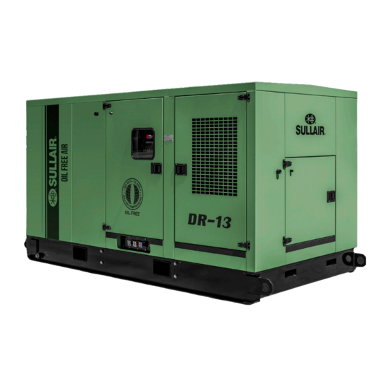
Summarization of Contents
Section 1 Safety
General Safety Precautions
General guidelines for safe operation and compliance with regulations.
Personal Protective Equipment (PPE)
Guidelines on required PPE for operating and maintaining the compressor.
Pressure Release Procedures
Instructions for safely releasing pressure from the system.
Fire and Explosion Hazards
Precautions to prevent fire and explosion risks.
Moving Parts Safety
Guidelines to avoid injury from moving components.
Hot Surfaces, Sharp Edges, and Corners
Warning about contact with hot surfaces and sharp parts.
Toxic and Irritating Substances
Precautions for handling potentially hazardous substances.
Electrical Shock Prevention
Safety measures to prevent electrical hazards.
Safe Lifting Practices
Procedures for safely lifting and moving the compressor.
Entrapment Hazards
Safety measures to prevent entrapment within the enclosure.
Section 2 Installation
Mounting of Compressor
Guidelines for placing and securing the compressor package on a foundation.
Ventilation and Cooling Requirements
Selecting a location for proper airflow and managing heat rejection.
Service Air Condensate Piping
Recommendations for installing service air piping and condensate drains.
Shaft Coupling Alignment Check
Procedure for checking shaft coupling alignment and fastener tension.
Fluid Level Check
Instructions for checking the oil level in the sight glass.
Electrical Preparation
Requirements for customer wiring and compliance with codes.
Motor Rotation Check
Procedure for verifying the correct direction of motor rotation.
Section 3 Specifications
Sullair DR-13 Compressor Package Specifications
Technical specifications including dimensions, weight, and operating pressure.
Lubrication Guide
Information on Sullair lubricant and recommended lubricant change intervals.
Section 4 Compressor Systems
Compressor Systems Introduction
Overview of the Sullair DR-13 compressor package and its benefits.
Description of Components
Identification and brief description of major package components.
Compressor Unit Functional Description
Explanation of the two-stage, oil-free rotary screw compressor design.
Air Inlet System Functional Description
Details on the three-stage dry type air filter and its connection.
Load/Unload Capacity Control System Description
Explanation of how the system regulates compressed air supply based on demand.
Cooling and Silencing System Description
How heat exchangers and silencers manage air temperature and noise.
Lubrication System Functional Description
Explanation of how the lube oil system maintains component lubrication.
Buffer Air System Functional Description
How buffer air ensures oil-free operation by maintaining seal pressure.
Section 5 Supervisor II
Supervisor II Control Parameters
Table of sensor functions, prealarm, shutdown, and failure modes.
Section 6 Compressor Operation
General Compressor Operation
Overview of compressor operation and user responsibilities.
Purpose of Controls
Explanation of the function of various controls and indicators.
Supervisor II Operating Parameters Setup
Procedure for setting operating parameters via the Supervisor II.
Initial Start-Up Procedure
Step-by-step guide for the initial startup of the compressor package.
System Status Messages
Explanation of messages displayed by the Supervisor II indicating status or faults.
Subsequent Start-Up Procedure
Checks to perform for start-ups after initial installation.
Shutdown Procedure
How to properly shut down the compressor package.
Section 7 Maintenance
General Maintenance Overview
Introduction to the minimal maintenance requirements for the compressor.
Daily Operation Checks
Routine checks to perform during daily operation.
Initial Maintenance (50 Hours)
Required maintenance after the first 50 hours of operation.
Maintenance Every 8000 Hours
Scheduled maintenance tasks for 8000-hour intervals.
Maintenance Every 16000 Hours
Scheduled maintenance tasks for 16000-hour intervals.
Optional Diagnostic Service
Description of the Sullair diagnostic service for compressor condition.
Parts Replacement and Adjustment Procedures
Guidelines for replacing parts and making adjustments.
Air Filter Inspection/Maintenance
Procedures for inspecting and maintaining the air filter element.
Oil Filter Maintenance
Procedure for replacing the oil filter element.
Control Line Filter Maintenance
Procedure for replacing the control line filter element.
Inlet Control Solenoid Valve Maintenance
Maintenance procedures for the inlet control solenoid valve.
Solenoid Valve (02250119-220) Maintenance
Maintenance for a specific solenoid valve model.
Solenoid Valve (02250044-392) Maintenance
Maintenance for a different solenoid valve model.
Control Pressure Regulator Maintenance
Procedure for maintaining the control pressure regulator.
Sump Breather Filter Maintenance
Procedure for inspecting and replacing the sump breather filter element.
Oil Sump Strainer Maintenance
Procedure for servicing the oil pump suction strainer.
Blowdown Valve Maintenance
Procedure for maintaining the blowdown valve.
Drive Coupling Maintenance
Inspection and servicing of the drive coupling's flexible element.
Section 8 Troubleshooting
Troubleshooting Introduction
Overview of troubleshooting information based on operational experience.
Troubleshooting Guide
Table of symptoms, probable causes, and remedies for common problems.
Calibration Procedures
How to calibrate Supervisor II pressure and temperature probes.
Section 9 Illustrations and Parts List
Procedure for Ordering Parts
Instructions on how to order replacement parts from Sullair.
Recommended Spare Parts List
List of recommended spare parts for annual and insurance maintenance.
Compressor, Motor and Frame
Illustration and list of parts for the compressor, motor, and frame assembly.
Air Inlet System
Illustration and list of parts for the air inlet system.
Cooler Assembly
Illustration and list of parts for the cooler assembly.
LP Hot & LP Cold Components
Illustration and list of parts for the LP hot and LP cold piping.
HP Discharge Components
Illustration and list of parts for the HP discharge system.
Lube System Components
Illustration and list of parts for the lubrication system.
Electrical Box Components
Illustration and list of parts for the electrical box.
Control System/Condensate Drain
Illustration and list of parts for the control system and condensate drain.
Canopy Components
Illustration and list of parts for the compressor canopy.
Decals
Illustration and list of various warning and identification decals.
Decal Locations
Diagrams showing the placement of decals on the compressor.
Wiring Diagram
Schematic showing the electrical connections for the compressor.


Need help?
Do you have a question about the DR-13 Series and is the answer not in the manual?
Questions and answers