Sign In
Upload
Download
Table of Contents
Contents
Add to my manuals
Delete from my manuals
Share
URL of this page:
HTML Link:
Bookmark this page
Add
Manual will be automatically added to "My Manuals"
Print this page
×
Bookmark added
×
Added to my manuals
Manuals
Brands
Sullair Manuals
Air Compressor
DR13 125H
Operator's manual and parts list
Sullair DR13 125H Operator's Manual And Parts List
Industrial air compressor, 100-200 hp
Hide thumbs
1
2
Table Of Contents
3
4
5
6
7
8
9
10
11
12
13
14
15
16
17
18
19
20
21
22
23
24
25
26
27
28
29
30
31
32
33
34
35
36
37
38
39
40
41
42
43
44
45
46
47
48
49
50
51
52
53
54
55
56
57
58
59
60
61
62
63
64
65
66
67
68
69
70
71
72
73
74
75
76
77
78
79
80
page
of
80
Go
/
80
Contents
Table of Contents
Troubleshooting
Bookmarks
Table of Contents
Table of Contents
General
Personal Protective Equipment
Pressure Release
Fire and Explosion
Moving Parts
Hot Surfaces, Sharp Edges and Sharp Corners
Toxic and Irritating Substances
Electrical Shock
Lifting
Entrapment
Mounting of Compressor
Ventilation and Cooling
Service Air Condensate Piping
Shaft Coupling Alignment Check
Fluid Level Check
Electrical Preparation
Motor Rotation Check
Sullair Dr
Lubrication Guide
Introduction
Description of Components
Compressor Unit
Air Inlet System, Functional Description
Load/Unload Capacity Control System, Functional Description
Cooling and Silencing System, Functional Description
Lubrication System, Functional Description
Buffer Air System, Functional Description
Introduction
Keypad
Status Displays
Lamp Indicators
Operating Parmeter Set
Operating the Compressor
Supervisor II Output Relays
Supervisor II Control Parameters
General
Purpose of Controls
Supervisor II Operating Parameters
Initial Start
System Status Messages
Subsequent Start
Shutdown Procedure
General
Daily Operation
Initial Maintenance after 50 Hours of Operation
Diagnostic Service (Optional)
Parts Replacement and Adjustment Procedures
Air Filter Inspection/Maintenance
Oil Filter Maintenance
Control Line Filter Maintenance
Inlet Control Solenoid Valve Maintenance
Sump Breather Filter Maintenance
Introduction
Solenoid Valve (02250119
Troubleshooting
Calibration
Solenoid Valve (02250044
Procedure for Ordering Parts
Recommended Spare Parts List
Compressor, Motor and Frame
Air Inlet System
Cooler Assembly
Lp Hot & Lp Cold
Hp Discharge
Lube System
Electrical Box
Control System/ Condensate Drain
Canopy
Decals
Decal Locations
Wiring Diagram
Advertisement
Quick Links
1
Table of Contents
2
General
3
Troubleshooting
Download this manual
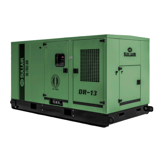
INDUSTRIAL
AIR COMPRESSOR
100---200 HP
Preliminary
DR---13
OPERATOR'S
MANUAL AND
PARTS LIST
REFERENCE
Part Number
02250116---296
ESullair Corporation
Copy
2006
KEEP FOR
FUTURE
Table of
Contents
Previous
Page
Next
Page
1
2
3
4
5
Advertisement
Table of Contents
Need help?
Do you have a question about the DR13 125H and is the answer not in the manual?
Ask a question
Questions and answers
Related Manuals for Sullair DR13 125H
Air Compressor Sullair DE-18 User Manual
Oil-free air compressor tier iii series 1550 cfm (102 pages)
Air Compressor Sullair DE-18 Series Operator's Manual And Parts List
Oil-free air compressor 1500 cfm (52 pages)
Air Compressor Sullair DR-13 Series Operator's Manual And Parts List
Industrial air compressor, 100-200 hp (80 pages)
Air Compressor Sullair DLQ185AC User Manual
Caterpillar portable air compressor (78 pages)
Air Compressor Sullair 125 User Manual
Portable air compressor (62 pages)
Air Compressor Sullair 125 Operator's Manual
Portable (131 pages)
Air Compressor Sullair 3007 Operator's Manual And Parts List
Industrial air compressor air-cooled standard & 24 kt, 3000v, 3700v, 4500v, 30, 37 & 45 kw / 40, 50 & 60hp; 3000 series; 3700 series; 4500 series (80 pages)
Air Compressor Sullair LS25S-250 Operation & Maintenance Manual
Stationary screw compressor (54 pages)
Air Compressor Sullair 300HH User Manual
Portable air compressors (74 pages)
Air Compressor Sullair 3000P User Manual
Industrial air compressor (73 pages)
Air Compressor Sullair ES-6 series Operator's Manual And Parts List
Rotary screw air compressor (57 pages)
Air Compressor Sullair 1800 User Manual
18, 22 & 30kw/25 & 30 & 40hp, industrial (71 pages)
Air Compressor Sullair LS16T Operators Manual And Parts Lists
Industrial air compressor. 100-200hp/ 75-149kw supervisor ii (113 pages)
Air Compressor Sullair LS-120 series Operators Manual And Parts Lists
Industrial air compressor. 40, 50, 60, 75 & 100hp/ 37, 45, 56 & 75kw air-cooled & water-cooled std & 24kt (130 pages)
Air Compressor Sullair ES-6 5H Operator's Manual And Spare Parts List
Rotary screw air compressor es--6 series standard & 24kt 5, 7.5 and 10hp 4, 5.5 and 7.5 kw (78 pages)
Air Compressor Sullair ES-8-15L Operator's Manual And Spare Parts List
Es-8 series. rotary screw air compressor. standard and basic models 15, 20, 25 and 30 hp 11, 15, 18.5 and 22kw (86 pages)
This manual is also suitable for:
Dr-13 series
Dr13 100h
Dr13 125hh
Dr13 150h
Dr13 200h
Dr13 150hh
...
Show all
Dr13 200hh
Dr13 75h
Dr13 75hh
Dr13 90hh
Dr13 90h
Dr13 110h
Dr13 132h
Dr13 110hh
Dr13 132hh
Table of Contents
Save PDF
Print
Rename the bookmark
Delete bookmark?
Delete from my manuals?
Login
Sign In
OR
Sign in with Facebook
Sign in with Google
Upload manual
Upload from disk
Upload from URL


Need help?
Do you have a question about the DR13 125H and is the answer not in the manual?
Questions and answers