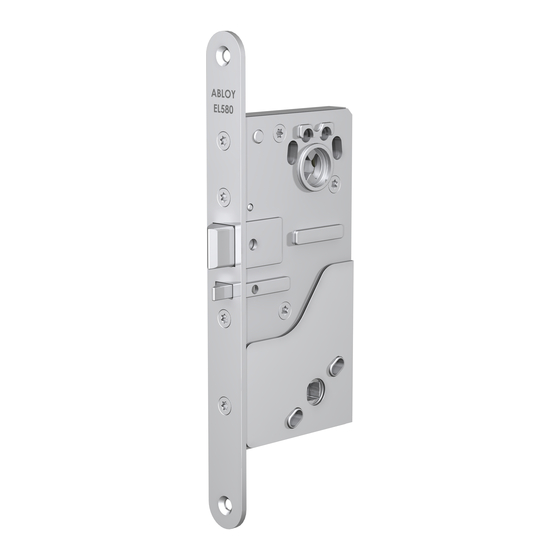
Summarization of Contents
Adjustable Lock Functions
Mechanical Function Options
Configuration options for mechanical aspects like handle direction and bolt throw.
Electrical Function Options
Configuration options for electrical functions, including solenoid operation.
Status Feedback and Indications
Information on status indications for deadlock and handle operation.
Fire Door Installation Requirements
Important notes regarding installation on fire doors, including bolt throw settings.
Product Standards and Certifications
Safety and Exit Device Standards
Details product compliance with EN 179, EN 1125, and EN 1634-1 safety standards.
Electromagnetic Compatibility (EMC)
Information regarding electromagnetic compatibility requirements as per EN 61000 standards.
Fire Door and General Certifications
Certifications for fire door applications and product codes.
Installation Requirements for Safety Standards
EN 179 Emergency Exit Device Installation
Specific installation details and force limits for EN 179 emergency exit devices.
EN 1125 Panic Exit Device Installation
Specific installation details and force limits for EN 1125 panic exit devices.
Modification Restrictions
Important warnings against unauthorized modifications to the product.
Electrical Wiring and Connections
Wiring Diagram Overview
Diagrams illustrating electrical connections for the lock.
Integrated Protection Diodes
Information on built-in protection diodes and maximum values for microswitches.
Handle Position Control Warning
Warning against using handle position feedback for lock control in certain systems.
Drilling Schemes and Dimensions
Lock Case Drilling Patterns
Detailed drilling patterns for various lock case models.
Backset and Dimension Specifications
Specifications for backset length and other critical dimensions.
Wire Routing Space
Recommended space for routing electrical wires.
Assembly and Adjustment Procedures
Assembly Step A: Plate Installation
Instructions for installing the mounting plate.
Assembly Step B: Mechanism Adjustment
Instructions for adjusting internal lock mechanisms.
Lock Case Adjustments
Mechanism Adjustment Sequence
Step-by-step guide for adjusting lock case components.
Bolt Throw Adjustment for Fire Doors
Specific instructions for adjusting bolt throw on fire doors.
Handle Side Configuration
Mechanical vs. Electrical Handle Sides
Configuration of mechanical and electrically controlled handle sides.
Allen Screw Installation
Instructions for installing the Allen screw for handle control.
Lock Model Variations and Installation
EL580/EL582 Oval Handle Installation
Installation details for EL580/EL582 models with oval handles.
EL580/EL582 Standard Handle Installation
Installation details for EL580/EL582 models with standard handles.
PE580 Handle Installation
Installation details for the PE580 model.
Product Material and Recycling
Material Composition for Recycling
Information on materials requiring separate recycling, including electronics.
Product Alteration Disclaimer
Statement reserving the right to make alterations to products.


Need help?
Do you have a question about the PE580 and is the answer not in the manual?
Questions and answers