Table of Contents
Advertisement
User's
Manual
Integral Flowmeter
(AXW###)
Remote Transmitter
(AXG1A)
Remote Transmitter
(AXFA11G)
This manual outlines the basic guidelines for installation and
wiring procedures. For the items which are not covered in this
manual, read the user's manuals and the general specifi ca-
tions as listed in Table 1.1.
For explosion protection type, also read the applicable user's
manual as listed in Table 1.1.
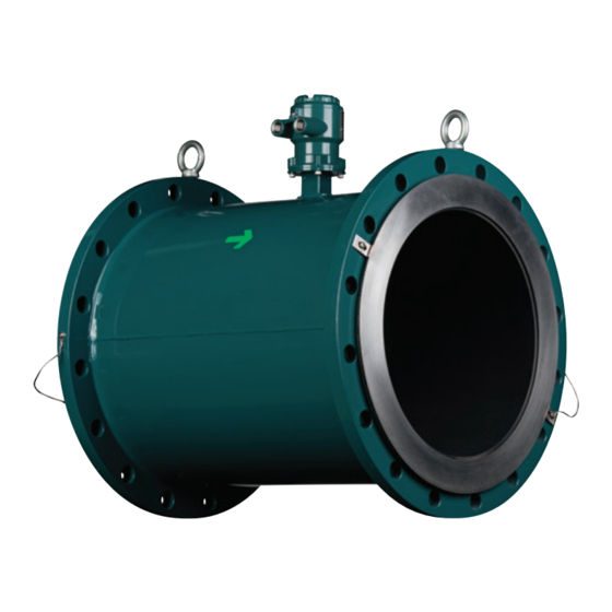
ADMAG TI Series
AXW Magnetic Flowmeter
AXW Magnetic Flowmeter
[Size: 25 to 400 mm (1 to 16 in.)]
Installation Manual
Contents
1.
2.
3.
Remote Sensor
(AXW###)
4.
Remote Transmitter
(AXW4A)
5.
6.
7.
1.1
For Safe Use of Product ................................................3
1.2
Warranty .........................................................................6
1.3
Transmitter .....................................................................6
2.1
Model and Specifi cations Check ...................................7
2.2
Storage Precautions ......................................................8
3.1
Piping Design Precautions ............................................9
3.2
Handling Precautions ...................................................11
3.2.1
General Precautions .......................................11
3.2.2
Flowmeter Piping ........................................... 12
3.3
3.3.1
Wafer Type .................................................... 13
3.3.2
Flange Type ................................................... 18
3.3.3
Gasket Size(customer pipe) .......................... 24
3.4
Remote Transmitter Installation .................................. 25
3.4.1
Installation Location ....................................... 25
3.4.2
Mounting of AXW4A Transmitter ................... 25
3.4.3
Mounting of AXG1A Transmitter .................... 25
3.4.4
Mounting of AXFA11 Transmitter ................... 26
3.5
Changing Direction of Cable Entry ............................. 26
3.6
Changing Direction of Display Unit ............................. 27
4.1
Wiring Precautions ...................................................... 29
4.2
Cables ......................................................................... 30
4.3
Cable Entries .............................................................. 31
4.4
Flowmeter and Remote Transmitter ........................... 35
4.5
Transmitter (Sensor Side) ........................................... 42
4.6
Input and Output ......................................................... 45
5.1
Operation by Display unit ............................................ 48
5.2
Display and Basic Confi guration ................................. 48
5.3
Display Mode and Setting Mode ................................. 51
5.4
Parameter Setting from Display Panel ....................... 52
5.5
microSD Card Setting ................................................. 53
5.6
BRAIN Confi guration Tool ........................................... 54
5.7
HART Confi guration Tool ............................................ 54
5.8
Modbus Confi guration Tool ......................................... 55
5.9
fi eldbus Confi guration Tool ..................... 56
6.1
Pre-operation Zero Adjustment ................................... 57
6.2
Zero Adjustment from Display Unit ............................. 57
6.3
Hardware Switch Setting ............................................ 58
IM 01E24A01-01EN
4th Edition
IM 01E24A01-01EN
1
2
3
4
5
6
7
Advertisement
Table of Contents

Related Manuals for YOKOGAWA AXW Series


Summarization of Contents
1. Introduction
1.1 For Safe Use of Product
Provides essential safety precautions and guidelines for product handling, installation, and operation.
1.2 Warranty
Details the warranty period and conditions for product repair or replacement.
1.3 Combination for Remote Sensor and Remote Transmitter
Specifies compatible combinations for remote sensors and transmitters, ensuring proper system integration.
2. Receiving and Storage
2.1 Model and Specifications Check
Instructions for verifying product model, suffix codes, serial numbers, and specifications upon receipt.
2.2 Storage Precautions
Guidelines for storing the product to maintain its condition and prevent damage before installation.
3. Installation
3.1 Piping Design Precautions
Key considerations for designing piping systems to ensure accurate measurements and prevent sensor damage.
3.2 Handling Precautions
Safety measures and procedures for safely handling the flowmeter during installation and maintenance.
3.3 Integral Flowmeter and Remote Sensor Installation
Detailed steps for installing integral flowmeters and remote sensors, including wafer and flange types.
3.4 Remote Transmitter Installation
Procedures for mounting the remote transmitter on pipes or walls for optimal operation.
3.5 Changing Direction of Cable Entry
Instructions for modifying the cable entry direction for transmitters and terminal boxes.
3.6 Changing Direction of Display Unit
Procedure for rotating the display unit to improve visibility and access.
4. Wiring
4.1 Wiring Precautions
Essential safety guidelines and procedures to follow when performing wiring operations.
4.2 Cables
Specifications and recommendations for various cables used for power, signal, and communication.
4.3 Cable Entries
Information on selecting and installing appropriate cable glands for watertight and secure connections.
4.4 Connecting to External Products of Integral Flowmeter and Remote Transmitter
Detailed wiring procedures for connecting power supply, signals, and communication interfaces.
4.5 Connecting to Remote Sensor and Remote Transmitter (Sensor Side)
Instructions for wiring the remote sensor to the transmitter, covering terminal configurations and diagrams.
4.6 Input and Output
Descriptions of output signal types (current, pulse, status) and input signals for system integration.
5. Basic Operating Procedures
5.1 Operation by Display unit
How to configure parameters and operate the flowmeter using the IR switches on the display unit.
5.2 Display and Basic Configuration
Overview of display elements, status icons, data indication, and basic configuration settings.
5.3 Display Mode and Setting Mode
Procedure for switching between display and setting modes, and accessing different operational levels.
5.4 Parameter Setting from Display Panel
Step-by-step guide for setting various parameters like flow rate units, span, and tag numbers.
5.5 microSD Card Setting
Instructions for using the microSD card for parameter storage, backup, and restoration.
5.6 BRAIN Configuration Tool
Connecting and using the BRAIN configuration tool for device parameter setting via BRAIN communication.
5.7 HART Configuration Tool
Connecting and using the HART configuration tool for device parameter setting via HART communication.
5.8 Modbus Configuration Tool
Details on connecting and configuring the Modbus configuration tool for Modbus communication.
5.9 FOUNDATION Fieldbus Configuration Tool
Information on connecting and using the FOUNDATION Fieldbus configuration tool for device setup.
6. Operation
6.1 Pre-operation Zero Adjustment
Procedure for performing zero adjustment before operation to ensure accurate flow measurement.
6.2 Zero Adjustment from Display Unit
Step-by-step guide to execute zero adjustment using the flowmeter's display unit and IR switches.
6.3 Hardware Switch Setting
Instructions for setting hardware switches for burnout, write protect, simulation, and line termination.
7. Errors and Countermeasures (Display unit)
Explanation of NE107 status
Defines NE107 status codes (Failure, Check, Specification, Maintenance, No Effect) for error messages.
System Alarm
Lists system alarms indicating device breakdown or abnormal measurement requiring attention.
Process Alarm
Details process alarms that occur during normal operation but affect measurement accuracy.
Setting Alarm
Describes parameter setting errors that do not affect normal operation but require configuration adjustments.
Warning
Lists warnings indicating normal operation but potential issues that may require attention.
Need help?
Do you have a question about the AXW Series and is the answer not in the manual?
Questions and answers