YOKOGAWA AQ6370D Getting Started Manual
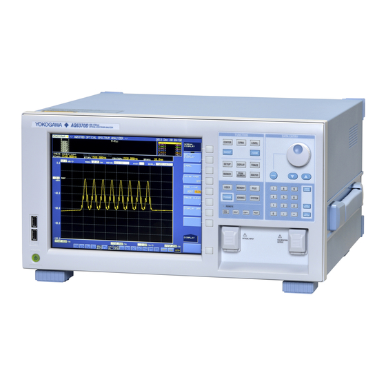
Optical spectrum analyzer
Hide thumbs
Also See for AQ6370D:
- User manual (219 pages) ,
- User manual (445 pages) ,
- User manual (240 pages)

Related Manuals for YOKOGAWA AQ6370D


Summary of Contents for YOKOGAWA AQ6370D
- Page 1 User’s Manual AQ6370D Optical Spectrum Analyzer Getting Started Guide IM AQ6370D-02EN 4th Edition...
-
Page 2: Product Registration
Product Registration Thank you for purchasing YOKOGAWA products. YOKOGAWA provides registered users with a variety of information and services. Please allow us to serve you best by completing the product registration form accessible from our website. http://tmi.yokogawa.com/ PIM 103-04E... -
Page 3: List Of Manuals
List of Manuals The following manuals, including this one, are provided as manuals for the AQ6370D. Please read all manuals. Manual Title Manual No. - Page 4 Revisions • 1st Edition: April 2014 • 2nd Edition: May 2016 • 3rd Edition: May 2017 • 4th Edition: October 2017 IM AQ6370D-02EN...
-
Page 5: Checking The Contents Of The Package
2 Already attached to the optical input of the AQ6370D front panel. 3 Already attached to the calibration light source output of the AQ6370D front panel. For products whose suffix code contains “Z,” an exclusive manual may be included. - Page 6 Manual CD The English directory in the manual CD contains the PDF files shown below. The CD also contains Japanese manuals. File Name Manual Title Manual No. IMAQ6370D-01EN AQ6370D Optical Spectrum Analyzer IM AQ6370D-01EN User’s Manual IMAQ6370C-17EN AQ6370C/AQ6370D/AQ6373/ IM AQ6370C-17EN AQ6373B/AQ6375/AQ6375B Optical Spectrum Analyzer Remote Control User’s Manual...
-
Page 7: Safety Precautions
This manual is an essential part of the product; keep it in a safe place for future reference. YOKOGAWA assumes no liability for the customer’s failure to comply with these requirements. The following symbols are used on this instrument. - Page 8 To prevent the possibility of electric shock or fire, be sure to use the power cord supplied by YOKOGAWA. The main power plug must be plugged into an outlet with a protective earth terminal. Do not disable this protection by using an extension cord without protective earth grounding.
- Page 9 Vérifier l’alimentation Avant de brancher le cordon d’alimentation, vérifier que la tension source correspond à la tension d’alimentation nominale du AQ6370D et qu’elle est compatible avec la tension nominale maximale du cordon d’alimentation. Utiliser le cordon d’alimentation et la fiche adaptés Pour éviter tout risque de choc électrique ou d’incendie, toujours utiliser le cordon...
- Page 10 être extrêmement dangereux. Ne pas retirer le capot, ni démonter ou modifier l’instrument Seul le personnel YOKOGAWA qualifié est habilité à retirer le capot et à démonter ou modifier l’instrument. Certains composants à l’intérieur de l’instrument sont à haute tension et par conséquent, représentent un danger.
- Page 11 Laser Class 1 Label Information about the Laser Light Source Used Class Laser Type Wavelength Maximum Diameter of Repetation Numerical Output Power Mode Field Rate Aperture EE-LED 1.53 µm 0.04 mW 9 µm AQ6370D-01, -10, -20 AQ6370D-02, -12, -22 IM AQ6370D-02EN...
-
Page 12: Sales In Each Country Or Region
With reference to the equipment types in the WEEE directive, this product is classified as a “Monitoring and control instruments” product. When disposing of products in the EU, contact your local Yokogawa Europe B.V. office. Do not dispose in domestic household waste. -
Page 13: Conventions Used In This Manual
Note Calls attention to information that is important for proper operation of the instrument. IM AQ6370D-02EN... - Page 14 Bold characters used in the procedural explanations indicate characters that are marked on the panel keys or the characters of the soft keys displayed on the screen menu. Unit k: Denotes “1000.” Example: 100 kS/s K: Denotes “1024.” Example: 459 KB (file data size) IM AQ6370D-02EN...
-
Page 15: Flow Of Operation
The figure below is provided to familarize the first-time user with the general flow of this instrument operation. For a description of each item, see the relevant section or chapter of the user’s manual, IM AQ6370D-01EN. Preparing for Measurement Installing the Instrument Section 3.1... -
Page 16: Table Of Contents
Panel Keys and Knobs ......................3 LCD Screen ..........................6 Installing the Instrument ......................8 Attaching the Connector Adapter ...................11 Connecting the Device ......................14 Turning the Power ON/OFF ....................16 Connecting the DUT ......................22 Replacing Fuses ........................25 11 Specifications .........................26 External Dimensions ......................29 IM AQ6370D-02EN... -
Page 17: Front Panel
(when the built-in light source specification is -L1) COPY Save the screen as an image file. PRESET Clears all internal settings of the AQ6370D except for the remote interface (ETHERNET, GP-IB, and RS232) settings. IM AQ6370D-02EN... -
Page 18: Rear Panel
Rear Panel Rear Panel AQ6370D-02, A6370D-12, A6370D-22 2 3 4 AQ6370D-01, A6370D-10, A6370D-20 2 3 4 Name Function GP-IB GP-IB port for controlling this unit through an external computer TRIGGER IN Input connector for synchronous signals for the synchronous measurement function with the Tunable Laser... -
Page 19: Panel Keys And Knobs
The TRACE key contains functions related to trace mode settings. MARKER The MARKER key contains functions related to markers. PEAK SEARCH The PEAK SEARCH key contains functions for searching for peaks and bottoms in measured waveforms. ANALYSIS The ANALYSIS key contains functions related to measured waveform analysis. IM AQ6370D-02EN... - Page 20 When you press the COPY key, the measured waveforms and lists displayed on the screen are output to the internal printer or a file. PRESET The PRESET key clears all internal settings of the AQ6370D except for the remote interface (ETHERNET, GP-IB, and RS232) settings. UNDO/LOCAL The key’s function changes depending on the status of the instrument when the UNDO/...
- Page 21 (right-most) character is removed, allowing entry of the correct character. By holding the BACK SPACE key down, you can erase the entire entry in the numeric keypad input area and make the numeric keypad input area disappear, returning it to the condition preceding numeric keypad input. IM AQ6370D-02EN...
-
Page 22: Lcd Screen
Displays the statuses of main settings (When a setting is ON, its display is depressed, or is displayed with white on black background if the display colors are black and white.) Displays wavelength axis scale per DIV Displays sweep status (RPT=Repeat; SGL=Single; STP=Stop) IM AQ6370D-02EN... - Page 23 4 LCD Screen Function Displays soft key menu (Displays markers and data analysis results.) Parameter display area Parameter input area OVERVIEW display screen (Only displayed when ZOOM function is used.) Displays sub-scale (Displayed when resolution calibration is executing.) IM AQ6370D-02EN...
-
Page 24: Installing The Instrument
La lumière infrarouge est toujours émise depuis le connecteur de sortie optique. Ne regardez jamais directement dans le connecteur de sortie optique. La lumière infrarouge risquerait de gravement vous blesser ou de provoquer une perte de vision. IM AQ6370D-02EN... - Page 25 Also be sure to maintain sufficient clearance for connecting measurement cables. 20 cm or more 20 cm or 20 cm or 20 cm or more more more Inlet holes (also on the bottom panel) IM AQ6370D-02EN...
- Page 26 When removing dirt from the case or operation panel, disconnect the power to the circuits under test and the instrument, remove the instrument’s power cord from the power outlet, then wipe gently with a clean, dry cloth. Do not use volatile chemicals since this might cause discoloring and deformation. IM AQ6370D-02EN...
-
Page 27: Attaching The Connector Adapter
La lumière infrarouge est toujours émise depuis le connecteur de sortie optique. Ne regardez jamais directement dans le connecteur de sortie optique. La lumière infrarouge risquerait de gravement vous blesser ou de provoquer une perte de vision. IM AQ6370D-02EN... - Page 28 On products with the /FC, /SC, /RFC, or /RSC option, connector adapters come attached to the optical input and calibration light source output on the AQ6370D front panel. On products without these options, attach a connector adapter appropriate for the optical connector.
- Page 29 SC type The optical input connector adapter (AQ9447) comes in the following two types. FC type SC type Optical Connectors Types The instrument can use FC, or SC type optical connectors. FC type optical SC type optical connector connector IM AQ6370D-02EN...
-
Page 30: Connecting The Device
• In addition to a USB keyboard, the USB interfaces can be used to connect USB storage and a USB mouse. For information on operations using the keyboard, see section 4.2 of the User’s Manual, IM AQ6370D-01EN. IM AQ6370D-02EN... - Page 31 Connect the USB storage device to the USB connector on the front panel of the instrument. USB connector Removing See section 8.1 of the User’s Manual, IM AQ6370D-01EN. (Using the REMOVE USB STORAGE soft key.) CAUTION Do not remove the USB storage device or turn the power OFF while the USB storage device access indicator is blinking.
-
Page 32: Turning The Power On/Off
• Pour éviter les risques de choc électrique ou d’incendie, utilisez toujours le cordon d’alimentation fourni par YOKOGAWA et prévu pour l’instrument. • Veillez à raccorder l’instrument à la terre pour éviter tout risque de choc électrique. - Page 33 8 Turning the Power ON/OFF Preparing to Turn ON the Power The AQ6370D has a MAIN POWER switch for turning the main power ON/OFF, and a POWER switch for starting and shutting down the instrument. The POWER switch is a push-button switch;...
- Page 34 Turn ON the MAIN POWER switch on the rear panel of the instrument. The POWER switch on the front panel of the instrument lights orange. AQ6370D-02, -12, -22 AQ6370D-01, -10, -20 Press the POWER switch on the front panel of the instrument. The color of the switch turns from orange to green.
- Page 35 If an error occurs in the memory or Some other part of the instrument during Initialization, the AQ6370D will stop running with "STEP @ / 9" showing on the screen (where @ is a number between I and 9).
- Page 36 YES and NO soft keys. Press the YES soft key. The message, “AQ6370D is shutting down. Please wait...” appears, and shut-down begins. If you do not wish to shut down, press the NO soft key.
- Page 37 If the shutdown procedure was not performed after the previous session, the following message appears after start up. Failure to properly shut down the instrument can result in damage to the monochromator. When turning OFF the power, always perform the shut down procedure. Press any key to clear this message. IM AQ6370D-02EN...
-
Page 38: Connecting The Dut
• Avant de connecter la lumière d’entrée, vérifiez qu’elle ne dépasse la valeur nominale maximale de l’analyseur AQ6370D, car si tel était le cas, la section optique pourrait être endommagée. • Appuyez fermement le connecteur optique sur la surface nettoyante du nettoyeur. - Page 39 NORM and ANGLED. Set ANGLED if the optical fiber under test is APC (angle lap PC). Otherwise, set NORMAL. Note • If you set FIBER CONNECTOR to ANGLED, is displayed in the measurement conditions area. • The instrument's measurement accuracy specification is for when FIBER CONNECTOR is set to NORM IM AQ6370D-02EN...
- Page 40 Clean the top of the optical connector on the other end of the optical fiber with a fiber cleaner. Connect the optical connector on the other end of the optical fiber to the optical connector on the DUT. Measuring System AQ6370D Light source Optical fiber IM AQ6370D-02EN...
-
Page 41: Replacing Fuses
Replacing Fuses There is a fuse inside the instrument. However, you should not replace the fuse yourself. It could indicate additional internal damage. If you believe the fuse is blown, please contact your nearest YOKOGAWA dealer. IM AQ6370D-02EN... -
Page 42: Specifications
Specifications For the specifications of the limited model (SUFFIX --02, -01), see IM AQ6370D-51EN, a manual specifically for the limited model (SUFFIX -02, -01). Item Specifications Applicable fiber SM (9.5/125 µm), MMF (50/125 µm, 62.5/125 µm), Large core size fibers (core diameter of up to 200 μm) - Page 43 -L1) or an external light source Wavelength Calibration Auto wavelength calibration using built-in calibration light source (when the built-in light source specification is -L1) or an external light source Resolution calibration User-defined resolution calibration using an external light source (DFB-LD) IM AQ6370D-02EN...
- Page 44 10: When applying a HeNe laser (1523 nm), resolution: 0.1 nm, 1520 nm to 1620 nm (excluding peak wavelength ± 2 nm). 11: When using the Yokogawa signal mode fiber with our standard Angled PC connector, it is 15 dB(Typ.) when using the PC connector.
-
Page 45: External Dimensions
External Dimensions Unit : mm (approx. inch) AQ6370D-02, AQ6370D-12, AQ6370D-22 AQ6370D-01, AQ6370D-10, AQ6370D-20 REAR VIEW ( 0.58 ) 14.8 458.8 ( 18.06 ) ( 1.26 ) 12.3 12.3 ( 0.48 ) ( 16.77 ) ( 0.48 ) If not specified, the tolerance is ±3%. However, in cases of less than 10 mm, the tolerance is ±0.3 mm.
Need help?
Do you have a question about the AQ6370D and is the answer not in the manual?
Questions and answers