Table of Contents
Advertisement
Quick Links
Advertisement
Table of Contents
Troubleshooting

Related Manuals for CAS CAUW220


Summary of Contents for CAS CAUW220
- Page 2 Notation Conventions This instruction manual uses the following notation conventions to indicate Safety Precautions and additional information. Indicates a potentially hazardous situation that may result in injury to personnel or equipment damage. Provides additional information needed to properly use the balance. Other conventions used in this manual include: Item Description...
-
Page 3: Safety Precautions
This includes areas where the balance is expose to dust or flammable gases and liquids. Use the AC adapter specified by CAS. To prevent electric shock, never disassemble the AC adapter. The AC adapter is designed for indoor use. Do not use the AC adapter in exterior environments or where it may be splashed by water. - Page 4 Declaration Of Conformity CAS Corporation declares that the following products: CAUW-D Series, CAUW Sreies, CAUX Series and CAUY Series Analytical Balances conform to the following directives. Directives EMC directive 89/336/EEC amended by 92/31/EEC, 93/68/EEC EN55022: 1994 / A1: 1995 / A2: 1997 (Class A)
- Page 6 The controls implemented as a result of security related requirements are intended to result in trusted records. CAS CLASS-Balance Agent CAS provides a means for compliance with 21 CFR Part 11 with CAS CLASS-Balance Agent software, part of a comprehensive laboratory data management system, CAS CLASS Agent.
-
Page 7: Table Of Contents
Contents Notation Conventions Safety Precautions ......................12 1. Introduction ............13 2. Component Names and Functions 2.1 Main Components .....................13 2.2 Key Panel and Operation...................14 2.3 Balance Display and Functions.................15 ......................16 3. Specifications ......................17 4. Installation 4.1 Installation Site....................17 4.2 Unpacking and Delivery Inspection..............18 4.3 Installation ......................20 4.4 Turning On the Power ..................22 4.5 Span Calibration....................23... - Page 8 7.4.2 Returning to Default Settings (Menu reset) .........40 7.4.3 Menu Lock.....................41 8. Setting the Built-in Clock ..........42 (CAUW-D/CAUW/CAUX series only) 8.1 Date........................42 8.2 Date Output Style....................43 8.3 Time ........................44 ....................45 9. Display Settings 9.1 Bar Graph Display .....................45 9.2 Changing the Minimum Display (CAUW/CAUX/CAUY series only)..46 9.3 Turning the Backlight On and Off (CAUW series only) (Not for CAUW-D)47 ......................48 10.
- Page 9 ..................65 11. Environment Settings 11.1 What are environmental settings?..............65 11.2 Settings for Stability and Response ..............65 11.2.1 Standard mode ..................65 11.2.2 Anti-convection mode .................65 11.2.3 High-stability Mode................66 11.2.4 Pouring Mode (fast response).............66 11.3 Stability Detection Band..................68 11.4 Zero Tracking....................69 .........................70 12.
- Page 10 ..............96 15. Maintenance and Transport 15.1 Maintenance.....................96 15.2 Transpor......................98 ....................99 16. Troubleshooting 16.1 Error Code Displays ..................99 16.2 Troubleshooting .....................100 ........................101 Appendices A-1. Menu map ......................101 A-2. Standard Accessories and Maintenance Parts List ........105 A-3. Special Accessories (Options) List...............105 A-4. Specifications for RS-232C Connector............106 A-5.
-
Page 11: Introduction
1. Introduction Thank you for choosing the CAS CAUW-D/CAUW/CAUX/CAUY Series analytical balance. CAS confidently offers this high-performance analytical balance, the result of over 80 years of experience in manufacturing precision balances. While providing rapid and accurate mass measurement, reliability has been improved even more by employing the UniBloc cell, introduced for use in electronic balances by CAS in 1989. -
Page 12: Component Names And Functions
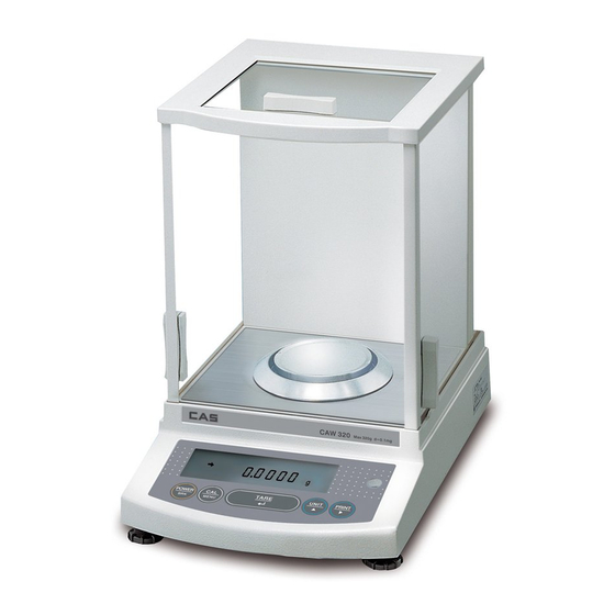
2. Component Names and Functions 2.1 Main Components Read these pages before installation Data I/O connector Keyboard connector RS-232C connector DC IN connector Theft prevention ring For chains or other Below-weigh hook cover Ground terminal attachments. attachment screw... -
Page 13: Key Panel And Operation
2.2 Key Panel and Operation The following is a list of the functions for each key. During Measurement Pressed once and released Pressed and held for about 3 seconds Switches between the operation Switches the key notification [POWER] and standby modes. buzzer on/off. -
Page 14: Balance Display And Functions
2.3 Balance Display and Functions Bar graph display section Units display section Bar graph display section (Some of the symbols and characters on the balance display are not used by this balance.) Display Name Description Indicates that the weighed value is stable. Stability mark In menu selection, indicates the currently selected item. -
Page 15: Specifications
3. Specifications CAUW-D series Series name CAUW series CAUX Series CAUY series (Dual range type) Model name CAUW220D CAUW120D CAUW320CAUW220CAUW120CAUX 320CAUX220CAUX120 CAUY220 CAUY120 Capacity 220g/82g 120g/42g 320g 220g 120g 320g 220g 120g 220g 120g Minimum display 0.1mg/0.01mg 0.1mg/0.01mg 0.1mg 0.1mg 0.1mg 0.1mg 0.1mg... -
Page 16: Installation
4. Installation 4.1 Installation Site (1) Power Requirements Select an installation site that is near a power source to allow the use of the attached AC adapter or a site where the special accessory battery pack can be properly used. Verify that the power voltage conforms to that indicated on the AC adapter. -
Page 17: Unpacking And Delivery Inspection
• Sites with extreme temperature changes, or high/ low temperature, or high/low humidity. • Sites near flammable of corrosive gases • Sites with dust, electromagnetic waves, or magnetic fields Install on a sturdy and level tabletop. Stone is recommended. Rather than the middle of the room, the edges and corners are generally appropriate for vibration-free measurement. - Page 18 Verify that there has been no damage and that the following standard packing items are present. Contact your local distributor in case of damaged or missing items. Standard packed items and quantity Standard packed items quantity Balance main body Pan supporter Anti-draft ring AC adapter Adapter cable holder...
-
Page 19: Installation
4.3 Installation Attach the adapter cable holder. Peel the protective sheet of adhesive off the adapter cable holder, and stick it on the back of the balance as shown in the figure. Place the balance main body on the installation site. Attach the pan supporter, the pan, and the antidraft ring. - Page 20 Attach the In-use protective cover. When the key panel and the display must be protected from dirt and wear, place the cover over the key panel.
-
Page 21: Turning On The Power
4.4 Turning On the Power Insert the AC adapter plug in to the DC IN connector on the back of the balance. Place the AC adapter cable as shown in figure and hold it with the adapter cable holder. Plug the AC adapter to the power outlet. Clip After the balance performs a self check, calibration will be automatically executed. -
Page 22: Span Calibration
4.5 Span Calibration After installation, be certain to complete warm up and span calibration. During span calibration, the balance must be left in a very stable condition. To do this, leave the power on at standby (warm up) for an hour or more before performing calibration. - Page 23 For CAUY Series Span calibration with external weights . Leave the pan with nothing on, in g display mode. Press the [CAL] key once. “E-CAL” will be displayed. (Example) Press the [O/T] key. The zero display will blink. Stability is confirmed after about 30 seconds and the value of the weight that should be loaded will blink.
-
Page 24: Basic Operation
5. Basic Operation (Read Chapters 1 to 5 for basic but proper operation of the balance.) Before using the balance, warm up thoroughly (at least one hour) and calibrate. When intending to use the CAUW-D series in the small range (minimum display 0.01mg), warm it up for at least four hours. - Page 25 Except when placing or removing items or calibration weights to and from the weighing chamber, keep the glass doors closed unless otherwise described in this manual. Air convection causes measurement error if the temperatures of the weighed item and the chamber are different. In order to avoid this, equalize the temperatures by leaving the item in the extra space within the chamber before weighing.
-
Page 26: Changing The Unit Display
5.2 Changing the Unit Display Pressing the [UNIT] key switches display between the registered units, piece counting and specific gravity measurement modes. The units other than 'g', 'pcs', '%' and 'ct' are not registered in the default settings. The units to be used must be registered as described in 12.Units. If the power is turned off and turned on again, the weighing unit will be 'g'. -
Page 27: For Stable Measurement In Semi-Micro Range(Cauw-D Series Only)
5.4 For Stable Measurement in Semi-micro Range (CAUW-D series only) The small range (semi-micro range, minimum display 0.01mg) of CAUW-D series dual range balances produces excellent response and stability. However, weighing in the 0.01mg range is generally more subject to the environment and how measurements are performed compared to the 0.1mg range. - Page 28 Avoid the location where vibration from any machinery is transmitted. Corners of a room are less subject to influence of vibration. Do not use the door of the room. Do not allow other people enter, exit or move in the room. Open glass door minimum.
-
Page 29: Windowsdirect Function
6.2 WindowsDirect Settings Simple settings are made for the balance and the computer. Connection is by RS-232C cable specified by CAS If bi-directional communication software is used: WindowsDirect function should be turned off. Set up the optimal communication parameters for the software according to “14.3 Communication setting”. -
Page 30: Connecting The Rs-232C Cable
When data is outputted to the computer by WindowsDirect function, the effect is the same as “typing the numerical value displayed on the balance and pressing Enter key on the computer’s keyboard”. If you wish the effect of “pressing → key” instead of “pressing Enter key”on the computer’s keyboard”, select “SEtwin -”... -
Page 31: Setting Up The Computer
When using WindowsDirect, use a Null modem cable of one of the below wirings. D-sub9 D-sub25 D-sub9 D-sub25 A cable of hte (1) wiring is available as an optional accessory. RS-232C Cable 25P-9P (1.5m) P/N 321-60754-01 6.2.3 Setting Up the Computer (leave the balance unplugged) Turn ON the power to the computer and start Windows®*. - Page 32 Put a check mark at “Support Serialkey device” in the “General” tab. This should be the only check mark on all the tabs of Accessibility Options unless “Administrative options” appears in the “General” tab. Put check marks at both the items of “Administrative options”...
-
Page 33: Start And Checking Operation
6.2.4 Start and Checking Operation Start Windows®. After Windows® has completely started, connect power cable from the AC adapter to the balance, when “oFF” is displayed, press the [POWER] key. The mass display appears. Turning ON the balance before Windows®* is completely activated may cause incorrect operation. -
Page 34: Troubleshooting Windowsdirect Function
CAS does not guarantee that this function can be used on all computers without any problems currently or in the future. ( CAS is not liable for any direct or indirect problems caused by this function. It is recommended that important data or programs on your computer be backed-up before using this function. - Page 35 When the WindowsDirect Function Intermittently Malfunctions: Use a communication speed of 300bps. Depending on the processing ability of the computer, this function may operate incorrectly if communication speed is too high. Send the next data only after the current one is displayed on the screen. Depending on the processing ability of the PC, this function may operate incorrectly if the interval of data transmission is too short.
-
Page 36: Menu Item Selection
7. Menu Item Selection 7.1 What is a menu? The CAUW-D/CAUW/CAUX/CAUY series is equipped with many useful functions. The menu is provided to allow the operator to efficiently select the functions that meet the operator’s objectives. Understand the menu procedures to gain full command of the functions provided in the CAUW-D/CAUW/CAUX/CAUY series. -
Page 37: Menu Item Selection Procedures
7.3 Menu Item Selection Procedures See the menu map (Appendix A-1). The CAUW-D/CAUW/CAUX/CAUY series menu consists of four levels with the most often used menus in the first level for an easy-to-use structure. The menu can be entered by pressing the [CAL] key from the mass display. The menu operation keys for movement in the menu tree are shown in the following table. - Page 38 Mass display (Example) Execute the preset calibration method (see 10.2, 10.3.1) WindowsDirect setting (down) (see 6.2.1) WindowsDirect setting (right) (see 6.2.1) (Example) Settings check display (see 7.4.1) Standard mode Pouring mode Settings for Stability and Response (see 11.2) Anti-convection mode High-stability mode Entry to second level (application measurement, individual settings menu group)
-
Page 39: Useful Functions Related To Menu
7.4 Useful Functions Related to Menu 7.4.1 Settings Check Display From mass display, press the [CAL] key four times to display the confirmation of the current settings. Displayed as abbreviations are the three kinds of environmental settings (see 11.), ON/OFF for the fully-automatic span calibration(see 10.3.2,10.3.3), and ON/OFF for the GLP/GMP/ISO compliant calibration report output.(see 10.4.1) The weight symbol appears when either or both of the fully-automatic span calibration PSC or Clock-CAL are on. -
Page 40: Menu Lock
7.4.3 Menu Lock The menu setting operations can be locked so that the settings cannot be inadvertently changed. This is called Menu Lock. Windows Direct settings also lock. The menu lock is set with the following procedure. How to lock the menu Connect the balance to the power and wait. -
Page 41: Setting The Built-In Clock (Cauw-D/Cauw/Caux Series Only)
8. Setting the Built-in Clock (CAUW-D/CAUW/CAUX series only) CAUW-D/CAUW/CAUX series are installed with a built-in clock. set the clock before use of Clock-CAL (10.3.3) or Calibration report (10.4.1) functions. Note that the current time is displayed during STANDBY mode (4.4). 8.1 Date From the mass display, press the [CAL] key repeatedly until “SEttinG”... -
Page 42: Date Output Style
8.2 Date Output Style The order of the year, the month and the date in the external output can be selected from three styles. From the mass display, press the [CAL] key repeatedly until “SEttinG” appears, press the [O/T] key. “CAL dEF” will appear. Press the [CAL] key repeatedly until “StyL. -
Page 43: Time
8.3 Time From the mass display, press the [CAL] key repeatedly until “SEttinG” appears. Press the [O/T] key. “CAL dEF” will appear. (Example) Press the [CAL] key repeatedly until “t-HH.MM” appears (HH and MM are each (2:25PM) two digits representing hour and minute, respectively), and press the [O/T] key. -
Page 44: Display Settings
9. Display Settings 9.1 Bar Graph Display This function displays a bar graph representation of the load on the pan. This may be used to prevent sudden appearance of “oL” (overload) during measurement. This bar graph display can be turned on or off. Setting ON/OFF Press the [CAL] key repeatedly from the mass display and when “Func.SEL”... -
Page 45: Changing The Minimum Display (Cauw/Caux/Cauy Series Only)
9.2 Changing the Minimum Display (CAUW/CAUX/CAUY series only) The CAUW/CAUX/CAUY series allow the minimum display to be changed by one digit if desired. The last decimal place will be rounded and removed from the display. (To change the minimum display by one digit) Press the [1d/10d] key from the mass display. -
Page 46: Turning The Backlight On And Off (Cauw Series Only) (Not For Cauw
9.3 Turning the Backlight On and Off (CAUW series only) (Not for CAUW-D) The CAUW series is equipped with a backlight for the display to allow easy viewing Regardless of the surrounding lighting conditions. The backlight can be switched on and off. Press the [CAL] key repeatedly from the mass display until “SEttinG”... -
Page 47: Calibration
10. Calibration 10.1 What is calibration? 10.1.1 The Necessity of Calibration Calibration is required to accurately weigh items with an electric balance. Calibration must be performed in these conditions: When the location of the installation site is changed (even when moved within the same room). When the room temperature changes. -
Page 48: Types Of Calibration
10.1.2 Types of Calibration Terms used in this manual: Span calibration ..Adjustment of the balance sensitivity using two weight values, zero and near-capacity Calibration test ..Comparing the current calibration mass reading to the calibration mass reading after the last span calibration. Calibration .. -
Page 49: Executing Calibration
10.2 Executing Calibration Perform calibration only after correct installation and thorough warm up. Also, make sure that nothing is on the pan and ensure conditions free from the influence of vibrations or wind. 10.2.1 Span Calibration With Built-in Weight (CAUW-D/CAUW/CAUX series only) “i-CAL”... -
Page 50: Span Calibration With External Weights
10.2.2 Span Calibration With External Weights “E-CAL” (The balance will be adjusted with external calibration weights) From the mass display, press the [CAL] key once. If the display shows “E CAL” (Preset calibration method is “E-CAL”), jump to Step 4. If the display shows another item (Preset calibration method is not “E-CAL”), go on to Step 2. -
Page 51: Calibration Check With Built-In Weight
10.2.3 Calibration Check With Built-in Weight (CAUW-D/CAUW/CAUX series only) “i-tESt” (The balance is checked with the built-in weight but not adjusted.) From the mass display, press the [CAL] key once. If the display shows “i tESt” (Preset calibration method is “i-tESt”), jump to Step 5. -
Page 52: Calibration Check With External Weights
10.2.4 Calibration Check With External Weights “E-tESt” (The balance is checked with external calibration weights but not adjusted.) From the mass display, press the [CAL] key once. If the display shows “E tESt” (Preset calibration method is “E-tESt”), jump to Step 5. If the display shows another item (Preset calibration method is not “E-tESt”), go on to Step 2. -
Page 53: Calibration Settings
10.3 Calibration Settings One of the following four calibration methods listed in the below step 3 is selected as “preset calibration method”. Preset calibration method will be called with only one key touch from the mass display for convenience of frequent use. Select your most frequently used method here. -
Page 54: Psc Fully-Automatic Span Calibration (Cauw-D/Cauw/Caux Series Only)
10.3.2 PSC Fully-automatic span calibration (CAUW-D/CAUW/CAUX series only) Using a temperature sensor, this function performs fully-automatic span calibration with the built-in weight when a significant temperature change is detected. If PSC turned ON, when there is a temperature change that would influence sensitivity, span calibration executes automatically to maintain the sensitivity of the balance. - Page 55 Setting PSC ON/OFF From mass display, press the [CAL] key repeatedly until “SEttinG” appears. Press the [O/T] key to display “CAL dEF”. (Example) Press the [CAL] key repeatedly until “PSC:**” Setting appears. The ** positions show the current check (When ON) setting, either “on”...
-
Page 56: Clock-Cal Fully-Automatic Span Calibration (Cauw-D/Cauw Series Only)57
10.3.3 Clock-CAL Fully-automatic span calibration (CAUW-D/CAUW series only) The balance can be set to execute fully-automatic span calibration at set times (up to three times a day) with the built-in weight and the built-in clock. Clock-CAL is a very convenient function, when calibration reports are desired for regular calibrations, or to schedule span calibrations during break times to avoid interruption of measurement work. - Page 57 Setting the time for Clock-CAL From mass display, press the [CAL] key repeatedly until “SEttinG” appears. Press the [O/T] key to display “CAL dEF” Press the [CAL] key repeatedly until “tCAL t*” (Example) appears. Press the [O/T] key to display “t* HH:MM”.
-
Page 58: Pcal: Calibration Of The Built-In Weight
10.3.4 PCAL: Calibration of the Built-in Weight (CAUW-D/CAUW/CAUX series only) The built-in calibration weight is already calibrated before shipping but the operator can also calibrate the built-in calibration weight using their own external calibration weights. The calibration of the built-in calibration weight is called PCAL. Inputting the conventional mass value (s) of the operator’s calibration weight (s) can provide the most accurate span calibration (refer to 10.3.6). -
Page 59: Inputting External Calibration Weight Value For E-Cal
10.3.5 Inputting External Calibration Weight Value for E-CAL The exact value (conventional mass value) of the operator’s calibration weight to be used for E-CAL and E-tESt procedures can be entered. From mass display, press the [CAL] key repeatedly until “SEttinG” appears. Press the [O/T] key. -
Page 60: Inputting External Calibration Weight Value For Pcal
10.3.6 Inputting External Calibration Weight Value for PCAL The exact value (conventional mass value) of the operator’s calibration weight to be used for PCAL procedure can be entered. From mass display, press the [CAL] key repeatedly until “SEttinG” appears. Press the [O/T] key. -
Page 61: For Glp/Gmp/Iso Compliance
10.4 For GLP/GMP/ISO Compliance 10.4.1 Calibration Report Setting Setting the calibration report provides an automatic calibration record output every time span calibration or calibration test is performed. An optional electronic printer (see 14.1) can save reports by printing them. Combination with Clock-CAL function (see 10.3.3) provides fully- automatic and periodical calibration and reports. -
Page 62: Balance Id Setting
Date output, ID number etc. of electronic printer EP-50 or EP-90 should be Turned off when calibration report is produced. 10.4.2 Balance ID Setting This setting is for the balance ID number that is output along with the calibration report. From mass display, press the [CAL] key repeatedly until “SEttinG”... -
Page 63: Date Printout Setting
10.4.3 Date Printout Setting This setting determines whether or not the date and time on the balance’s built-in clock is printed out along with the calibration report. From mass display, press the [CAL] key repeatedly until “SEttinG” appears. Press the [O/T] key. “CAL dEF” appears. (Example) Press the [CAL] key repeatedly until “Prtdt:**”... -
Page 64: Environment Settings
11. Environment Settings 11.1 What are environmental settings? The response and other settings can be changed to adapt to the installation environment (for example, unavoidable vibrations or air currents) or measurement uses (for example, depending on whether solid objects, liquids, or powders are to be measured). 11.2 Settings for Stability and Response Generally, signal processing for greater stability slows the response and processing for higher response reduces stability. -
Page 65: High-Stability Mode
Anti-convection mode adjusts the timing of Settings Check Display appearance of the stability mark. Note that when Anti-convection mode is selected, the stability mark will take longer to appear. From the mass (When anti-convection display, press the [CAL] key repeatedly until mode is selected) “ConvECt”... - Page 66 Environmental setting menu Or, press [CAL] key once or twice to display “StAbL.Env” (for very stable environmental condition) or “UnStb.Env” (for unstable environmental condition). (when normal is selected) Pressing [O/T] key at each display will select that environmental setting. It is recommended to set “StAbL.Env” or “UnStb.Env”...
-
Page 67: Stability Detection Band
11.3 Stability Detection Band The appearance of the Stability Mark ( ) indicates that the mass display has been stabilized. The condition for judging stability is user-selectable. When the stability detection band is set to 1, the stability mark appears when the mass display stays within 1 count for a set period of time. -
Page 68: Zero Tracking
11.4 Zero Tracking Using the zero tracking function allows the display to be kept at the current zero point by automatically canceling slight drifts from the zero point caused by environmental conditions. When measuring very slow change in mass such as liquid droplets and evaporation processes, it is recommended to turn zero tracking OFF. -
Page 69: Units
12. Units The CAUW-D/CAUW/CAUX/CAUY series allow display of various mass units. Units that are registered beforehand can be called by simply pressing the [UNIT] key when in mass display. The default units are gram, percentage, PCS, and carat. In order to use the other units included in the CAUW-D/CAUW/CAUX/CAUY series, register the units beforehand according to section 12.1. - Page 70 Menu display Units or function Reference “U-g”. g (gram) “U-mg” mg (milligram) “U-%” percentage conversion See 12.2 “U-PCS” piece counting See 13.1 “U-ct” ct (carat) “U-,d” solid specific gravity measurement See 13.2 “U-d” liquid density measurement See 13.3 “U-mom” monme* “U-Lb”.
-
Page 71: Percentage (%) Conversion
12.2 Percentage (%) Conversion Setting a standard sample to 100% allows percentage conversions. (Example) Register percentage unit beforehand. (See 12.1.) Percentage unit is registered by default. (When % is used for the first time) Therefore, registrantion is not required if the default setting has not been changed. -
Page 72: Application Functions
13. Application Functions 13.1 Piece Counting (PCS) Register PCS as one of the units beforehand. (Example) (See 12.1.) PCS is registered by default. Therefore, registration is not required if the (When PCS is used for the first time) default setting has not been changed. (Example) From the mass display, press the [UNIT] key repeatedly to switch to the PCS display. -
Page 73: Solid Specific Gravity Measurement
13.2 Solid Specific Gravity Measurement Solid specific gravity measurement computes the density (or specific gravity) of a solid sample by measuring its weight in air and in a liquid of known density (or specific gravity). The following is the procedure when using a hanging pan, a tank and a table allowing below balance weighing, prepared by the operator. - Page 74 Pressing the [UNIT] key repeatedly from the mass display switches the display to “,d”. Note that “g” also appears during weight measurement in air. Press the [O/T] key. (Example) Place the items to be measured on the pan. When the stability mark appears, press the (Example) [CAL] key.
-
Page 75: Liquid Density Measurement
13.3 Liquid Density Measurement Liquid density measurement computes the density of a liquid by measuring the weight of a sinker (solid) with a known volume in air and in the liquid. The following is the procedure when using a hanging pan, a tank and a table allowing below balance weighing, prepared by the operator. - Page 76 Pressing the [UNIT] key repeatedly from the mass display switches the display to “d”. Note that“g” also appears during weight measurement in air. Press the [O/T] key. (Example) Place the sinker on the balance pan. When the stability mark appears, press the [CAL] key.
-
Page 77: Auto Print
13.4 Auto Print Using Auto Print allows measurement results to be automatically output via the RS-232C connector or DATA I/O connector without pressing the [PRINT] key with every measurement. This function can be combined with WindowsDirect (see 6.). When Auto Print is activated, if a sample weighing 10 counts or more is placed on the pan while the mass displayed is within ±5 counts of zero, the result is output via the RS-232C cable or DATA I/O connector automatically upon display stabilization. -
Page 78: Interval Timer (Cauw-D/Cauw/Caux Series Only)
13.5 Interval Timer (CAUW-D/CAUW/CAUX series only) This function automatically outputs the measurement values of the balance at set time intervals. (Example) Press the [CAL] key repeatedly from the mass display until “FUnC.SEL” appears. Press the [O/T] key to display “CAL”. Press the [CAL] key repeatedly until “int”... -
Page 79: Add-On Mode
No more than one of the four application modes, Auto Print (13.4), Interval Timer (13.5), Add-on Mode (13.6), Formulation Mode (13.7), can be set ON at the same time. The [O/T] key can always be used for taring. In interval timer standby status, pressing the [POWER] key puts the balance in power standby status. - Page 80 Press the [CAL] key repeatedly from the mass display until “FUnC.SEL” appears. Press the [O/T] key. The display will show “CAL”. Press the [CAL] key repeatedly until “Addon: **” appears. The “**” shows the current setting, “on” for on, “oF” for off. Press the [O/T] key.
-
Page 81: Formulation Mode
13.7 Formulation Mode This function is convenient for making many measurements of minute samples and seeking the total mass. In this mode with any unit, when a sample is placed on the pan and [PRINT] key is pressed, that value is output via the RS-232C cable or DATA I/O connect and automatic taring is performed each time afterwards. - Page 82 (Operating Formulation Mode) When the Formulation Mode is set on, the add-on symbol and the Memory symbol are illuminated in the mass display. In the Formulation Mode, place the container (if used) on the pan and press [O/T] key to tare. (Taring is accepted only before weighing the first sample.) Place the sample (first component) in the...
- Page 83 When Formulation mode is in use, fully-automatic span calibration by PSC (10.3.2) or Clock-CAL (10.3.3) is not performed. Instead, Weight symbol ( ) keeps blinking when span calibration is necessary. Span calibration can be performed between sets of measurements.
-
Page 84: Communication With Peripheral Devices
14. Communication with Peripheral Devices 14.1 Electronic Printer The CAU-C series allows connection to the following CAS electronic printers. EP-80 Electronic Printer EP-50 / EP-50WIN Electronic Printer EP-60A Electronic Printer When using an electronic printer, follow the below procedure for connecting it to the balance. -
Page 85: Personal Computer - Rs-232C
14.2 Personal Computer - RS-232C Programming with the command codes makes it possible to control the balance from a computer. When the balance does not have to be controled by the computer, WindowsDirect (see 6.) offers very handy data transmission. 14.2.1 Connecting the Cable The cable must have the correct connections as shown in the diagram below. -
Page 86: Data Format
14.2.2 Data Format Data format 1 (“F-dF1” in menu item selection) is the CAS’s standard data format. (See 14.3.3.5) The following is the details of this data format. (1) Basic format An example of data format for a negative weight value (-21.6865g) with delimiter of C/R is shown. - Page 87 (iii) When the delimiter “C/R+L/F” is selected (Refer to 14.3.3.2) The delimiter information requires one more character. Therefore one more byte is added after Position No.13 in the above example. Consequently, the data becomes 1 byte longer. (3) Data format in case of “oL” or “-oL” (Overload) The below is the data format for “oL”.
-
Page 88: Command Codes
14.2.3 Command Codes Inputting characters and command codes not shown here into the balance may not only alter the previous settings but may also impair proper measurement. If by mistake characters or commands not shown here are entered into the balance, immediately unplug the power supply cable and wait about ten seconds before plugging it in again. - Page 89 ct unit registry Monme unit registry SDENCE Solid specific gravity registry LDENCE Liquid specific gravity registry 100% setting g, % switching g unit removal - mg mg unit removal - PERCENT % unit removal - PCS Piece counting removal - CT ct unit removal - MOM Monme unit removal...
-
Page 90: Communication Settings
14.3 Communication Settings 14.3.1 What are communication settings? These settings are menu item selections for determining communication specifications when connecting to devices such as an electronic printer or a computer. The settings here are effective for both RS-232C and DATA I/O communication specifications. When a printer or another device is connected to the DATA I/O connector, set the balance communication settings to “Standard Setting 1”. -
Page 91: User Setting
Selecting one of standard Settings) From the mass display, press the [CAL] key repeatedly until the [intFACE] display appears. Press the [O/T] key. The display shows “iF;F1” If necessary, press the [CAL] key repeatedly (When F1 is selected) until the desired standard setting display appears. Then, press the [O/T] key. - Page 92 14.3.3.1 Communication speed settings (1) The display changes from “io.b:****” to “b-300”. Pressing the [CAL] key cycles through the available settings. The stability mark ( ) appears, when the current setting is displayed. Display during b-300 b-600 b-1200 b-2400 b-4800 setting 300bps 600bps...
- Page 93 Data format 2. Data format 3. Data format 4. Data format 1. Extended Same format Same format Setting specifics Standard CAS format from as Mettler as Sartorius format. data format 1. balances. balances. (2) When the desired setting appears, press the [O/T] key.
-
Page 94: Decimal Point Symbol In Output Data
14.3.3.6 Handshake settings (1) The display changes from “io.H: ****” to “F-dF1”. to “H-oFF”. Pressing the [CAL] key cycles through the available settings. The stability mark ( ) appears, when the current setting is displayed. Display during H-oFF H-Soft H-HArd H-tr setting Software... -
Page 95: Maintenance And Transport
15. Maintenance and Transport 15.1 Maintenance Cleaning Clean by wiping with a soft cloth soaked in neutral detergent and wrung tightly. The pan can be washed in water. Dry it thoroughly before attaching it to the balance. The side glass doors can be removed to allow cleaning and replacement of the door rail. Never use organic detergents and chemicals or chemical wiping cloths, as they may damage the coating and the display panel. - Page 96 Slide the glass door out backwards. In the CAUW-D/CAUW/CAUX/CAUY series, when the door rails of the side glass doors become dirty or worn, the rails can be replaced. Removing the door rail Remove the glass door. Press down the outer edge of the door rail with a pointed thing for lifting the door rail.
-
Page 97: Transpor
15.2 Transport When moving by hand … Remove the anti-draft ring, the pan, and the pan supporter from the weighing chamber. Lift the main body as shown in the figures and carry it securely in both hands. When using other methods of transport …... -
Page 98: Troubleshooting
16. Troubleshooting 16.1 Error Code Displays Error code display Description Countermeasures Remove items from the pan. The zero point shift is In order to postpone calibration, CAL E2 large during calibration. press [POWER] key. CAL E3 Large span error in PCAL Use the correct calibration weight. Large span error in CAL E4 Use the correct calibration weight. -
Page 99: Troubleshooting
16.2 Troubleshooting When Symptom Possible Causes Countermeasures The AC adapter is not securely connected. Before Nothing appears The power switchboard Check power supply measurement in the display. of the room is turned off. and connect correctly. The power voltage is incorrect. Change the installation site. -
Page 100: Appendices
Automatic span Severe temperature Move to a location with calibration executes variations in the room less temperature frequently. or the instrument fluctuation. Span calibration has Perform correct span not been done. calibration. The mass display is Press the [O/T] key to incorrect. - Page 101 0.0000 Mass Display ( 10.2, 10.3.1) Excuting preset calibration method ( 10.2.1) Mass Display i CAL (Ex.) (Displays the preset calibration method.) ( 6.2.1) Mass Display SEtwin| WindowsDirect Setting (Down) ( 6.2.1) Mass Display SEtwin- WindowsDirect Setting (Right) ( 6.2.1) ( 6.2.1) St.
- Page 102 ( 13.4) AtPrt: on Autoprint function ( 13.4) ¡ Ap-on Ap-oF ( 13.5) *1,*5 Interval timer setting ( 13.5) ¡ ( 9.1) AdiSP: on Bar graph display setting ( 9.1) ¡ Ad-on Ad-oF ( 13.6) Addon:on Add-on mode ( 13.6) ¡...
- Page 103 Date, time printout ( 10.4.3) ( 10.4.3) Prtdt: on ¡ Date, time printout on Prtdt-on Date, time printout off Prtdt-oF Decimal point symbol in ( 14.4) output data ( 14.4) dECPt: Pr ¡ ".": Period dECPt-Pr ",": Comma dECPt-Cn rESEt Menu reset ( 7.4.2) ( 7.4.2) ¡...
-
Page 104: A-2. Standard Accessories And Maintenance Parts List
A-2. Standard Accessories and Maintenance Parts List Part name Part number Remarks 321-41225 Pan supporter assembly 321-62933 With rubber cushions Anti-draft ring 321-62903 AC adapter Contact your distributor Level screw 321-62884 Glass door assembly (right) 321-62932-02 Includes handle Glass door assembly (left) 321-62932-01 Includes handle Glass door assembly (top) -
Page 105: A-4. Specifications For Rs-232C Connector
The number and specifications noted here are subject to change without notice. The RS-232C cables are not guaranteed to match every computer or device. Also, their lock screws may not match the connector threads on the balance. A-4. Specifications for RS-232C Connector RS-232 Specifications Pin number Name... -
Page 106: A-5. Table Of Unit Conversion Constants
A-5. Table of Unit Conversion Constants The following conversions are used to display in various mass units. = 1000 mg = 5 ct = 0.266667 mom = 0.00220462 Lb = 0.0352740 Oz = 0.0321507 Ozt = 0.0267173 TL-HK = 0.0264555 TL-Singapore = 0.0266667 TL-Taiwan = 0.0264600 TL-Malaysia = 0.0266071 TL-China... -
Page 107: A-6. Performance Check Guide
A-6. Performance Check Guide The following is a standard guideline used to determine whether the balance is working properly. The specific criterion can be set according to each user’s requirements. Conduct the performance check in a location without changes in room temperature. - Page 108 Compute Rx and Ry according to the expressions given above. Rx and Ry values within 1.0mg are normal. (In the small range of CAUW-D series, within 0.30mg. ) Cornerload Performance (four-corner error) For CAUW-D series, conduct this check in the large range. Warm up the balance thoroughly.
-
Page 109: A-7. Below-Weigh Hook Dimensions
A-7. Below-weigh Hook Dimensions (Unit: mm) sensor Below-weigh hook Balance bottom Below-weigh hook... -
Page 110: A-8. Index
A-8. Index ..........22, 44 current time AC adapter ........19, 22, 105 ..........105 accessories ..........87 data format ........15, 81 add-on mode date ..........42, 43, 64 ..........65 air currents DC IN connector ........13, 22 analog display bar graph display decimal point ........ - Page 111 percentage ..........72 performance check ........108 peripheral ..........12, 85 Inputting external calibration weight value 60, 61 peronal computer computer ¡ installation .........17, 20, 48, 50 personal computer .........30, 86 interval timer ..........79 piece counting ..........73 ......... 21 in-use protective pouring mode ..........
- Page 112 ............44, 58 time ..........79 time interval .............98 transport ........17, 23, 65, 66 vibration ......35, 99, 101 troubleshooting ..35 troubleshooting WindowsDirect function ........49 types of calibration warm up ....22, 23, 25, 50, 55, 59, 109 warm-up ............. 47 weighing chamber .....13, 20, 25, 96 unit ............27, 70 weighing range...
- Page 113 [Explanatory Operation Sheet] Key Switch Basic Functions Key functions during basic weighing (Refer to main manual 2.2 for details) [POWER] Switches between operation and stand-by (On/Off). [CAL] Enters calibration or menu item selection. [O/T] Tares the balance (Displays zero with a container on the pan) [UNIT] Switches weighing units.
- Page 114 Faster Response for Filling If faster response is required for filling or dosing purpose, select Pouring mode. The response will be very fast, but display will be unstable. How to set pouring mode (From mass display) Press [CAL] key repeatedly till “Pouring” is displayed → Press [O/T] key →...
- Page 115 Hints on Fully-automatic Span Calibration Fully-automatic span calibration PSC (Not with CAUY series) (Refer to 10.3.2 for detail.) Default setting of PSC is ON. Upon detection of temperature change, span calibration is automatically performed to maintain accuracy. Weight symbol ( ) blinks prior to fully- automatic calibration.
- Page 116 Span Calibration Procedure Span calibration is required to accurately weigh items with an electronic balance. Span calibration should be performed: When the location of the balance is changed, even within the same room. When the room temperature changes considerably. Periodically, according to the quality control plan of the user. Before span calibration, verify that the balance is in the mass-display and that the pan is empty.
- Page 117 MEMO...
Need help?
Do you have a question about the CAUW220 and is the answer not in the manual?
Questions and answers