
Related Manuals for Kverneland NGH 401


Summary of Contents for Kverneland NGH 401
- Page 1 NGH 301-351-401 NGS 301-401-451 Instruction manual Edition 06/2014 Print 06/2014 Language from machine number Article code MUM78EN08...
- Page 2 Telefono +39 059 380 511 Copyright owned by Kverneland Group Modena, ITALY. All copying, transcription to other media, translation and use of extracts or parts is pro- hibited without the express authorization of Kverneland. All right reserved. The contents of this instruction manual are subject to modifcation with-...
-
Page 3: Table Of Contents
Contents Contents Introduction ......4 Universal seed drill attachment About this manual Hydraulic seed drill attachment Meaning of symbols Accord seed drill triangular mounting frame... -
Page 4: Introduction
Introduction Introduction Introduction About this manual This Instruction Manual is addressed to qualified users or experienced agricultural operatives who have received suitable training on the use of the machine. For your safety Before hitching up or operating the machine, please familiarise yourself with the contents of this Instruction Manual. -
Page 5: Safety
Safety Safety Safety For your safety This section contains general safety warnings. The individual sections of manual contain additional specific safety warnings which are not included in this section. Take particular care to observe the safety warnings • for your own personal safety •... - Page 6 Safety Safety Switch off the engine and remove the starter key Before proceeding with any maintenance or repair operations, first switch off the engine and remove the key from the starter switch, then consult the instruction manual Adhesive label code: ZD75500711 Keep clear of moving parts Rotating parts hazard.
-
Page 7: Positions Of The Safety Warning Labels
Safety Safety Positions of the safety warning labels Sound pressure levels Microphone1 Microphone 2 height of measurement Measured values Tractor only Tractor+implement open open Microphone 1 92 dB (A) 96 dB (A) Microphone 2 92 dB (A) 94 dB (A) -
Page 8: Lifting
Safety Safety Lifting Observe safety rules! Do not stand under suspended loads Take all necessary precautions to prevent injury or damage caused by accidental falls When using a crane or other lifting equipment, the harrow must be attached at the upper mounting as shown in the figure... -
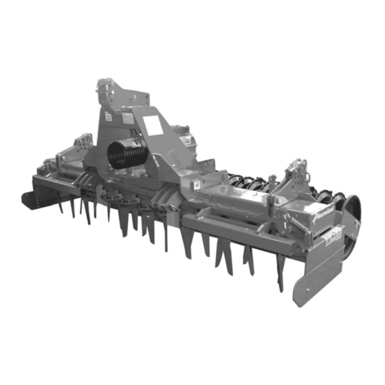
Page 9: Getting To Know Your Machine
• Transmission casing (Ref.1): 3.0m - 12 tine holders - 24 tines (NGH 301 and NGS 301) 3.5m - 14 tine holders - 28 tines (NGH 351) 4.0m - 16 tine holders - 32 tines (NGH 401 and NGS 401) 4.5m - 18 tine holders - 36 tines (NGS 451) -
Page 10: Technical Specifications
Ø500 mm Maximum tractor Working MODEL Type of gearbox packer roller, without drive shaft power width (approx. values) NGH 301 3.00 m 1626 Kg NGH 351 131 kw/ 180 HP exchange speed 3.50 m 1836 Kg NGH 401 4.00 m... -
Page 11: Delivery And Preparation Of The
Delivery and preparation of the machine Delivery and preparation of the machine Delivery and preparation of the machine Checking the On delivery, check that all parts of the machine are present and that they have not been damaged in transit; notify your dealer, importer or machine the manufacturer immediately of any defects found. - Page 12 Delivery and preparation of the machine Delivery and preparation of the machine > Support the roller, observing safety rules > Unscrew the nuts securing the arms and remove the bolts Caution: suspended load hazard! > Move the arms and the roller into the correct position (see figure) and replace the bolts >...
-
Page 13: Hitching The Machine
Hitching the machine Hitching the machine We strongly recommend that you observe the safety warnings given Hitching the machine in the previous pages of this manual. The category of the tractor 3-point linkage must match that of the implement. Mounting bracket Mounting bracket for Cat.2 linkage for Cat.2+3 linkage... - Page 14 Hitching the machine Hitching the machine NOTE In working position, the top link of the tractor's hydraulic linkage should slope down towards the tractor (see next figure). This configuration enables the implement to overcome obstacles and ensure that the roller is loaded correctly. Incorrect adjustment (e.g. top and lower links parallel) will result in an excessive load on the implement and the roller.
- Page 15 Hitching the machine Hitching the machine Connection of the drive Proceed as follows: shaft to the harrow > Clean and grease the input shaft of the implement and the internal splines (9) of the universal joint. > Unscrew and remove the screws (10) securing the splined coupling of the drive shaft to the implement input shaft.
-
Page 16: Preparation For Work
Preparation for work Preparation for work Preparation for work Checking the oil We strongly recommend that you observe the safety warnings given in the previous pages of this manual. levels Risk of burns! Beware of hot surfaces and hot oil. Before proceeding, check: •... -
Page 17: Working Speed
Exchange speed gearbox Input Secondary Model Tractor Pto speed (1000 rpm) and working speed shaft shaft Z=23 Z=33 NGH 301 Z=19 Z=37 248 (OPTIONAL) NGH 351 NGH 401 Z=21 Z=35 290 (OPTIONAL) (180 CV) -
Page 18: Speed Selection
Preparation for work Preparation for work Input Secondary Model Tractor Pto speed (1000 rpm) and working speed shaft shaft Z=27 Z=43 NGS 301 Z=23 Z=46 238 (OPTIONAL) NGS 401 NGS 451 Z=30 Z=39 365 (OPTIONAL) (250 CV) Z=33 Z=36 435 (OPTIONAL) Lever operated gear change Input Secondary... - Page 19 Preparation for work Preparation for work to damage the gasket. > Remove the circlips (15) and change the gears according to the indications in the above table. > Carefully install the circlips in their grooves. > Replace the gearbox cover. Check that the gasket is positioned correctly and tighten the cover screws evenly.
-
Page 20: Transporting The Implement On
Transporting the implement on the road Transporting the implement on the road Observe the safety rules! Transporting the implement on the road Particularly those regarding lifting (see Page 8.) Do not exceed the transport width of 3.00 m when transporting the implement on public roads. -
Page 21: Preparations In The Field
Preparations in the field Preparations in the field Preparations in the field Lateral stone The stone guards must be set to the working position: to do this, make sure that the pin (18) that limits movement of the guards is inserted in guards the correct hole and secured with the cotter pin. -
Page 22: Adjustment Of The Levelling Bar
Preparations in the field Preparations in the field Hole Adjustment of the The rear levelling bar serves to level the soil and to contain clods within the working area. levelling bar It should be adjusted in accordance with the position of the roller (see figure below). -
Page 23: Positioning The Track Eradicator
Preparations in the field Preparations in the field Positioning the The track eradicators (27) are mounted on two support bars (28). In the case of the NGH models, these support bars (28) are bolted to the track eradicator frame, while on NGS they form part of the frame itself. The individual track eradicators must be positioned in the centre of the tracks left by the tractor tyres and adjusted to a working depth of approximately 5 cm. -
Page 24: Cleaning, Care And Storage
Cleaning, care and storage Cleaning, care and storage Cleaning, care and storage Safe storage Store the machine in a dedicated storage area away from vehicles, people or animals in transit! Do not allow children to come near or to play on the stored machine! Park the machine so that it is stable! Observe all applicable safety rules when unhitching the machine from the tractor Winter storage... -
Page 25: Maintenance
Maintenance Maintenance Before proceeding with any maintenance work on the machine, it is Maintenance essential to carry out the following operations: • never carry out any work on the machine while it is in operation • the tractor Pto must be disengaged, the engine switched off and the key removed from the starter switch •... - Page 26 Exchange speed gearbox Model Oil type Quantity oil change interval oil change after mineral 6.5 l NGH 301-351-401 EP ISO VG 460 DIN 51517 TEIL 3 CLP 30 h 200 h (PAG) ISO VG 320 DIN NGS 301-401-451 8.0 l...
-
Page 27: Comparative Classification Of Viscosity
Maintenance Maintenance Comparative classification of viscosity Standard AGMA lubricant viscosity viscosity nomenclature gears oil base... -
Page 28: Replacing The Tines Of The Harrow
We recommend that you use only Kverneland original replacement parts. NOTE The tines may continue to be used until they are worn down to half their original length, at which point they should be replaced. -
Page 29: Packer Roller
Maintenance Maintenance Packer roller We strongly recommend that you observe the safety warnings given in the previous pages of this manual. Secure the implement so as to prevent it falling or being lowered accidentally. Adjusting and > Loosen the nuts (38). replacing the >... -
Page 30: Disc Rollers
Maintenance Maintenance Disc rollers We strongly recommend that you observe the safety warnings given in the previous pages of this manual. Secure the implement so as to prevent it falling or being lowered accidentally. Adjusting and replacing the scrapers The disc roller is comprised of large diameter discs combined with a series of shoes and blades mounted on an adjustable bar (43). - Page 31 Maintenance Maintenance spacers (51) may be installed next to the bushes (52). To replace the blades, unscrew the nuts (53), replace the worn blades with new ones (54), fit new self-locking nuts and tighten. To replace the shoes, unscrew the nuts (55), replace the old shoes with new ones, fit new self-locking nuts and tighten.
-
Page 32: Accessories
Accessories Accessories Accessories Universal seed We strongly recommend that you observe the safety warnings given in the previous pages of this manual. drill attachment The universal seed drill attachment with manual height adjustment is indicated for machines with working widths of up to 3 m. Assembly: >... - Page 33 Accessories Accessories • Fit the rings (57) on the seed drill lifting pins and secure them in position with the screws provided. > Attach the tie rod (56) to the upper mounting bracket of the seed drill and adjust it so that the seed drill is in the correct working position. Attachment using brackets with safety cotter pins (Ref.B): •...
-
Page 34: Hydraulic Seed Drill Attachment
Accessories Accessories Hydraulic seed We strongly recommend that you observe the safety warnings given in the previous pages of this manual. drill attachment The maximum load bearing capacity of the hydraulic seed drill attachment is 1550 Kg. 72 78 Assembly: >... - Page 35 Accessories Accessories • Fit the rings (80) on the seed drill lifting pins and secure them in position with the screws provided. > Attach the tie rod (69) to the upper mounting bracket of the seed drill and adjust it so that the seed drill is in the correct working position. Attachment using brackets with safety cotter pins (Ref.B): •...
-
Page 36: Accord Seed Drill Triangular Mounting Frame
Accessories Accessories Accord seed drill We strongly recommend that you observe the safety warnings given in the previous pages of this manual and in the manual supplied with triangular the Accord seed drill. mounting frame Assembly: > Remove the Pto shield on the back of the gearbox. >... -
Page 37: Troubleshooting
Troubleshooting Troubleshooting Troubleshooting Problem Cause Remedy Apply grease as indicated by drive Insufficient lubrication shaft manufacturer Worn trunnion bearings Renew bearings Noise from the drive shaft Adjust length, replacing any Drive shaft length incorrect components cut to wrong length where necessary Apply grease as indicated by drive Insufficient lubrication shaft manufacturer... -
Page 38: Warranty
Your dealer will provide initial information about operation of the machine and will be able to give you any further advice you may require. Your dealer is also in direct contact with KVERNELAND customer service. Should you wish to present a claim to KVERNELAND customer service, it is essential that you provide the following information about your machine. -
Page 39: Disposal Of The Machine
Disposal of the machine Disposal of the machine At the end of its working life, the machine must be disposed of in a Disposal of the machine proper manner. Observe the applicable regulations governing waste disposal. Metal parts All metal parts must be taken to a metals recycling centre. Rubber parts All rubber parts, such hydraulic and pneumatic hoses, should be taken to a specialized recycling centre... - Page 40 EU Conformity Declaration EU Conformity Declaration EU Conformity Declaration In accordance with Kverneland Group Modena EC Directive 2006/42/ Strada Ponte Alto, 74 I 41123 Modena ITALY is solely responsible for the following product conforming to EC Type plate and CE symbol...
-
Page 41: Ec Declaration Of Conformity
Index Index Accessories Oil levels Accord seed drill attachment Adjusting the depth of the rollers Adjustment of the levelling bar Packer roller adjusting and replacing the scrapers Positioning the roller Changing the gearbox oil Positioning the stone guards Checks Preparing the machine for work Connection of the drive shaft Replacing the tines Disc rollers...
Need help?
Do you have a question about the NGH 401 and is the answer not in the manual?
Questions and answers