Table of Contents
Advertisement
Quick Links
Technical Service Manual
Date:
02-07-2014
Machine type:
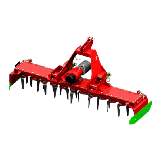
NG-M 101 Power harrow 2,50 - 3,00 m
Address:
Kverneland Group Modena S.p.A.
Strada Ponte Alto 74
41123 MODENA
Italy
Receiver:
Technical Service
Details:
Technical machine information, adjustments and failure finding
Serial number:
> serial number MAPOHxx104265
NG-M 101 Power harrow
1
1
Advertisement
Table of Contents
Troubleshooting

Subscribe to Our Youtube Channel
Related Manuals for Kverneland NG-M 101


Summary of Contents for Kverneland NG-M 101
- Page 1 Technical Service Manual NG-M 101 Power harrow Date: 02-07-2014 Machine type: NG-M 101 Power harrow 2,50 - 3,00 m Address: Kverneland Group Modena S.p.A. Strada Ponte Alto 74 41123 MODENA Italy Receiver: Technical Service Details: Technical machine information, adjustments and failure finding Serial number: >...
- Page 2 CAUTION MESSAGE IMPORTANT NOTE - This manual is intended to be an HANDBOOK manual only for service purposes - The use and maintenance manuals are primary concerning all the characteristic data. - If a inconsistency in data between service manuals and the use and maintenance MAINTENANCE MANUALS DATA ARE PRIMARY ! manuals is find,...
-
Page 3: Table Of Contents
Content General data and equipment. Maintenance and Troubleshooting (Follow) − General data Checking gearbox oil level − Working features − Standard equipment and glossary Attachment − Optional equipment and glossary Oil and grease characteristics − Working tools Bolt tightening torque tables −... -
Page 4: General Data And Equipment
General data and equipment Model NG-M 251 NG-M 301 Working width (m) 2,50 3,00 Transport width (m) 2,63 3,13 Transport length (m) See page Nr.15 Transport height (m) 1,30 Weight (Kg) 1270 (See note) 1410 (See note) Rotor number Distance between rotors (mm) Tines thickness (mm) Working depth (mm) 0-200... -
Page 5: Working Features
General data and equipment Landmark Orientation (500mm diam. packer roller shown) - Page 6 General data and equipment Landmark Orientation (600mm diam. packer roller shown)
- Page 7 General data and equipment Landmark Orientation (550mm diam. cracker roller shown)
- Page 8 General data and equipment Landmark Orientation (600mm diam. Flexline roller shown)
- Page 9 General data and equipment Landmark Orientation (450mm diam. cage roller shown)
- Page 10 General data and equipment Landmark Orientation (550mm diam. cage roller shown)
- Page 11 General data and equipment Landmark Orientation (600mm diam. Actipack roller shown)
- Page 12 General data and equipment Landmark Orientation (500mm diam. packer roller with MC Drill arms shown)
- Page 13 General data and equipment Landmark Orientation (550mm diam. cracker roller with MC Drill arms shown)
- Page 14 General data and equipment Landmark Orientation (450mm diam. cage roller with front hitch kit shown)
- Page 15 General data and equipment Road transport (500mm diam. packer roller shown) Transport Height: H=500 mm Minimum Transport width: NG-M 251: L=2,63 m NG-M 301: L=3,13 m...
- Page 16 General data and equipment Parking position Fig.Nr Type H (m) D (m) 500 mm Packer roller 1,30 1,56 600 mm Packer roller 1,30 1,73 450 mm Cage roller 1,30 1,53 550 mm Cage roller 1,30 1,61 550 mm Cracker roller 1,30 1,66 600 mm Flexline roller...
- Page 17 General data and equipment Working position : Working position: Lower position. Higher position (500 mm Packer roller shown) Maximum cutting depth 200 mm (500 mm Packer roller shown) Maximum cutting depth: 200 mm...
-
Page 18: Standard Equipment And Glossary
General data and equipment Standard equipment glossary Headstock Upper third point pin Frame (NGM 3,00 m shown) II Category lower CEE front safety linkage bracket guard Side deflector kit... - Page 19 General data and equipment Standard equipment glossary Drive shaft Gearbox guard Standard roller guide Standard Roller Standard 12 mm tines...
- Page 20 General data and equipment Roller position (500 mm Packer roller shown) Type H min (mm) H max (mm) 500 mm Packer roller -27,5 600 mm Packer roller 450 mm Cage roller 244,5 550 mm Cage roller 250,5 550 mm Cracker roller (Kerner) -85,5 600 mm Flexline roller 600 mm Actipack roller...
- Page 21 General data and equipment Typical working position...
-
Page 22: Optional Equipment And Glossary
General data and equipment Optional equipment glossary Track eraticator bar Track eraticator bar Track eraticator bar Shear bolt track Rigid track Spring track eraticator eraticator eraticator... -
Page 23: Working Tools
General data and equipment Optional equipment glossary Standard fixing bolts Quick fit tool Standard 12mm Quick fit standard tine 12mm tine Standard fixing bolts Quick fit tool Carbide insert Quick fit carbide 12mm tine insert 12mm tine... -
Page 24: Rollers
General data and equipment Optional equipment glossary 500mm diameter packer roller Support frame Scraper blade 600mm diameter packer roller Support frame Scraper blade... - Page 25 General data and equipment Optional equipment glossary 550mm diameter cracker roller Support frame Scraper blade 600mm diameter Flexline roller Support frame Scraper blade...
- Page 26 General data and equipment Optional equipment glossary 450mm diameter cage roller Support frame Support frame 550mm diameter cage roller...
- Page 27 General data and equipment Optional equipment glossary 600mm diameter Support frame Scraper blade Actipack roller...
-
Page 28: Mc-Drill Roller Support
General data and equipment Optional equipment glossary MC Drill roller support Upper swing arm Lower swing arm 500mm diameter packer roller 550mm diameter cracker roller... -
Page 29: Levelling Bar
General data and equipment Optional equipment glossary Levelling bar position... - Page 30 General data and equipment Optional equipment glossary Levelling bar position with extension...
- Page 31 General data and equipment Optional equipment glossary Accord seeder assembly support...
- Page 32 General data and equipment Optional equipment glossary Mechanical seeder assembly support...
- Page 33 General data and equipment Optional equipment glossary Hydraulic seeder assembly support...
- Page 34 General data and equipment Optional equipment glossary Front hitch with cage roller assembly...
- Page 35 General data and equipment Optional equipment glossary Standard warning panel kit...
-
Page 36: Getting Started
Getting started Connecting power harrow to tractor Step 1 - Disassembly the lower pins hitch, including the safety pins - Insert the spherical joints , then insert again the lower pins hitch and the safety pins Final Lower Hitch Assembly Safety pin Lower pin hitch... - Page 37 Getting started Connecting power harrow to tractor (rear position) Step 2 - Approach the tractor to the power harrow, while is in parking position , with the lower hitch arms lowered - Lift up the lower hitch arms until are fully engaged on the spherical joints...
- Page 38 Getting started Step 3 Connecting power harrow to tractor - Disassembly the top link pin including the safety pin - Insert the top link bar , then insert again the top link pin and the safety pin. Top Link Upper Pin Safety pin Hitch IMPORTANT NOTE...
-
Page 39: Maintenance And Troubleshooting
Maintenance and Troubleshooting Adjusting the side deflectors - During shipping and road transport the side deflectors are locked in secure position. Side deflector Side deflector shield extension... - Page 40 Maintenance and Troubleshooting Adjusting the side deflectors - To position the side deflectors in the correct working position remove the “R” shape security “R” shape Locking pin pin from the locking pin, then remove the security pin locking pin. “R” shape security pin Locking pin - Lift the side deflector, then insert the locking pin...
-
Page 41: Adjusting Side Deflector Side Extensions
Maintenance and Troubleshooting Adjusting the side deflector shield extension Side deflector shield extension - Following the need requested during work the side deflector shield extensions could be adjusted from 306 mm (Up figure) to 426 mm (Left figure) , with 5 step of 30 mm each. Side deflector shield extension... - Page 42 Maintenance and Troubleshooting Adjusting the side deflectors Carriage bolt Side deflector shield extension Self locking nut - Remove the self locking nuts, then remove the side deflector shield extension. - Assemble side deflector shield extension in the chosen position and tight the self locking nuts.
- Page 43 Maintenance and Troubleshooting Side deflector positions Side deflector Side deflector lower position upper position...
-
Page 44: Replacing Tines
Maintenance and Troubleshooting Replacing tines Quick fit tine Standard fixing tine - Remove the quick fit safety pin, then - Loosen the hexagonal head screws, then remove the quick fit pivot pin. remove the fixing plate. - Replace the tine sliding it sideward. - Replace the tine. -
Page 45: Changing Gearbox Speed
Maintenance and Troubleshooting Changing gearbox speed Changing gearbox speed Step #1 - Open the PTO shaft cover , then loosen - To change the working speed follow the hexagonal head screws. carefully the following instructions. - Remove the screws, the washers and then remove the PTO shaft cover PTO shaft cover Washer... - Page 46 Maintenance and Troubleshooting Changing gearbox speed Step #3 Changing gearbox speed Step #2 - Remove the hexagonal head screws and then remove - Remove the circlips and then replace the the gearbox cover and the gearbox gasket. gears following the table on page 46 - Be very careful during gasket dis-assembly and re assembly Output gear...
- Page 47 Maintenance and Troubleshooting Changing gearbox speed Changing gearbox speed Attachment #1: Gear ratio Attachment #2: Info & cautions - Wait until all the moving parts are completely stopped. Working speed - Raise the power harrow and then tilt it forward Model Input gear Output gear...
-
Page 48: Changing Tine Carrier
Maintenance and Troubleshooting Changing tine carrier Headstock - To change tine carrier , follow the hereby instruction carefully. Trough Gearbox Tine carrier... - Page 49 Maintenance and Troubleshooting Changing tine carrier Step #1 Changing tine carrier Step #2 - Loosen the self locking nuts. - Remove the hexagonal head screws and the washers - Lift up the headstock Hexagonal head Washer screw Headstock Self locking nut...
- Page 50 Maintenance and Troubleshooting Changing tine carrier Step #3 Changing tine carrier Step #4 - Loosen the self locking nuts fixing the front and the rear - Loosen and remove the side hexagonal side of gearbox head screws - Remove the hexagonal head screws and the washers Hexagonal head Hexagonal head screw...
- Page 51 Maintenance and Troubleshooting Changing tine carrier Step #5 Changing tine carrier Step #6 Hexagonal head - Remove the gearbox screw - Loosen all the self locking nuts, then Gearbox remove the screws and the washers Use threadlocker - Then loosen the six side hexagonal head LOCTITE Type 243 screws Hexagonal head...
- Page 52 Maintenance and Troubleshooting Changing tine carrier Step #7 Changing tine carrier Step #8 - Remove the trough cover - Loosen the upper nut, then remove the - Then remove the transmission shaft gear Upper nut Trough cover Transmission shaft Gear Use threadlocker LOCTITE Type 243...
- Page 53 Maintenance and Troubleshooting Changing tine carrier Step #9 Changing tine carrier Step #10 - Loosen the cylindrical head socket drive screws - Remove the tine carrier and the tine shaft from the trough Liquid gasket Trough Tine carrier Use A+P Permabond A136 Tine carrier Cylindrical head...
- Page 54 Maintenance and Troubleshooting Changing tine carrier Step #11 Taper roller bearing Tine carrier support 30208 IMPORTANT NOTE: During the tine carrier disassembly and re-assembly ALWAYS use proper tools to avoid damages to shaft seals and taper roller bearings. ALWAYS keep the parts clean and lightly greased.
- Page 55 Maintenance and Troubleshooting Tine carrier glossary Trough Upper nut Gear Taper roller bearing 30208 Taper roller bearing 30209 Spacer Shaft seal Tine carrier support Tine shaft...
-
Page 56: Checking Gearbox Oil Level
Maintenance and Troubleshooting Checking trough grease level Checking gearbox oil level - The machine must be in horizontal position - The machine must be in horizontal position before before checking the transmission grease checking the oil level. level. - Remove the level oil plug , the oil level must match the - Remove the filler cap. -
Page 57: Oil And Grease Characteristics
Getting started Gearbox Oil Characteristic Grade ISO VG 460 Description EP Gear Oil Specifications ANSI/AGMA 9005-94 Approvals DIN 51517 Part 3 - CLP Homologations ISO-L-CKD Applications Gearbox IMPORTANT NOTE - Do not mix Oils of different types and specifications : this could cause malfuncitons and serious damages to items General Grease Type Grade... -
Page 58: Attachment
Attachment #2 Bolts tightening torque tables ISO table coarse thread bolts Max. Pre-stress torque Max. tightening torque (kgm) Bolt class 10.9 12.9 10.9 12.9 Nominal bolt diam. 1270 1520 0,58 1,03 1,46 1,75 1640 2310 2770 1,39 2,48 3,49 4,19 1480 2600 3660... - Page 59 Attachment #2 Bolts tightening torque tables ISO table fine thread bolts Max. Pre-stress torque Max. tightening torque (kgm) Bolt class 10.9 12.9 10.9 12.9 Nominal bolt diam. 1750 2470 2960 1,48 M8x1 1540 2740 3860 4630 M10x1,25 2420 4140 5800 6980 12,8 15,4...
Need help?
Do you have a question about the NG-M 101 and is the answer not in the manual?
Questions and answers
How I can to timing the tines after the repair because I don't marked the tines.
To time the tines on a Kverneland NG-M 101 after repair without markings, follow these steps:
1. Lift the Machine – Use suitable equipment to secure the machine against accidental lowering or dropping.
2. Switch Off the Tractor – Ensure the tractor is switched off and secured against rolling away.
3. Align the Tines – Install the left and right tines according to their prescribed direction of movement to prevent increased wear or machine damage.
4. Secure the Tines – Insert new tines and fasten them with bolts or pins as required.
5. Check Rotation – Manually rotate the tine carrier to ensure proper alignment and movement without interference.
6. Final Inspection – Verify that all fasteners are secured and that the tines are correctly positioned for efficient operation.
This ensures proper functioning and prevents premature wear or damage.
This answer is automatically generated