Advertisement
Quick Links
Technical Service Manual
Date:
Machine type:
Address:
Receiver:
Details:
Serial number:
Power Harrow H series 3 - 4m
01.01.2017
Power Harrow H series 3-4m
Kverneland Group Soest GmbH.
Coesterweg 42
59494 Soest
Germany
Technical Service
Technical machine information, adjustments and failure finding
> serial number ACPOHxx........
1
1
Advertisement

Subscribe to Our Youtube Channel
Related Manuals for Kverneland H Series


Summary of Contents for Kverneland H Series
- Page 1 Technical Service Manual Power Harrow H series 3 - 4m Date: 01.01.2017 Machine type: Power Harrow H series 3-4m Address: Kverneland Group Soest GmbH. Coesterweg 42 59494 Soest Germany Receiver: Technical Service Details: Technical machine information, adjustments and failure finding Serial number: >...
- Page 2 Content General data and equipment……......3 Circuit with Control panel……………………………42 − − Road transport Central gearbox − − Working position Side gearbox − − Construction Drivelines − Rollers options − Leveling bar regulation Gearboxes …………………………………….……..17 − Central gearbox disassembly − Central gearbox assembly −...
- Page 3 NG-S 101 – General data and equipment Specifications NG-S 401 NG-S 451 NG-S 501 NG-S 601 2,90 m Transport width 1,65 m Transport length with roller 1,73 m Working length with roller 1,5 m Working hight 2,11 m 2,35 m 2,6 m 3,1 m Transport hight...
- Page 4 General data and equipment Road transport 1650 mm 2900 mm • Total weight : 3,900 kg • Rear view...
- Page 5 General data and equipment Road transport 1650 mm • Total weight : 3,900 kg...
- Page 6 General data and equipment Road transport 2900 mm • Rear view • Front view...
- Page 7 General data and equipment Working position • Total weight : 3,900 kg...
- Page 8 General data and equipment Working position • Front view 6000 mm • Rear view...
- Page 9 General data and equipment Working position 700 mm 1730 mm • Total weight : 3,900 kg...
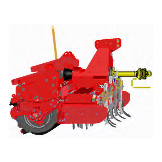
- Page 10 General data and equipment Construction hydraulic distributors hooks for locking the machine into closed position third-point attachment Oil cooler Lightning equipment rear drive shaft hook jacks for machine closing hydraulic roller adjustment Leveling bar Cat.III - IV floating lower attachments Central gearbox with lever control Front drive shaft guard Track eradicator...
- Page 11 General data and equipment Construction MA44000106 Ring Nut • Assembled with Loctite 243 BOLT : Tighten it to 175 Nm • Tighten it to 140-160 Nm • Dent the top neck of the metal ring-nut on two points Trough 10mm Seal with silicon special profile rubber Angst-...
- Page 12 General data and equipment Construction Resetting operation of tine carriers’ ” TIMING”, -30° -45 -60 -15 60° 45° 30° 75° 0° -75° Timing process: 1. Remove all tine carriers. 2. Assemble one central tine carrier and rotate it so that the tines are in-line with the axis of the trough (reference rotor).
- Page 13 General data and equipment Construction Att.on!! We advice do not mix up The Synthetic grease with Mineral grease Quantity Grease type Grease Brand (liter) suggested features Lenght for each trough LITHIUM grease EP AGIP- GREASE EP 00 NLGI 00 G00K SHELL ALVANIA EP-LF DIN 51826 16,5...
- Page 14 General data and equipment Construction...
- Page 15 General data and equipment Construction IMPORTANT: 1° During the replacement of new central gearbox, please take care about lateral drive line Attached you will find some info about, how to respect the phase on the lateral shafts during maintenance work. 2°...
- Page 16 General data and equipment Rollers Simplified Normal cultivation conditions condition techniques Packer Roller Diam 600 Sandy Flexline Cage roller roller Medium Packer Roller Diam 600 or Tough Diam 500 Cracker roller Heavy Actipack roller...
- Page 17 General data and equipment Leveling bar equipment...
- Page 18 Central gearbox 3 speed (Comer D-825 A) MAGE59……………………… • - Disassembly …………………. • - Assembly ……………………. • - Technical specifications …… NOTES • Warning : Disassembled shims if not damaged, must to be assembled in the same positions.
- Page 19 1. Greabox Disassembly • Tools : Chisel, hammer, fork wrench n°17 • Tools : Allen screw wrench n°9/16”, Allen screw wrench n°4, snap ring pliers Fork wrench n°1/2”-17-22-27-30, Extractor, adjustable wrench Adjustable wrench, snap ring pliers. • Plugs (32),(39),(47) and empty the oil •...
- Page 20 2. Disassembly • Tools : • Tools : Chisel, hammer, snap ring pliers, Extractor, snap ring pliers, chisel, hammer. Extractor, fork wrench n°17, adjustable wrench • Disassemble oil seals (4),(30) • Disassemble shaft (19), inner ring (12) snap ring (8) and take away shim (13) •...
- Page 21 1. Assembly • Tools : Pipe, hammer, snap ring pliers, Torquemeter, adjustable wrench, chisel. • Assemble outer ring (5) inside the housing • Insert the inner ring (5). • Assemble inside housing: Spacer (65), gear(31), spacer(20),gear (17),spacer(16), shim (1),gear (7) •...
- Page 22 2. Assembly • Tools : • Tools : Chisel, hammer, snap ring pliers, Fork wrench n°17, hammer, torquemeter, Torquemeter, adjustable wrench, Snap ring pliers, comparator, adjustable wrench, Fork wrench n°17, dynamometric wrench Dynamometric wrench, chisel • Assemble gears(14),(21) bearing brass(15), •...
- Page 23 3. Assembly • Tools : Fork wrench n°1/2”-17-22-27, dynamometric wrench, Pipe, hammer, allen screw wrench n°4-9/16”, manometer. ASSEMBLY AND MAINTANANCE • Put Silicone between housing and cover • Assemble pre-mounted cover (57), bolts (10) and • The contact of crown wheel and pinion must be located in Fig. A tighten to 7÷9 kgm.
- Page 24 3. Technical specifications Backlash control Lubrication The figure shown how check the backlash - Gearbox operates with oil lubrication - The type of oil recommended is : SAE 90EP - Oil Quantity 7 Litres Oil change : - First oil change is recommended after the first 50 hours of work other change after 600 hours and / or once per year at least.
- Page 25 Laterl gearbox MAGE60 ……………………… • - Disassembly …………………. • - Assembly ……………………. • - Technical specifications …… NOTES • Warning : Disassembled shims if not damaged, must to be assembled in the same positions.
- Page 26 1. Disassembly • Tools : • Tools : Fork wrench n°13-17-19, chisel, hammer Snap ring pliers, pipe, hammer, extractor, chisel • Unscrew plus (10),(29) and empty the oil • Disassemble snap ring (18), • Unscrew bolts (12), copper washer (24). cover (21) o-ring (13) oil seal (19) from cover (21) •...
- Page 27 1. Disassembly • Tools : Fork wrench n°17, pipe, chisel, hammer, extractor. • Unscrew bolts (12) and take away cover (26) • Disassemble outer ring (3),take away shim (2) • Hit the pinion shaft from side (B) extract from housing. •...
- Page 28 1. Assembly • Tools : • Tools : Pipe, hammer, fork wrench n°17, Pipe, hammer, snap ring pliers, Dynamometric wrench, torquemeter Torquemeter, chisel. • Assemble outer ring using pipe and hammer NOTES • Clean all the components from remaining grease and silicone. •...
- Page 29 2. Assembly • Tools : Fork wrench n°13-17-19, comparator, Dynamometric wrench, pipe, hammer • Test the right mesh between gears, use (Prussian blue) on the gear’s teething. • Assemble pre-mounted flange (16), bolts (28) • Assemble shim (14) outer ring (15),(20) •...
- Page 30 4. Technical specifications ASSEMBLY AND MAINTANANCE Backlash control A) The contact of crown wheel and pinion must be located like in Fig. A The figure shown how check the backlash ( mark obtained without load on crown wheel and pinion ) Use the shims in order to obtain the right contact.
- Page 31 4. Technical specifications...
- Page 32 Basic hydraulic circuit (std. equipment): schematics hydraulic...
- Page 33 Basic hydraulic circuit (std. equipment): Distributor block...
- Page 34 Basic hydraulic circuit (std. equipment): Roller sequence circuit...
- Page 35 Basic hydraulic circuit (std. equipment): Folding circuit...
- Page 36 Basic hydraulic circuit (std. equipment): Transport lock circuit...
- Page 37 Basic hydraulic circuit (std. equipment): Roller lift circuit...
- Page 38 Basic hydraulic circuit (std. equipment): Line markers circuit (optional)
- Page 39 Hydraulic circuit + electro-hydraulic controls : schematics hydraulic...
- Page 40 Hydraulic circuit + electro-hydraulic controls : Connections and functions...
- Page 41 Hydraulic circuit + electro-hydraulic controls : Folding-transport lock circuit...
- Page 42 Hydraulic circuit + electro-hydraulic controls : Roller lift circuit...
- Page 43 Hydraulic circuit + Control panel : schematics hydraulic...
- Page 44 Hydraulic circuit + Control panel : Junction Box + Control box...
- Page 45 Hydraulic circuit + Control panel : Interface on coulter bar brackets...
- Page 46 Hydraulic circuit + Control panel : Line marker function...
- Page 47 Hydraulic circuit + Control panel : Pre-emergence marker function...
- Page 48 Hydraulic circuit + Control panel : Coulter bar lift...
- Page 49 Hydraulic circuit + Control panel : Coulter bar pressure...
- Page 50 Hydraulic circuit + Control panel : Pre-emergence marker function...
- Page 51 Hydraulics – fittings ¼ turn Assembly of fittings: Leakage If you tighten the thread with to high torque you will elongate the - Fit the connecting nut onto the - Tighten the nut with the - If hydraulic connections are threats and the fittings starts tread of the fitting and tighten it required spanner by ¼...
- Page 52 Requests...
Need help?
Do you have a question about the H Series and is the answer not in the manual?
Questions and answers