Table of Contents
Advertisement
Vario 1
Vario 2
Linearantrieb / Linear actuator / Vérin électrique /
Motore lineare / Motor lineal
DE
EN
FR
IT
ES
Montageanleitung
Bitte bewahren Sie die Montageanleitung auf!
Operating instructions
Please take care of the operating instructions!
Instructions de montage
Veuillez conserver les présentes instructions de montage!
Istruzioni per l'uso
La preghiamo di conservare le istrzioni per l'uso!
Instrucciones de montaje
Por favor, conserve estas instrucciones de montaje!
Stand 04/2016, TN: 2010854
Advertisement
Table of Contents

Related Manuals for elero Vario 2


Summary of Contents for elero Vario 2
- Page 1 Vario 1 Vario 2 Linearantrieb / Linear actuator / Vérin électrique / Motore lineare / Motor lineal Montageanleitung Bitte bewahren Sie die Montageanleitung auf! Operating instructions Please take care of the operating instructions! Instructions de montage Veuillez conserver les présentes instructions de montage! Istruzioni per l‘uso...
- Page 2 Die deutsche Montageanleitung ist die Originalfassung. Alle anderssprachigen Dokumente stellen Übersetzungen der Originalfassung dar. Änderungen vorbehalten. Alle Rechte für den Fall der Patent-, Gebrauchs- muster- oder Geschmacksmustereintragung vorbehalten. Translation from the original German version. All other documents in different languages are translations of the original version.
-
Page 3: Table Of Contents
Table of contents Table of contents General ....................3 Information relating to the installation instructions ........... 3 Standards and guidelines ................. 3 Intended use ..................... 3 Foreseeable misuse ..................4 Warranty and liability ..................4 Customer service of the manufacturer ............. 5 Safety .................... - Page 4 Table of contents Setting the electronic limit switches ..............20 4.4.1 Teach-in of the limit positions ................. 21 4.4.2 Displays in the event of errors ................ 23 Dimensions sheet ................... 23 Declaration of incorporation ............24 Waste disposal ................. 25 Scrapping .......................
-
Page 5: General
General General Information relating to the installation instructions The classification of the contents is based on the life stages of the linear drive (here- inafter referred to as the “device”). The manufacturer reserves the right to make changes to the technical specifications stated in these installation instructions. In detail these can differ from the respective version of the device without the factual information being fundamentally changed and without losing their validity. The cur- rent status of the technical specifications can be requested from the manufacturer at any time. -
Page 6: Foreseeable Misuse
General The device must be operated only by trained and authorized skilled personnel subject to compliance with all safety notices and directions. Safe and error-free use and operating safety of the device can only be guar- anteed subject to use in compliance the intended use in accordance with the specifications set out in these installation instructions. -
Page 7: Customer Service Of The Manufacturer
General Customer service of the manufacturer The device may be repaired only by the manufacturer in the event of a fault. The address for sending in the device to the customer service department can be found on the inside of the back cover. Mechanically secure the machine before dismantling the device. -
Page 8: Safety
Safety Safety General safety notices and directions These installation instructions contain all the safety notices and directions that must be observed in order to avoid and prevent dangers when working with the device in the individual life cycles. Safe use of the device is guaranteed when all the specified safety notices and directions are complied with. - Page 9 Safety The following table describes the symbols used in these installation instructions for the graphic display of danger situations in connection with the symbol for the danger level. Symbol Meaning Danger due to an electrical voltage, electric shock: This symbol refers to dangers associated with electrical currents.
-
Page 10: Safety Principles
Safety Safety principles The device is built according to state-of-the-art technology and the generally accepted rules of safety and it is safe to operate. The basic safety and health requirements of the applicable laws, standards, directives and guidelines have been applied in the construction of the device. The safety of the device is con- firmed by the Declaration of Incorporation. -
Page 11: General Duties Of The Plant Operator
Safety General duties of the plant operator The plant operator is obligated to use the device only in perfect and opera- ❏ tionally safe condition. He must ensure that, in addition to the safety notices and directions in the installation instructions, the generally accepted safety and accident prevention regulations, the specifications of DIN VDE 0100 and the provisions relating to environmental protection of the respective country of use, are heeded and complied with. -
Page 12: Safety Notices And Directions Relating To The Technical Condition
Safety Safety notices and directions relating to the technical condi- tion The device must be checked before installation for damage and proper ❏ condition. The plant operator is obligated to operate the device only in perfect and ❏ operationally safe condition. The technical condition must comply with the legal requirements at all times. -
Page 13: Safety Instructions Relating To Operation
Safety Safety instructions relating to operation The operator of the device is obligated to ensure the safe and proper state ❏ of the device before the initial start of operation. This is also necessary during operation of the device at regular intervals to ❏... -
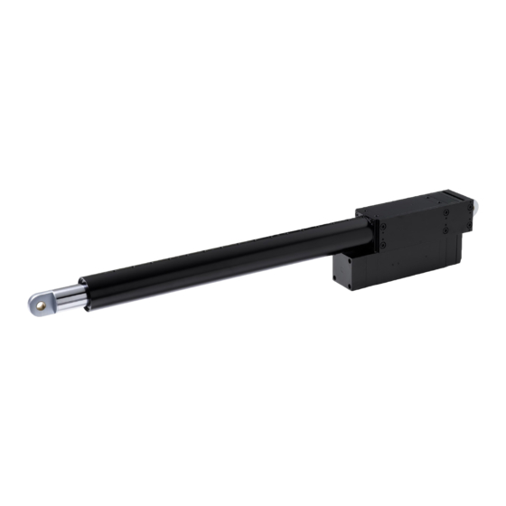
Page 14: Product Description
Product description Product description General The device is an electromechanical linear drive. It performs linear movements. Abb. 1 Components of the device Housing Fastening on piston side Connections for the connecting cable Sensor for the electronic limit switch Fastening on housing side Product variants The device can be obtained in various configurations. -
Page 15: Technical Specifications
Technical specifications All information in this section relates to an ambient temperature of 20°C. 3.3.1 Summary of the technical parameters Technical specifications Vario 1 Vario 2 Rated voltage 400 V 3 AC, 50 Hz Control power supply 24 V DC... -
Page 16: Information Relating To The Self-Locking Facility
Product description 3.3.2 Information relating to the self-locking facility WARNING Danger of injury through loss of the self-locking facility. Crushing and fatal injuries are possible. • Use device with a brake. CAUTION Possible damage to the device or customer’s machine through loss of the self- locking facility. -
Page 17: Installation
Installation Installation WARNING Danger of injury due to weathering influences. The skin may suffer frostbite or burns. • Wear personal protective equipment. WARNING Danger of injury due to incorrectly dimensioned mountings. Crushing and fatal injuries are possible. • Use only fastening materials that are suitable for the dimensions of the mountings. -
Page 18: Mechanical Fastening
Installation CAUTION Damage to the device due to the connecting rod jamming. • The linear path of the piston must be freely moveable at all times. • The pivoting range of the device must be kept free. CAUTION Damage to the device due to loss of the support and holding function. • Pay attention to static loads. -
Page 19: Electrical Connection
Installation If designed with a pivot pin (optional) or with threaded holes (optional) the fas- tening on the housing side is replaced. Electrical connection WARNING Danger of life-threatening injury due to faulty electrical connection. Electric shock possible. • Check the proper connection of the PE conductor prior to initial start of ope- ration. -
Page 20: Optional Attachments
Installation Optional attachments 4.3.1 Optional brake CAUTION Damage to the device due to incorrect connection of the brake. • Operate the device only when the brake is released. • Do not tap the brake voltage parallel to the motor. With the integrated brake you can decelerate the stroke movement of the con- necting rod faster and optimize the static safety. -
Page 21: Optional Analog Output (0 - 10 V)
Installation Electrical parameters Signal level low max. 0.5 V Rise time t max. 1 µs Fall time t max. 1 µs Short-circuit resistant outputs CE conformity in compliance with EN 50081-2 and EN 55011 class B Tab. 2 Electrical parameters of the shaft encoder Signal A ¯... -
Page 22: Optional Programmable Intermediate Position
Installation 4.3.4 Optional programmable intermediate position Teach-in of the intermediate position is not possible until both limit positions have been taught in. The red button is used to teach in the intermediate position. Traverse the drive to the desired intermediate position. Hold down the red button for at least 3 s. -
Page 23: Teach-In Of The Limit Positions
Installation The adjusting buttons are located on the side of the housing and are covered by dummy screw unions (see Fig. 1 “Components of a device”). Before the programming or adjustment of the limit positions you must remove the dummy screw unions with a standard screwdriver. - Page 24 Installation Teach-in of the limit position “Extended” (red button): Traverse the drive to the desired position. Save the position by briefly pressing the red button. The red button lights up. The limit position “Extended” is taught in. The red button goes out, when the piston is moved away from the limit posi- tion.
-
Page 25: Displays In The Event Of Errors
Installation 4.4.2 Displays in the event of errors The error situations described below are signalled by the flashing of the red and green buttons. If the display is flashing, the device can no longer traverse for safety reasons. Green button flashing fast (> 3 Hz): • The drive has overrun a limit position and has stopped on the safety limit switch. • Under normal operating conditions the drive cannot be traversed again to an operational position. -
Page 26: Declaration Of Incorporation
Declaration of incorporation Declaration of incorporation The complete declaration of incorporation can be downloaded from our website: www.elero-linear.de/downloads. -
Page 27: Waste Disposal
Waste disposal Waste disposal Scrapping When scrapping the device, comply with the internationally, nationally and re- gionally specific laws and regulations valid at that point in time. Ensure that the recycling capability, dismantling capability and separation capa- bility of the materials and subassemblies as well as the environmental and health dangers are all taken into consideration for the recycling and waste dis- posal. - Page 28 GmbH Linearantriebstechnik Naßäckerstraße 11 07381 Pößneck Deutschland +49 3647 46 07-0 +49 3647 46 07-42 info@elero-linear.de www.elero-linear.com...
Need help?
Do you have a question about the Vario 2 and is the answer not in the manual?
Questions and answers