
Related Manuals for nvent RAYCHEM Elexant 4020i


Summarization of Contents
1. OVERVIEW
1.1 Introduction
General introduction to the manual's content.
1.2 Vital Information
Important information for setup and operation.
1.3 Technical Support
Contact information for customer support.
2. INSTALLATION AND WIRING
2.1 Initial Inspection
Procedure for checking the shipping container for damage.
2.2 Operator Safety Considerations
Safety information for handling the controllers.
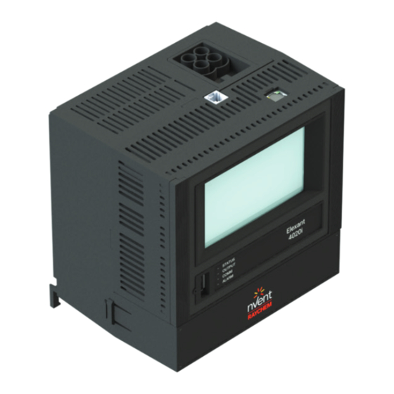
2.3 Elexant 4010i/4020i Assembly
Displays physical assemblies of the units.
2.4 Connection and Indicators
Identifies various connections and indicators on the unit.
2.5 Mounting/Removal Procedures
Instructions for mounting and removing the controller.
2.6 Wiring and Interfaces
Details on connecting power, loads, and interfaces.
3. PRODUCT OPERATIONS
3.1 Control Features
Describes control features and parameters.
3.2 Monitoring
Details configuration and measured temperatures.
3.3 Communication
Details Modbus RTU and Modbus/TCP protocols.
3.4 Device Information
Lists key identifying information for the controller.
3.5 Alarms
Explains basic alarm configuration options and sources.
3.6 Profiles
How to load and save configuration profiles.
3.7 Internal Memory
Information on internal memory storage.
3.8 Graphical User Interface (GUI)
Interaction via touch screen interface.
3.9 LED Status Indicators
Explains the meaning of front panel LEDs.
3.10 GUI Screen Saver Mode
Feature that turns off the screen after inactivity.
4. SAFETY LIMITER
4.1 Safety Limiter
Overview of the safety limiter function and its capabilities.
4.1.4 Resetting the Safety Limiter
Procedures for resetting the safety limiter after a trip.
4.1.5 Setting the Temperature Set Point
How to configure the safety limiter temperature set point.
4.1.6 Main Output Interlock
How the safety limiter affects the main output.
4.1.8 Functional Test
Procedure for testing the safety limiter functionality.
5. GRAPHICAL USER INTERFACE
5.1 Home Screen
Main menu of the user interface.
5.2 Main Screen
Displays current status and key readings.
5.2.4 Main Screen: Three-phase Controller
Main screen display for 3-phase variants.
5.3 Information Screen
Displays unit model, firmware, and serial number.
5.4 Control Setup
Configuration page for temperature, mode, and output.
5.5 Control Mode Page
Settings for control algorithm and output switch.
5.6 Output Limiting Page
Parameters for limiting output power, current, or duty cycle.
5.7 Temperature Settings Page
Settings for temperature sensors and limiting.
5.8 Electrical Settings
Monitors and alarms for trace current, ground fault, voltage, resistance.
5.9 Alarms
Displays current active alarms and allows reset.
5.10 Maintenance Page
View and reset min/max recorded values.
5.11 Profiles Page
Load and save configuration profiles via USB.
5.12 Network Setup Page
Configure Modbus, Ethernet, or Profibus network settings.
5.13 Safety Limiter Settings Page
Configure Safety Limiter settings.
5.14 User Interface Settings
Configure passcode, language, and units.
6. FIRMWARE UPGRADE
6.1 Firmware Upgrade Procedure
Steps to upgrade the controller firmware.
7. TROUBLESHOOTING
7.1 Troubleshooting
Common indications, causes, and corrective actions.
8. APPENDIX A
8.1 List of Abbreviations
Definitions of common abbreviations used.
8.2 Profiles - Default Settings
Default configuration settings for profiles.
Need help?
Do you have a question about the RAYCHEM Elexant 4020i and is the answer not in the manual?
Questions and answers