Sign In
Upload
Download
Table of Contents
Contents
Add to my manuals
Delete from my manuals
Share
URL of this page:
HTML Link:
Bookmark this page
Add
Manual will be automatically added to "My Manuals"
Print this page
×
Bookmark added
×
Added to my manuals
Manuals
Brands
Polon-Alfa Manuals
Security System
4500
Operation and maintenance documentation
Polon-Alfa 4500 Operation And Maintenance Documentation
Interactive fire detection and alarm system, automatic fire extinguishing addressable control panel
Hide thumbs
1
2
3
Table Of Contents
4
5
6
7
8
9
10
11
12
13
14
15
16
17
18
19
20
21
22
23
24
25
26
27
28
29
30
31
32
33
34
35
36
37
38
39
40
41
42
43
44
45
46
47
48
49
50
51
52
53
54
55
56
57
58
59
60
61
62
63
64
65
66
67
68
69
70
71
72
73
74
75
76
77
78
79
80
81
82
83
84
85
86
87
88
89
90
91
92
93
94
95
96
97
98
99
100
101
102
103
104
105
106
107
108
109
110
111
112
113
114
115
116
117
118
119
120
121
122
123
124
125
126
127
128
129
page
of
129
Go
/
129
Contents
Table of Contents
Bookmarks
Table of Contents
Table of Contents
1 Introduction
Documentation Contents
Control Panel Application
Safety Conditions
Electric Shock Protection
Installation and Equipment Safety
Repairs and Maintenance
Fuse Replacement
Definitions
2 Device Completeness
3 Technical Specifications
4 Design Descriptions
Control Panel Overall Description
Modules Arrangement
Handling and Signalling Elements
Introduction
Detection Unit Handling and Signalling Elements
Extinguishing Unit LED Optical Signalling Devices
Numerical Keypad and Edition Push Buttons
5 Operation Description
General Description
Tso-4500 Operator Panel
Central Controller Module
Module Signalling and Handling Elements
Msl-1M Line Module
Programmable Outputs/Inputs Module
General Description
PK Relay Outputs and LS Signal Outputs
Fire Alarm Devices Output (TYPE 1)
Fire Alarm Transmission Devices Output (TYPE 2)
Protecting Devices Output (TYPE 3)
Fault/Technical Alarm Signalling Output (TYPE 4)
Information Output (TYPE 5)
Reset Output (TYPE 6)
LK Monitoring Input
Interface Module
PORT 1, PORT 2, PORT 3 Communication Ports
Output to TSR-4000 Terminal
Printer
Power Supply Module
Control Panel Operation with Battery Cluster
6 Addressable Detection Lines
Detection Line Types
Addressable Elements Numbering
Automatic Configuration
Configuration with Verification
Manual Number Assigning
Design Guidelines
7 Alarming Arrangement
Detection Zone
Addressable Elements Declaration
Assigning Alarming Parameters to Zones
Eks-4001 Monitoring and Controlling Elements Declaration
Ews-4001 Multi-Output Controlling Elements Declaration
Ewk-4001 Multi-Input Monitoring Elements Declaration
Sal-4001 Acoustic Signalling Devices Declaration
Ucs 4000 Universal Controlling Panels Declaration
Ucs 6000 Universal Control Panels Declaration
Tsr-4000 Terminals Declaration
8 Functionality Description
Alarming
Alarm Types
One-Stage Alarm (Variant #1)
Two-Stage Alarm (Variant #2)
One-Stage Alarm with Single Reset (40/60 Sec.) of a Fire Warning Device (Variant #3)
One-Stage Alarm with Single Reset (60 Sec./8 Min.) of a Fire Warning Device (Variant #4)
Two-Stage Alarming with Single Reset (40/60 Sec.) of a Fire Warning Device (Variant #5)
Two-Stage Alarm with Single Reset (60 Sec./8 Min.) (Variant #6)
One-Stage Alarm with a Coincidence Including Two Fire Warning Devices (Variant #7)
Two-Stage Alarm with a Coincidence Including Two Fire Warning Devices (Variant #8)
Interactive One-Stage Alarm (Variant #9)
Interactive Two-Stage Alarm (Variant #10)
One-Stage Alarm with a Group-Time Coincidence (Variant #11)
Two-Stage Alarm with a Group-Time Coincidence (Variant #12)
Two-Stage Alarm with a Group-Time Coincidence to Accelerate a 2
Nd Stage Alarm (Variant #13)
Two-Stage Alarm with Initial Zone Reset and a Group Coincidence to Accelerate a
Alarm (Variant #14)
Nd Stage
Two-Stage Alarm with a Coincidence Including Two Fire Warning Devices to Accelerate a
Stage Alarm (Variant #15)
Two-Stage Alarm with Initial Zone RESET and a Coincidence Including Two Fire Warning Devices to Accelerate a
Nd Stage Alarm (Variant #16)
One-Stage Alarm with Temporary Zone Dis-Actuation (Variant #17)
Alarm with a Manual Call Point (ROP)
Alarming in the "DELAYS OFF" Mode
Alarming in the "PERSONNEL ABSENT" Mode
Faults Signalling
Fault Types
Testing
TSO-4500 Board Signalling Elements Testing
Testing Fire Line Elements in Zone
EWS-4001 Controlling Elements Testing
EWK-4001 Monitoring Elements Testing
SAL-4001 Acoustic Signalling Devices Testing
Line Elements Location
Modules Testing
System Elements Disablement/Re-Enablement
Fire Warning Devices and Zones Disablement/Re-Enablement
PK Relays Disablement/Re-Enablement
LS Signalling Lines Disablement/Re-Enablement
LK Monitoring Lines Disablement/Re-Enablement
EKS-4001 Monitoring and Controlling Elements Disablement/Re-Enablement
EWS-4001 Controlling Elements Disablement/Re-Enablement
EWK-4001 Monitoring Elements Disablement/Re-Enablement
SAL-4001 Acoustic Signalling Devices Disablement/Re-Enablement
Modules Disablement
Event and Alarm Memory
Event Memory
Alarm Memory
9 Fire Extinguishing Control Module
General Description
Operation Modes
Fire Extinguishing Actuation Mode (EXTINGUISHING START)
Discharge Mode (DISCHARGE)
Technical Alarm Mode
Fault Mode (FAULT)
Blockade Mode (BLOCKADE)
EXTINGUISHING START Blockade
DISCHARGE Blocking
Testing Mode
Monitoring Lines and Their Functions
Fk1 EXTINGUISHING START Function
Fk2 RESERVE START Function
Fk3 EXTINGUISHING STOP Function
Fk4 EXTINGUISHING BLOCKADE Function
Fk5 MANUAL CONTROL Function
Fk6 FIRE EXTINGUISHING AGENT OUTFLOW MONITORING Function
Fk7 FIRE EXTINGUISHING AGENT PRESSURE/MASS MONITORING Function
Fk8 EXTERNAL ALARM INPUT Function
Fk9 NON-ELECTRICAL BLOCKADE Monitoring Function
Fk10 FIRE EXTINGUISHING AGENT OUTFLOW END Function
Fk11 UNIVERSAL MONITORING INPUT Function
Relay Outputs
Relay Outputs General Description
Relay Outputs Functions General Description
10 Control Panel Network Operation
Network Module
Network Panel Functionality
Local Mode
Collective Mode
Remote Mode
11 Standard Configuration
User Configuration Programming
Standard Configuration/Access Codes Loading
12 Access Codes
13 Installation
Control Panels Installation Location
Power Supply Connection
Line Elements Installation
Control Panel Inputs and Outputs
14 Operation and Maintenance
Proper Usage Regulations
Periodical Inspections and Maintenance Guidelines
15 Packaging, Transportation and Storage
Packaging
Transport Guidelines
Storage Guidelines
16 Designer's Tables - Detection Unit
17 Designer's Tables - Extinguishing Unit
Advertisement
Quick Links
Download this manual
See also:
Operation and Maintenance
POLON 4000
INTERACTIVE FIRE DETECTION AND ALARM SYSTEM
POLON 4500
AUTOMATIC FIRE EXTINGUISHING
ADDRESSABLE CONTROL PANEL
Operation and Maintenance Documentation
ID-E316-001GB
IIIC Edition
Table of
Contents
Previous
Page
Next
Page
1
2
3
4
5
Advertisement
Table of Contents
Need help?
Do you have a question about the 4500 and is the answer not in the manual?
Ask a question
Questions and answers
Related Manuals for Polon-Alfa 4500
Security System Polon-Alfa 4000 Operation And Maintenance Documentation
Interactive fire detection and alarm system, automatic fire extinguishing addressable control panel (129 pages)
Security System Polon-Alfa 4000 Installation And Maintenance Manual
Interactive fire detection and alarm system (11 pages)
Security System Polon-Alfa POLON 4000 Series Installation And Maintenance Manual
Interactive fire detection and alarm system. fire manual call points (10 pages)
Security System Polon-Alfa POLON 4000 Installation And Maintenance Manual
Interactive fire alarm system wireless manual fire call points (18 pages)
Security System Polon-Alfa POLON 4000 Installation And Maintenance Manual
Interactive fire detection and alarm system, microprocessor addressable multi-input supervising device (8 pages)
Security System Polon-Alfa POLON 4000 Installation And Maintenance Manual
Interactive fire detection and alarm system, microprocessor addressable multi-output control device (8 pages)
Security System Polon-Alfa POLON ROP-4001M Installation And Maintenance Manual
Interactive fire detection and alarm system. fire manual call points (10 pages)
Security System Polon-Alfa POLON ROP-4001MH Installation And Maintenance Manual
Interactive fire detection and alarm system. fire manual call points (10 pages)
Security System Polon-Alfa ROP-3000 Installation And Maintenance Manual
Manual call points, fire alarm system for polon 3000 (13 pages)
Security System Polon-Alfa SAB-6001 Installation And Maintenance Manual
Addressable acoustic and visual alarm devices (sounder beacon) (22 pages)
Security System Polon-Alfa SAL-4001 Installation And Maintenance Manual
Addressable accoustic signalling device (8 pages)
Security System Polon-Alfa Ignis 1000 Operation And Maintenance Documentation
Fire detection and alarm control panel (45 pages)
Security System Polon-Alfa SG-1 Installation And Maintenance Manual
Alarming devices (12 pages)
Security System Polon-Alfa EKS-6222P Installation And Maintenance Manual
Microprocessor based addressable control and monitoring element (17 pages)
Summarization of Contents
Introduction to POLON 4500 Control Panel
Documentation Contents Overview
Overview of the manual's sections, purpose, and scope.
Control Panel Application
Details the specific applications and functions of the POLON 4500 fire alarm control panel.
Safety Conditions
Details essential safety precautions for the installation, operation, and maintenance of the control panel.
Definitions and Key Terms
Provides definitions for key terms, acronyms, and concepts used within the manual.
Device Completeness
Technical Specifications
Design Descriptions
Control Panel Overall Description
General overview of the POLON 4500 control panel's physical design, components, and primary functions.
Modules Arrangement
Details the internal module arrangement, layout, and connectivity within the control panel.
Operation Description
General Description of Operation
Introduces the POLON 4500 as a modular, multi-processor fire extinguishing control system.
TSO-4500 Operator Panel
Lists the components and functions of the operator interface panel.
PSC-46 Central Controller Module
Details the PSC-46 controller's architecture, microprocessors, redundancy, and communication bus.
MSL-1M Line Module
Explains the function, capabilities, and connectivity of the MSL-1M module for detection lines.
PPW-45 Programmable Outputs/Inputs Module
Describes the PPW-45 module for connecting external devices using its programmable relays and I/O.
MIK-48 Interface Module
Covers the module for connecting external devices via serial and USB ports.
DR-48 Printer
Details the functionality of the integrated thermal printer for event logging.
Power Supply Module
Explains the power supply options, including mains and reserve battery operation.
Control Panel Operation with Battery Cluster
Discusses how the control panel operates with an external battery cluster for backup power.
Addressable Detection Lines
Detection Line Types
Differentiates between loop-shaped and radial configurations for addressable detection lines.
Addressable Elements Numbering
Explains methods for assigning addresses to detection line elements.
Design Guidelines for Detection Lines
Provides recommendations for designing addressable detection line installations.
Alarming Arrangement
Detection Zone Configuration
Explains how addressable elements are grouped into zones for alarming, identification, and configuration.
Addressable Elements Declaration
Details the process for declaring addressable elements, including their data and zone assignments.
Assigning Alarming Parameters to Zones
Describes how to configure alarming variants and user messages for each zone.
EKS-4001 Element Declaration
Covers the declaration and configuration of EKS-4001 elements for monitoring and control.
EWS-4001 Element Declaration
Details the declaration and programming of EWS-4001 elements for controlling multiple outputs.
EWK-4001 Element Declaration
Explains the declaration and configuration of EWK-4001 elements for monitoring multiple inputs.
SAL-4001 Acoustic Signalling Devices Declaration
Describes the declaration and programming of SAL-4001 acoustic signalling devices.
UCS 4000 Universal Controlling Panels Declaration
Covers the declaration and integration of UCS 4000 universal controlling panels.
UCS 6000 Universal Control Panels Declaration
Details the declaration and integration of UCS 6000 universal control panels.
TSR-4000 Terminals Declaration
Explains how to declare TSR-4000 terminals for remote signalling.
Functionality Description
Alarming Functions
Details different alarm types, stages, activation criteria, and their signalling mechanisms.
Faults Signalling
Explains how the control panel detects, signals, and displays various system faults.
System Testing Procedures
Outlines the procedures for testing various system elements and modules.
System Elements Disablement/Re-enablement
Describes how to disable or re-enable system elements like lines, zones, and outputs.
Event and Alarm Memory
Discusses the storage and retrieval of events and alarms in the control panel's memory.
MSG-45 Fire Extinguishing Control Module
General Description of MSG-45 Module
Introduces the MSG-45 module for controlling fire extinguishing devices in zones.
MSG-45 Operation Modes
Details the various operational modes of the MSG-45 module, including EXTINGUISHING START and DISCHARGE.
Monitoring Lines and Their Functions
Explains the functions and programming of the monitoring lines connected to the MSG-45 module.
Control Panel Network Operation
MSI-48 Network Module
Describes the MSI-48 module used for connecting control panels into a network.
Network Panel Functionality
Explains the operational modes (local, collective, remote) for control panels operating within a network.
POLON Configuration
User Configuration Programming
Guides the user on programming the control panel to match the specific installation design requirements.
Standard Configuration and Access Codes Loading
Explains how to load default settings and factory access codes.
Access Codes
Installation
Control Panel Installation Location
Specifies requirements for selecting and preparing the control panel's installation site for optimal visibility and access.
Power Supply Connection
Provides instructions for connecting the mains power supply and the emergency battery power.
Line Elements Installation
Guides on routing and connecting cabling for detection lines and external signalling circuits.
Control Panel Inputs and Outputs
Details the terminal blocks and their respective inputs and outputs on the control panel.
Operation and Maintenance
Proper Usage Regulations
Outlines essential rules for correct operation and maintenance of the control panel.
Periodical Inspections and Maintenance Guidelines
Specifies the schedule and procedures for routine periodical inspections and maintenance of the control panel.
Packaging, Transportation and Storage
Packaging Details
Describes how the control panel is packaged for shipment.
Transport Guidelines
Provides guidelines for safe transportation of the control panel.
Storage Guidelines
Specifies conditions for storing the control panel to maintain its integrity.
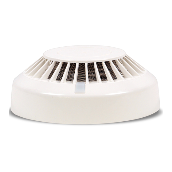
Designer's Tables - Detection Unit
Designer's Tables - Extinguishing Unit
Appendix A: POLON 4000 System Line Elements
Table of Contents
Print
Rename the bookmark
Delete bookmark?
Delete from my manuals?
Login
Sign In
OR
Sign in with Facebook
Sign in with Google
Upload manual
Upload from disk
Upload from URL
Need help?
Do you have a question about the 4500 and is the answer not in the manual?
Questions and answers