Advertisement
Quick Links
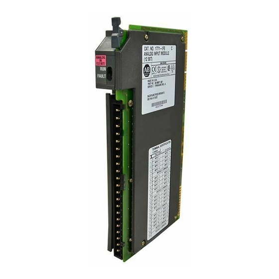
(Catalog Number 1771-IFE/C)
Use this document as a guide when installing the 1771-IFE/C analog
input module.
The analog input module is sensitive to electrostatic discharge.
ATTENTION: Electrostatic discharge can damage
integrated circuits or semiconductors if you touch
!
backplane connector pins. Follow these guidelines
when you handle the module:
Touch a grounded object to discharge static potential
Wear an approved wrist-strap grounding device
Do not touch the backplane connector or
connector pins
Do not touch circuit components inside the module
If available, use a static-safe work station
When not in use, keep the module in its
static-shield box
Installation Instructions
Advertisement

Related Manuals for Allen-Bradley 1771-IFE


Summary of Contents for Allen-Bradley 1771-IFE
- Page 1 Installation Instructions (Catalog Number 1771-IFE/C) Use this document as a guide when installing the 1771-IFE/C analog input module. The analog input module is sensitive to electrostatic discharge. ATTENTION: Electrostatic discharge can damage integrated circuits or semiconductors if you touch backplane connector pins. Follow these guidelines...
- Page 2 Allen-Bradley publications: The 1771-IFE module can be used with any 1771 I/O chassis. Compatibility and data table use is listed below. Do not use this module with cat. no. 1771-AL PLC-2/20 or 2/30...
- Page 3 Series C applications. This setting returns input data above and below the range end points. If you are replacing a Series A or B 1771-IFE module with this module, reset the simulation jumper to the position as shown below.
- Page 4 A/B simulation jumper set for Series C. If you are replacing a Series A or B 1771-IFE module with this module, reset the simulation jumper as shown above. You can select either voltage or current for each input, but all inputs must be either single-ended or differential.
- Page 5 Analog Input Module ATTENTION: Remove power from the 1771 I/O chassis backplane and field wiring arm before removing or installing an I/O module. Failure to remove power from the backplane or wiring arm could cause module damage, degradation of performance, or injury. Failure to remove power from the backplane could cause injury or equipment damage due to possible unexpected operation.
- Page 6 Failure to remove power from the backplane could cause injury or equipment damage due to possible unexpected operation. Input connections for the 1771-IFE module with: single-ended inputs are shown on page differential inputs are shown on page 8 To minimize ground-loop currents on input circuits:...
- Page 7 Analog Input Module – –...
- Page 8 Analog Input Module – – – –...
- Page 9 Analog Input Module Use the following diagrams to ground your I/O chassis and analog input module. Follow these steps to prepare the cable: Refer to Industrial Automation Wiring and Grounding Guidelines for Noise Immunity, publication 1770-4.1, for additional information.
- Page 10 Analog Input Module Because of the many analog devices available and the wide variety of possible applications, you must configure the module to conform to the analog device and specific application that you have chosen. Use the configuration information below to configure your module to your specifications.
- Page 11 Analog Input Module Use the following table to read data from your input module.
- Page 12 Analog Input Module If a write block of five words with all zeroes is sent to the module, default selections will be: 1 to 5V dc or 4 to 20mA (dependent on configuration jumper setting) BCD data format no real time sampling (RTS) no filtering no scaling single-ended inputs...
- Page 13 Analog Input Module Possible module fault causes and corrective action is described in the following table.
- Page 14 Analog Input Module Î Î Î Î Î Î Î Î Î Î...
- Page 15 Analog Input Module...
- Page 16 Analog Input Module...
Need help?
Do you have a question about the 1771-IFE and is the answer not in the manual?
Questions and answers