Allen-Bradley 1734-IE2C Installation Instructions Manual
Point i/o 2 input analog module series c
Hide thumbs
Also See for 1734-IE2C:
- Installation instructions manual (22 pages) ,
- User manual (221 pages) ,
- Installation instructions manual (12 pages)
Table of Contents
Advertisement
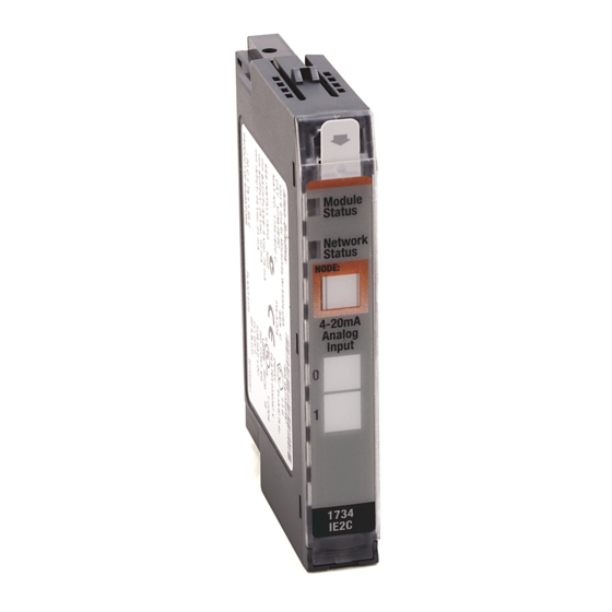
POINT I/O 2 Input Analog Module
(Cat. No. 1734-IE2C Series C)
4
3
Description
1
Mounting Base
2
Mechanical Keying (orange)
3
Module Wiring Diagram
4
Module Locking Mechanism
5
Insertable I/O Module
1
Wiring Base Assembly consists of item 1) mounting base, 1734-MB and item 7) removable
terminal block, 1734-RT or -RTS.
POINT I/O is a trademark of Rockwell
DeviceNet is a trademark of ODVA, Inc.
9
2
8
10
1
1
Automation1
Installation Instructions
5
6
7
Description
6
RTB Removal Handle
7
Removable Terminal Block (RTB)
8
DIN Rail Locking Screw (orange)
9
Slide-in Writable Label
10
Interlocking Side Pieces
Publication 1734-IN053C-EN-P - April 2002
1
Advertisement
Table of Contents

Related Manuals for Allen-Bradley 1734-IE2C


Summary of Contents for Allen-Bradley 1734-IE2C
- Page 1 Installation Instructions POINT I/O 2 Input Analog Module (Cat. No. 1734-IE2C Series C) Description Description RTB Removal Handle Mounting Base Mechanical Keying (orange) Removable Terminal Block (RTB) Module Wiring Diagram DIN Rail Locking Screw (orange) Module Locking Mechanism Slide-in Writable Label...
-
Page 2: Important User Information
In no event will Allen-Bradley be responsible or liable for indirect or consequential damage resulting from the use or application of these products. - Page 3 POINT I/O 2 Input Analog Module Identifies information about practices or ATTENTION circumstances that can lead to personal injury or death, property damage, or economic loss. Identifies information that is critical for IMPORTANT successful application and understanding of the product. Publication 1734-IN053C-EN-P - April 2002...
- Page 4 60529, as applicable, for explanations of the degrees of protection provided by different types of enclosure. Also, see the appropriate sections in this publication, as well as the Allen-Bradley publication 1770-4.1 ("Industrial Automation Wiring and Grounding Guidelines"), for additional installation requirements pertaining to this equipment.
-
Page 5: Explosion Hazard
POINT I/O 2 Input Analog Module EXPLOSION HAZARD WARNING • Do not disconnect equipment unless power has been removed or the area is known to be nonhazardous. • Do not disconnect connections to this equipment unless power has been removed or the area is known to be nonhazardous. -
Page 6: Installing The Mounting Base
POINT I/O 2 Input Analog Module Installing the Mounting Base To install the mounting base on the DIN rail, proceed as follows. 1. Position the mounting base vertically above the installed units (adapter, power supply or existing module. 2. Slide the mounting base down allowing the interlocking side pieces to engage the adjacent module or adapter. -
Page 7: Installing The Removable Terminal Block (Rtb)
POINT I/O 2 Input Analog Module 3. Insert the module straight down into the mounting base and press to secure. The module will lock into place. Installing the Removable Terminal Block (RTB) A removable terminal block is supplied with your wiring base assembly. To remove, pull up on the RTB handle. -
Page 8: Removing A Mounting Base
POINT I/O 2 Input Analog Module Removing a Mounting Base To remove a mounting base, you must remove any installed module, and the module installed in the base to the right. Remove the removable terminal block (if wired). 1. Unlatch the RTB handle on the I/O module. 2. -
Page 9: Communicating With Your Module
This POINT I/O input module produces 6 bytes of input data (scanner Rx) and fault status data. It does not consume I/O data (scanner Tx). Default Data Map for the 1734-IE2C Analog Input Module Message size: 6 Bytes Produces... -
Page 10: Wiring The Input Analog Module
POINT I/O 2 Input Analog Module Wiring the Input Analog Module Module Status Module Status Network Status Network Status NODE: 4-20mA Analog Input Status of Input 0 Status of Input 1 1734 IE2C Input 1 Connection Input 0 Connection Chas Gnd Chas Gnd 41974 Chas Gnd = Chassis ground... -
Page 11: Troubleshooting With The Indicators
POINT I/O 2 Input Analog Module Troubleshooting with the Indicators Module Status Module Status Network Status Network Status NODE: 4-20mA Analog Input Status of Input 0 Status of Input 1 1734 IE2C Indication Probable Cause Module Status No power applied to device Green Device operating normally Flashing Green... - Page 12 POINT I/O 2 Input Analog Module Indication Probable Cause Network Status Device is not on-line - Device has not completed dup_MAC_id test. - Device not powered - check module status indicator Flashing Green Device is on-line but has no connections in the established state.
-
Page 13: Safety Approvals
• S’assurer que l’environnement est they must only be changed in an area known to be nonhazardous. classé non dangereux avant de changer les piles. Specifications - 1734-IE2C/C 2 Input Analog Module Input Specifications Number of Inputs 2 single-ended, non-isolated Resolution 16 bits - over 0-21mA 0.32µA/cnt... - Page 14 POINT I/O 2 Input Analog Module Input Update Rate 100ms @ Notch = 60Hz (default) (per module) 120ms @ Notch - 50Hz 24ms @ Notch = 250Hz 12ms @ Notch = 500Hz Step Response 70ms @ Notch = 60Hz (default) (per channel) 80ms @ Notch = 50Hz 16ms@ Notch = 250Hz...
- Page 15 POINT I/O 2 Input Analog Module Environmental Conditions Operational IEC 60068-2-1 (Test Ad, Operating Cold), Temperature IEC 60068-2-2 (Test Bd, Operating Dry Heat), IEC 60068-2-14 (Test Nb, Operating Thermal Shock): -20 to 55°C (-4 to 131°F) Storage Temperature IEC 60068-2-1 (Test Ab, Unpackaged Nonoperating Cold), IEC 60068-2-2 (Test Bb, Unpackaged Nonoperating Dry Heat),...
- Page 16 Conductors Wire Size 14 AWG (2.5mm ) - 22 AWG (0.25mm ) shielded solid or stranded shielded copper wire rated at 75°C or greater 3/64 inch (1.2mm) insulation maximum Category Terminal Base Screw Torque 7 pound-inches (0.6Nm) Field Wiring Terminations 0 - Input 0 1 - Input 1 2 - Ground 0...
Need help?
Do you have a question about the 1734-IE2C and is the answer not in the manual?
Questions and answers