Sign In
Upload
Download
Table of Contents
Contents
Add to my manuals
Delete from my manuals
Share
URL of this page:
HTML Link:
Bookmark this page
Add
Manual will be automatically added to "My Manuals"
Print this page
×
Bookmark added
×
Added to my manuals
Manuals
Brands
Allen-Bradley Manuals
I/O Systems
1746-NIO4V
User manual
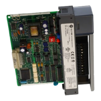
Allen-Bradley 1746-NIO4V User Manual
4-channel analog i/o modules
Hide thumbs
1
2
3
4
Table Of Contents
5
6
7
8
9
10
11
12
13
14
15
16
17
18
19
20
21
22
23
24
25
26
27
28
29
30
31
32
33
34
35
36
37
38
39
40
41
42
43
44
45
46
47
48
49
50
51
52
53
54
55
56
57
58
59
60
61
62
63
64
65
66
67
68
69
70
71
72
73
74
75
76
77
78
79
80
81
82
83
84
85
86
87
88
89
90
91
92
93
94
95
96
97
98
99
100
101
102
103
104
105
106
107
108
109
110
111
112
113
page
of
113
Go
/
113
Contents
Table of Contents
Troubleshooting
Bookmarks
Table of Contents
Table of Contents
Preface
Who Should Use this Manual
Purpose of this Manual
Related Documentation
Common Techniques Used in this Manual
Your Questions or Comments on this Manual
Overview
How to Use Analog
Types of Analog Modules
1746-NI4 Analog Input Module
1746-NIO4I and NIO4V Analog Combination Modules
1746-NO4I and NO4V Analog Output Modules
Quick Start for Experienced Users
Required Tools and Equipment
Procedures
Installing and Wiring Your Analog Module
European Union Directive Compliance
EMC Directives
Determining Your Power Requirements for a Modular Controller
Determining Your Power Requirements for a Fixed Controller
Configuring Your Module
Switch Settings for the 1746-NI4
Switch Settings for the 1746-NIO4I and -NIO4V
External Power Switch for the 1746-NO4I and -NO4V
Choosing a Slot in the Chassis
Installing Your Module
Removing the Analog Module Terminal Block
Wiring Considerations
System Wiring Guidelines
Grounding Your Cable
Determining the Cable Length
Wiring the Analog Module
Labeling and Installing the Terminal Block
Grounding the Foil Shields and Drain Wires
Wiring Schematics for 2, 3, and 4-Wire Analog Input Devices
Wiring Schematic for Single-Ended Analog Input Connections
Minimizing Electrical Noise on Analog Modules
Interface between the Module and the Processor
Entering Module ID Codes
Addressing Analog Modules
Bit Level Addressing
Processor Update of Analog Data
Monitoring the Input and Output Data
Converting Analog Input Data
Converting Analog Output Data
System Considerations
Safe State for Outputs
Retentive Programming Option
Retentive Analog Output Example
Non-Retentive Analog Output Example
During a Mode Change or Power Cycle
Input Out-Of-Range Detection
Response to Slot Disable
Input Response to Slot Disable
Output Response to Slot Disable
Input Channel Filtering
Testing the SLC 500 System
Start-Up Procedures
Inspect the Analog Module
Disconnect Prime Movers (Motion Devices)
Power up the SLC 500 System
Testing Analog Inputs
Testing Analog Outputs
Addressing, Out-Of-Range Detection, and Scaling of Analog
Inputs
Calculating the Linear Relationship
Calculating the Out-Of-Range Flag Using the Scale Instruction
Using Standard Math
Using the Scale (SCL) Instruction
Using Scale with Parameters (SCP) Instruction
Addressing and Scaling Outputs
Calculating the Linear Relationship
Using Standard Math
Using the Scale with Parameters (SCP) Instruction
Scaling Offset When > 32,767 or < -32,768
Calculating the Linear Relationship
Calculating the Shifted Linear Relationship
Using Standard Math
Using the Scale with Parameters (SCP) Instruction
Scaling and Range Checking and Analog Inputs and Outputs
Calculating the Linear Relationship
Using Standard Math Instructions
Scaling and Range Checking of Analog Inputs and Outputs
Using SCL Instruction
Using the Scale with Parameters (SCP) Instruction
Preventative Maintenance
Safety Considerations When Troubleshooting
Analog Modules Specification
General Specifications for NI4, NIO4I, NIO4V, NO4I, and NO4V
Nio4V
Current-Loop Input Specifications for NI4, NIO4I, and NIO4V
Voltage Input Specifications for NI4, NIO4I, and NIO4V
Current Output Specifications for NIO4I and NO4I
Voltage Output Specifications for NIO4V and NO4V
Positive Decimal Values
Negative Decimal Values
Calibrating an Analog Input Channel
Calculating the Software Calibration
Advertisement
Quick Links
Download this manual
SLC™ 500
4-Channel Analog
I/O Modules
(Catalog Numbers 1746-NI4,
1746-NIO4I, 1746-NIO4V,
1746-NO4I, and 1746-NO4V)
User Manual
Table of
Contents
Previous
Page
Next
Page
1
2
3
4
5
Advertisement
Table of Contents
Need help?
Do you have a question about the 1746-NIO4V and is the answer not in the manual?
Ask a question
Questions and answers
Related Manuals for Allen-Bradley 1746-NIO4V
I/O Systems Allen-Bradley SLC 500 Installation Instructions Manual
Digital (48 pages)
I/O Systems Allen-Bradley 1746 Series Installation Instructions Manual
Discrete i/o modules, combination input/output module (56 pages)
I/O Systems Allen-Bradley 1746-IA4 Installation Instructions Manual
Digital i/o modules (48 pages)
I/O Systems Allen-Bradley 1747-ASB Installation Instructions Manual
Remote i/o adapter module (20 pages)
I/O Systems Allen-Bradley SLC500 Installation Instructions Manual
Thermocouple/mv analog input module (20 pages)
I/O Systems Allen-Bradley 1746-NT8 User Manual
Thermocouple/mv analog input module (110 pages)
I/O Systems Allen-Bradley 1746-INT4 Quick Start
Thermocouple/mv isolated input module (4 pages)
I/O Systems Allen-Bradley B Series User Manual
Thermocouple/mv isolated input module (106 pages)
I/O Systems Allen-Bradley 1746-NIO4I User Manual
4-channel analog i/o modules (113 pages)
I/O Systems Allen-Bradley 1746-NO4I User Manual
4-channel analog i/o modules (113 pages)
I/O Systems Allen-Bradley 1746-NI4 User Manual
4-channel analog i/o modules (113 pages)
I/O Systems Allen-Bradley 1746-NO4V User Manual
4-channel analog i/o modules (113 pages)
I/O Systems Allen-Bradley 1771 Manual
(8 pages)
I/O Systems Allen-Bradley 1734-OE4C Installation Instructions Manual
Point i/o 4 channel analog current output module (22 pages)
I/O Systems Allen-Bradley 1756-IF8I User Manual
High resolution analog i/o modules (226 pages)
I/O Systems Allen-Bradley CompactBlock LDX 1790D-T4T0 User Manual
I/o thermocouple modules (112 pages)
Summarization of Contents
Important User Information
Safety Guidelines for the Application, Installation and Maintenance of Solid State Controls
Describes differences between solid state and electromechanical controls.
Responsibility and Liability
Rockwell Automation is not liable for indirect or consequential damages.
Illustrative Purposes
Examples and diagrams are for illustration only.
Patent Liability
No patent liability is assumed.
Reproduction of Manual
Reproduction requires written permission.
Safety Considerations
Manual uses notes for safety awareness.
WARNING
Identifies explosion hazards in hazardous environments.
IMPORTANT
Identifies critical information for successful application.
ATTENTION
Identifies practices leading to personal injury or damage.
SHOCK HAZARD
Alerts to dangerous voltage presence.
BURN HAZARD
Alerts to dangerous surface temperatures.
Summary of Changes
SCP (scale with parameters) instruction available with SLC™ 5/05
Mentions availability of a specific instruction.
Change in Impedance to ANL Com specification for NI4 Series B module
Details changes in impedance specifications for a module.
Change in Impedance Channel to Channel specification for NI4 Series B module
Details changes in channel-to-channel impedance.
Change in Input Impedance specification for NI4 Series B module
Details changes in input impedance specifications.
Change in resistance value for NI4 Series B module
Details changes in resistance values for a module.
Preface
Who Should Use this Manual
Identifies target audience for the manual.
Purpose of this Manual
Explains what the manual covers.
Related Documentation
SLC 500 Instruction Set Reference Manual
Lists a reference manual for instructions.
SLC 500 Modular Hardware Style User Manual
Lists a manual for modular hardware.
SLC 500 Fixed Hardware Style Installation & Operation Manual
Lists a manual for fixed hardware.
SLC 500 4-Channel Analog I/O Modules Installation Instructions
Lists installation instructions for analog modules.
System Design for Control of Electrical Noise
Provides information on reducing electrical noise.
Allen-Bradley Programmable Controller Grounding and Wiring Guidelines
Covers grounding and wiring guidelines.
Application Considerations for Solid-State Controls
Discusses differences in solid-state controls.
National Electrical Code
Article on wire sizes and types for grounding.
Allen-Bradley Industrial Automation Glossary
Provides a glossary of terms.
Common Techniques Used in this Manual
Bulleted lists
Provide information, not procedural steps.
Numbered lists
Provide sequential or hierarchical information.
Italic type
Used for emphasis.
Your Questions or Comments on this Manual
Chapter 1 Overview
How to Use Analog
Explains analog representation and application.
Types of Analog Modules
Provides an overview of various analog modules.
Chapter 2 Quick Start for Experienced Users
Required Tools and Equipment
Lists necessary tools and equipment.
1. Check the contents of shipping box.
2. Determine your power requirements for the modular controller.
3. Configure the module using the DIP switches (analog inputs only).
4. Install your module.
5. Wire the module.
6. Configure system I/O configuration.
7. Check that the module is operating correctly.
8. Understanding analog inputs.
9. Understanding analog outputs.
10. Write ladder logic to process the module’s analog data.
Chapter 3 Installing and Wiring Your Analog Module
European Union Directive Compliance
Details compliance with EU directives.
EMC Directives
Explains EMC standards compliance.
Determining Your Power Requirements for a Modular Controller
Determining Your Power Requirements for a Fixed Controller
Configuring Your Module
Switch Settings for the 1746–NI4
Details DIP switch settings for the NI4 module.
Switch Settings for the 1746-NIO4I and -NIO4V
Details DIP switch settings for NIO4I/NIO4V modules.
External Power Switch for the 1746-NO4I and -NO4V
Choosing a Slot in the Chassis
Installing Your Module
Removing the Analog Module Terminal Block
Wiring Considerations
System Wiring Guidelines
Grounding Your Cable
Determining the Cable Length
Wiring the Analog Module
Labeling and Installing the Terminal Block
Grounding the Foil Shields and Drain Wires
Wiring Schematics for 2, 3, and 4-Wire Analog Input Devices
Wiring Schematic for Single-ended Analog Input Connections
Minimizing Electrical Noise on Analog Modules
Chapter 4 Module Operation and System Considerations
Interface between the Module and the Processor
How to set up an analog module in an SLC 500 system.
Entering Module ID Codes
Procedure to enter module identification codes.
Addressing Analog Modules
NI4
How the NI4 module is addressed.
NIO4I and NIO4V
Addressing for NIO4I and NIO4V modules.
NO4I and NO4V
Addressing for NO4I and NO4V modules.
Bit Level Addressing
Processor Update of Analog Data
Monitoring the Input and Output Data
Converting Analog Input Data
Converting Analog Output Data
System Considerations
Safe State for Outputs
How outputs behave when system is not in RUN mode.
Retentive Programming Option
How analog data is retained during mode changes.
Retentive Analog Output Example
Non-Retentive Analog Output Example
During a Mode Change or Power Cycle
Input Out-of-Range Detection
Response to Slot Disable
Input Response to Slot Disable
Input behavior when slot is disabled.
Output Response to Slot Disable
Output behavior when slot is disabled.
Input Channel Filtering
Chapter 5 Testing Your Module
Testing the SLC 500 System
Testing the SLC 500 system before analog module tests.
Start-up Procedures
Steps to follow for analog module testing.
Inspect the Analog Module
Disconnect Prime Movers (Motion Devices)
Power Up the SLC 500 System
Testing Analog Inputs
Testing Analog Outputs
Chapter 6 Programming Examples
Addressing, Out-of-Range Detection, and Scaling of Analog Inputs
Examples for addressing, range checking, and scaling inputs.
Calculating the Linear Relationship
Calculating the Out-of-Range Flag Using the Scale Instruction
Using Standard Math
Using the Scale (SCL) Instruction
Using Scale with Parameters (SCP) Instruction
Addressing and Scaling Outputs
Calculating the Linear Relationship
Equations for calculating scaled output values.
Scaling Offset when > 32,767 or < -32,768
Scaling and Range Checking and Analog Inputs and Outputs
Scaling and Range Checking of Analog Inputs and Outputs
Using SCL Instruction
Using the Scale with Parameters (SCP) Instruction
Chapter 7 Maintenance and Safety
Preventative Maintenance
Information on maintaining the SLC 500 system.
Safety Considerations When Troubleshooting
Appendix A Specifications
Analog Modules Specification
Lists specifications for analog modules.
General Specifications for NI4, NIO4I, NIO4V, NO4I, and NO4V
General specs for specific analog modules.
General Analog Input Specifications for NI4, NIO4I, and NIO4V
Current-Loop Input Specifications for NI4, NIO4I, and NIO4V
Voltage Input Specifications for NI4, NIO4I, and NIO4V
Current Output Specifications for NIO4I and NO4I
Voltage Output Specifications for NIO4V and NO4V
Appendix B Two’s Complement Binary Numbers
Positive Decimal Values
Explains positive decimal values in binary notation.
Negative Decimal Values
Appendix C Optional Analog Input Software Calibration
Calibrating an Analog Input Channel
Procedure for calibrating analog input channels.
Calculating the Software Calibration
Example Ladder Diagram
Appendix D Module Input and Output Circuits
Input Circuit for 1746-NI4, -NIO4I, and -NIO4V Modules
Circuit diagram for input modules.
Voltage Output Circuit for 1746-NIO4V Modules
Circuit diagram for voltage output modules.
Current Output Circuit for 1746-NIO4I Modules
Circuit diagram for current output modules.
Module Input and Output Circuits
Table of Contents
Print
Rename the bookmark
Delete bookmark?
Delete from my manuals?
Login
Sign In
OR
Sign in with Facebook
Sign in with Google
Upload manual
Upload from disk
Upload from URL
Need help?
Do you have a question about the 1746-NIO4V and is the answer not in the manual?
Questions and answers