Advertisement
Table of Contents
- 1 Table of Contents
- 2 Important User Information
- 3 Environment and Enclosure
- 4 Preventing Electrostatic Discharge
- 5 About the Module
- 6 Install the Mounting Base
- 7 Install the Module
- 8 Install the Removable Terminal Block
- 9 Wire the Module
- 10 Communicate with the Module
- 11 Interpret Status Indicators
- 12 Specifications
- Download this manual
See also:
Instruction and Installation Manual
Installation Instructions
POINT I/O 4 Channel IO-Link
Master Module
Catalog number 1734-4IOL
Table of Contents
Topic
Page
2
3
3
5
7
8
9
11
13
15
17
Advertisement
Table of Contents

Related Manuals for Allen-Bradley 1734-4IOL


Summary of Contents for Allen-Bradley 1734-4IOL
-
Page 1: Table Of Contents
Installation Instructions POINT I/O 4 Channel IO-Link Master Module Catalog number 1734-4IOL Table of Contents Topic Page Important User Information Environment and Enclosure Preventing Electrostatic Discharge About the Module Install the Mounting Base Install the Module Install the Removable Terminal Block... -
Page 2: Important User Information
2 POINT I/O 4 Channel IO-Link Master Module Important User Information Solid-state equipment has operational characteristics differing from those of electromechanical equipment. Safety Guidelines for the Application, Installation and Maintenance of Solid State Controls (Publication SGI-1.1 available from your local Rockwell Automation sales office or online at http://www.rockwellautomation.com/literature/) describes some important differences between solid-state equipment and hard-wired electromechanical devices. -
Page 3: Environment And Enclosure
POINT I/O 4 Channel IO-Link Master Module Environment and Enclosure ATTENTION: This equipment is intended for use in a Pollution Degree 2 industrial environment, in overvoltage Category II applications (as defined in IEC 60664-1), at altitudes up to 2000 m (6562 ft) without derating. This equipment is not intended for use in residential environments and may not provide adequate protection to radio communication services in such environments. - Page 4 4 POINT I/O 4 Channel IO-Link Master Module ATTENTION: This product is grounded through the DIN rail to chassis ground. Use zinc plated yellow-chromate steel DIN rail to assure proper grounding. The use of other DIN rail materials (for example, aluminum or plastic) that can corrode, oxidize, or are poor conductors, can result in improper or intermittent grounding.
-
Page 5: About The Module
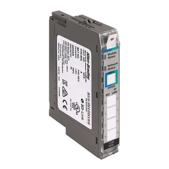
POINT I/O 4 Channel IO-Link Master Module About the Module The POINT I/O 4 Channel IO-Link Master Module provides four channels that can be individually configured as IO-Link master or as a standard digital I/O module. The IO-Link channel master module can be configured to fit any IO-Link and/or discrete application. - Page 6 6 POINT I/O 4 Channel IO-Link Master Module Description Description Module locking mechanism Terminal base Slide-in writable label Interlocking side pieces Insertable I/O module Mechanical keying (orange) Removable terminal block (RTB) handle DIN rail locking screw (orange) Removable terminal block Module wiring diagram POINT I/O 4 Channel IO-Link Master Module with 1734-TOP, 1734-TOPS, 1734-TOP3, or 1734-TOP3S One-Piece Terminal Base...
-
Page 7: Install The Mounting Base
POINT I/O 4 Channel IO-Link Master Module Install the Mounting Base To install the mounting base on the DIN rail, proceed as follows: 1. Position the mounting base vertically above the installed units (adapter, power supply or existing module). Slide the mounting base until the interlocking side pieces engage the adjacent module or adapter. -
Page 8: Install The Module
8 POINT I/O 4 Channel IO-Link Master Module Install the Module The module can be installed before or after base installation. Make sure that the mounting base is correctly keyed before installing the module into the mounting base. In addition, make sure the mounting base locking screw is positioned horizontal referenced to the base. -
Page 9: Install The Removable Terminal Block
POINT I/O 4 Channel IO-Link Master Module 4. Press to secure. The module locks into place. 44013 Install the Removable Terminal Block A removable terminal block (RTB) is supplied with your wiring base assembly. To remove, pull up on the RTB handle. This allows the mounting base to be removed and replaced as necessary without removing any of the wiring. - Page 10 10 POINT I/O 4 Channel IO-Link Master Module 3. If an I/O module is installed, snap the RTB handle into place on the module. Insert the module straight down into the mounting base. Hook the RTB end into the mounting base end and rotate until it locks into place.
-
Page 11: Wire The Module
POINT I/O 4 Channel IO-Link Master Module Wire the Module To wire the module, refer to the diagrams and tables. POINT I/O 4 Channel IO-Link Master Module – 1734-4IOL 1734-4IOL Channel 0 Channel 1 Channel 2 Channel 3 POINT I/O 4 Channel IO-Link Master Module Wiring - IO-Link Mode... - Page 12 12 POINT I/O 4 Channel IO-Link Master Module POINT I/O 4 Channel IO-Link Master Module Wiring - Standard Digital Input Mode In 0 In 1 2-wire 3-wire 3-wire 2-wire In 2 In 3 In = Input channel C = Common V = Voltage Channel Input...
-
Page 13: Communicate With The Module
POINT I/O modules send (produce) and receive (consume) I/O data (messages). You map this data into the processor’s memory. The consumed and produced connection sizes may range from 0...32 bytes. Default Data Map for 1734-4IOL – Configuration Assembly Instance 100 Message size: 46 Bytes Consumed Byte Bit 7... - Page 14 14 POINT I/O 4 Channel IO-Link Master Module Default Data Map for 1734-4IOL – Consumed Assembly Instance 101 Message size: 0...128 Bytes Consumed Byte Bit 7 Bit 6 Bit 5 Bit 4 Bit 3 Bit 2 Bit 1 Bit 0 b+1...c...
-
Page 15: Interpret Status Indicators
POINT I/O 4 Channel IO-Link Master Module Interpret Status Indicators Refer to the following diagram and table for information on how to interpret the status indicators. POINT I/O 4 Channel IO-Link Master Module – 1734-4IOL Module status Module Status Network status... - Page 16 16 POINT I/O 4 Channel IO-Link Master Module Indicator Status for Modules Status Description Module status No power applied to device. Green Device operating normally. Flashing green The device has not been configured. Flashing red Recoverable fault. One or more non-recoverable major faults detected. Flashing red/green Device is self-testing.
-
Page 17: Specifications
POINT I/O 4 Channel IO-Link Master Module Specifications General Specifications Attribute Value Number of inputs 4 single-ended, non-mutual isolated, configurable Number of outputs Communication rate, IO-Link 4.8 kB; 38.4 kB; 230.4 kB Device cable length, IO-Link, max 20 m Terminal base screw torque 0.8 Nm (7 lb-in.) Module location 1734-TB, 1734-TBS, 1734-TB3, 1734-TB3S, 1734-TOP, 1734-TOPS,... - Page 18 18 POINT I/O 4 Channel IO-Link Master Module POINT I/O 4 Channel IO-Link Master Module 1734-4IOL – Standard Digital Input Attribute Value On-state voltage, min 11V DC On-state current, min 2.0 mA On-state current, max 7.0 mA Off-state voltage, max...
- Page 19 POINT I/O 4 Channel IO-Link Master Module Environmental Specifications Attribute Value Temperature, operating IEC 60068-2-1 (Test Ad, Operating Cold), IEC 60068-2-2 (Test Bd, Operating Dry Heat), IEC 60068-2-14 (Test Nb, Operating Thermal Shock): -20…55 °C (-4…131 °F) Temperature, surrounding air, 55 °C (131 °F) max.
- Page 20 20 POINT I/O 4 Channel IO-Link Master Module Certifications Certification (when Value product is marked) c-UL-us UL Listed Industrial Control Equipment, certified for US and Canada. See UL File E322657. European Union 2004/108/EC EMC Directive, compliant with: EN 61326-1; Meas./Control/Lab., Industrial Requirements EN 61000-6-2;...
- Page 21 POINT I/O 4 Channel IO-Link Master Module Notes: Publication 1734-IN043A-EN-E - September 2015...
- Page 22 22 POINT I/O 4 Channel IO-Link Master Module Notes: Publication 1734-IN043A-EN-E - September 2015...
- Page 23 POINT I/O 4 Channel IO-Link Master Module Notes: Publication 1734-IN043A-EN-E - September 2015...
- Page 24 Rockwell Automation maintains current product environmental information on its website at http://www.rockwellautomation.com/rockwellautomation/about-us/sustainability-ethics/product-environmental-compliance.page. Allen-Bradley, Rockwell Automation, POINT I/O, RSLogix, and Studio 5000 are trademarks of Rockwell Automation, Inc. Trademarks not belonging to Rockwell Automation are property of their respective companies. Publication 1734-IN043A-EN-E - September 2015...
Need help?
Do you have a question about the 1734-4IOL and is the answer not in the manual?
Questions and answers