Table of Contents
Advertisement
Quick Links
KI51PV-754
Copyright
All rights are reserved. No part of this publication may be reproduced, transmitted, transcribed,
stored in a retrieval system or translated into any language or computer language, in any form
or by any means, electronic, mechanical, magnetic, optical, chemical, manual or otherwise,
without the prior written permission of the company. Brands and product names are trademarks
or registered trademarks of their respective companies.
The vendor makes no representations or warranties with respect to the contents herein and
especially disclaim any implied warranties of merchantability or fitness for any purpose. Further
the vendor reserves the right to revise this publication and to make changes to the contents
herein without obligation to notify any party beforehand. Duplication of this publication, in part or
in whole, is not allowed without first obtaining the vendor's approval in writing.
Trademark
All the trademarks or brands in this document are registered by their respective owner.
Disclaimer
We make no warranty of any kind with regard to the content of this user's manual. The content
is subject to change without notice and we will not be responsible for any mistakes found in this
user's manual. All the brand and product names are trademarks of their respective companies.
FCC Compliance Statement
This equipment has been tested and found to comply with the limits of a Class B digital device,
pursuant to Part 15 of the FCC Rules. These limits are designed to provide reasonable
protection against harmful interference in a residential installation. This equipment generates,
uses and can radiate radio frequency energy and, if not installed and used in accordance with
the instructions, may cause harmful interference to radio communications. Operation of this
equipment in a residential area is likely to cause harmful interference in which case the user will
be required to correct the interference at his own expense. However, there is no guarantee that
interference will not occur in a particular installation.
CE Mark
The device is in accordance with 89/336 ECC-ENC Directive.
Ver: EG101
Advertisement
Table of Contents

Related Manuals for Albatron KI51PV-754


Summary of Contents for Albatron KI51PV-754
-
Page 1: Fcc Compliance Statement
KI51PV-754 Copyright All rights are reserved. No part of this publication may be reproduced, transmitted, transcribed, stored in a retrieval system or translated into any language or computer language, in any form or by any means, electronic, mechanical, magnetic, optical, chemical, manual or otherwise, without the prior written permission of the company. -
Page 2: Operating System
KI51PV-754 nVIDIA nForce4 C51PV & MCP51 ® Supports Socket 754 Athlon ® (The power consumption for the aforementioned processors must be rated at 65W or less.) User’s Manual Dimensions (Micro-ATX Form-Factor): 170mm x 170mm ( W x L ) Operating System: Windows®... -
Page 3: Packing List
Do not touch any IC chip, lead, connector or other components. Always unplug the AC power when you install or remove any device on the mainboard or when confuguring pins and switches. Packing List KI51PV-754 mainboard I/O Bracket IDE Cable SATA Cable Mainboard Setup Driver &... -
Page 4: Table Of Contents
... 1 NTRODUCTION ... 2 PECIFICATION ... 5 ONFIGURATION Layout of KI51PV-754 (Right Side)... 5 Layout of KI51PV-754 (Back Side) ... 6 ARDWARE NSTALLATION CPU Processor Installation... 7 Memory Installation: DIMM1 ... 8 Back Panel Configuration... 9 Connectors... 11 Front Panel Headers: SW/LED, SPEAKER... 12 Headers &... -
Page 5: Chapter 1. Getting Started
The mainboard provides one PCI slot for use with a graphics card or expansion cards which the interfaces are compatible. The KI51PV-754 provides one floppy disk drive connector that can be used with 360KB/ 720KB/1.2MB/1.44MB/2.88MB drives. It also has two IDE connectors for hard drives supporting Ultra ATA 66/100/133. -
Page 6: Specification
Supports to use 184-pin, non-ECC & unbuffered DDR400 (PC3200)/ DDR333 (PC2700) SDRAM Slots: One PCI slot for expansion card FDC Connector: Supports one connector for two floppy disk drives Supports 360KB/720KB/1.2MB/1.44MB/2.88MB Mainboard KI51PV-754 64/ Sempron Processor (The power consumption for the Link Technology ® ® nForce4 C51PV ( nVIDIA... -
Page 7: Ide Connector
Support Sony/ Philips Digital Interfaces (S/PDIF) functionality Onboard LAN Chip: Supports 10/100/1000 Mbps Ethernet LAN ® Supports nVIDIA Active Armor ® Supports nVIDIA Firewall Mainboard KI51PV-754 which provides advanced data packet inspection to protect your system from hackers and viruses... -
Page 8: Watch Dog Timer
This function is used for detecting the system hangs during the POST stage due to conflicts resulting from changing the system BIOS settings. Once the problem is detected, the system will reset the configurations and reboot the system within five seconds. ABS (Albatron BIOS Security): Supports ABS Card (Optional) Supports BIOS backup Mainboard KI51PV-754... -
Page 9: Configuration
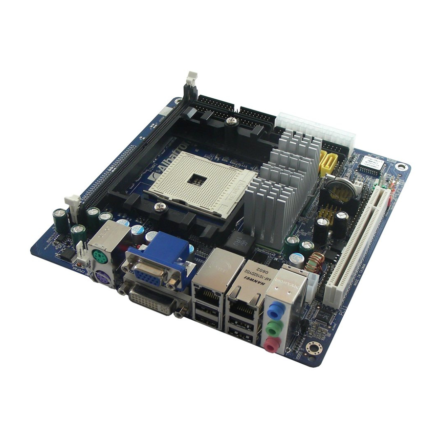
Mainboard KI51PV-754 Configuration Layout of KI51PV-754 (Right Side) -
Page 10: Layout Of Ki51Pv-754 (Back Side)
Mainboard KI51PV-754 Layout of KI51PV-754 (Back Side) -
Page 11: Hardware Installation
Finally, double-check that the cooling fan is properly installed and the CPU fan power cord is securely attached, in case your CPU and other sensitive components are damaged because of high temperatures. Mainboard KI51PV-754 64/ Sempron processor using Socket 754. Before... -
Page 12: Memory Installation: Dimm1
Memory Installation: DIMM1 The KI51PV-754 provides one DIMM (Dual In-Line Memory Modules) socket. It allows you to install 184-pin, non-ECC & unbuffered DDR400 (PC3200)/ DDR333 (PC2700) SDRAM that supports a total memory capacity of 1GB. -
Page 13: Back Panel Configuration
Repeat steps 1, 2 & 3 for the remaining memory and DIMM sockets setup. * The pictures shown above are for reference only. The actual installation may vary depending on models. Back Panel Configuration Mainboard KI51PV-754... - Page 14 There are four onboard USB 2.0/ 1.1 ports on the back panel. These USB ports are used to attach with USB devices, such as keyboard, mice and other USB supported devices. There are also one 10/100 Mbps and one 1Gbps Ethernet LAN ports available for you to attach an internet cable. Mainboard KI51PV-754 Assignment Assignment Data...
-
Page 15: Connectors
The IDE2 connector can also be attached with two IDE HDDs, and remember to configure one drive as the Master and the other one as the Slave as well. In addition, it is recommended that attach the optical devices such as CD-ROM, DVD-ROM, etc. onto this IDE2 connector. Mainboard KI51PV-754... -
Page 16: Front Panel Headers: Sw/Led, Speaker
Front Panel Headers: SW/LED, SPEAKER Assignment HDD LED (+) Hard Drive LED HDD LED (-) Reset Control (-) Reset Switch Reset Control (+) Mainboard KI51PV-754 Assignment Ground Ground Ground SW/LED Function Assignment Power LED (+) -
Page 17: Headers & Jumpers
This mainboard provides four onboard USB 2.0/1.1 ports (back panel) that attach to USB devices. There are two additional USB headers that can be connected by cables to four more USB ports on the front panel of your case giving you a maximum of eight USB ports. USB1/2 Mainboard KI51PV-754 Assignment Assignment PC_BEEP... - Page 18 The infrared sensing device attached to this header can support to provide wireless infrared. You can transfer data connectionless to or from the portable device (i.e., laptop, PDA, etc.) which with this header attached. IrDA Mainboard KI51PV-754 TV_OUT Assignment C OUT...
- Page 19 This mainboard provides a PRT header for you connecting an external printer connector on the back panel of your case. Attaching the printer connector cable (Optional) onto this header, then you can use this printer connector to attach with a printer. Mainboard KI51PV-754 Assignment RIN1...
-
Page 20: Clear Cmos Jumper: Jp1
3. Wait several seconds. 4. Set JP1 header to ON (1-2 closed). 5. Connect the AC power cable and turn on your system. 6. Reset your new password. Mainboard KI51PV-754 Assignment S1 sleep mode (CPU stopped, DRAM refreshed, system running in low power... -
Page 21: Audio Configuration
You can use both the front audio panel and back panel audio simultaneously. If you are not using front panel audio ports, leave the jumper caps on the header pins (Note: pins 5&6 and 9&10) to avoid problems with the back panel audio ports. Mainboard KI51PV-754 SPDIF Assignment Ground... -
Page 22: Slots
Front out_L Slots PCI Slot: PCI1 PCI stands for Peripheral Component Interconnect, which is a bus standard for installing expansion cards such as network card, SCSI card, etc. to these PCI slots. Mainboard KI51PV-754 FRONT AUDIO Assignment Ground Audio power +5V... -
Page 23: Power Supply Attachments
Attention In general, power cords are designed and should be attached with a specific direction. The black wire of the power cord is Ground and should be attached onto the header location of Ground. Mainboard KI51PV-754 Assignment +3.3V +3.3V Ground... -
Page 24: Chapter 2. Bios Setup
Main Menu – Quit and do not save changes into CMOS Status Page Setup Menu and Option Page Setup Menu – Exit F1 key F5 key F6 key Mainboard KI51PV-754 BIOS includes additional features such as virus and Function Move to previous option Move to next option... -
Page 25: Main Menu
Mainboard KI51PV-754 Main Menu When you enter the PHOENIX-AWARD™ BIOS Utility, the Main Menu will appear on the screen. The Main menu allows you to select from several configuration options. Use the left/right arrow keys to select a particular configuration screen from the top menu bar or use the... - Page 26 Base Memory Extended Memory Total Memory Mainboard KI51PV-754 Description Set the system date. Note that the ‘Day’ automatically changes when you set the date. Set the current time of the system. Press <Enter> to enter the sub menu.
-
Page 27: Advanced Bios Features
80 tracks. Only 360 KB floppy drivers have 40 tracks. Drives with 720 KB, 1.2 MB and 1.44 MB drive capacities have 80 tracks. Because very few modern PCs have 40-tracks floppy driver, we recommend that you set this option to “Disabled”. Options: Enabled, Disabled (Default) Advanced BIOS Features Mainboard KI51PV-754... - Page 28 This option determines how many characters per second are generated when a key is held down. Options: 6 (Default), 8, 10, 12, 15, 20, 24, 30 Typematic Delay (Msec) This option represents the delay value before keystrokes begin to repeat. Options: 250 (Default), 500, 750, 1000 APIC Mode Mainboard KI51PV-754...
-
Page 29: Advanced Chipset Features
This option allows you to select DRAM Active to Precharge Delay. Options: Auto, 5T, 6T, 7T, 8T (Default), 9T, 10T, 11T, 12T, 13T, 14T, 15T RAS# to CAS# delay (Trcd) This option allows setting the RAS# to CAS# delay to Rd/Wr command on the same bank. Mainboard KI51PV-754... -
Page 30: Pnp/Pci Configurations
This option allows you to set up the PCI Latency Time (0-255). If you select “32” it will optimize PCI speeds. Options: 0-255, 32 (Default) **PCI Express relative items** Maximum Payload Size This item allows you to set the PCI-Express maximum payload size per time. Options: 128, 256, 512, 1024, 2048, 4096(Default) Frequency/Voltage Control Mainboard KI51PV-754... - Page 31 This option displays the result of your HT Ratio setting for Northbridge chipset. NB <—> SB HT Ratio This option allows you to set Hyper Transport frequency between Northbridge chipset and Southbridge chipset. Options: 1x, 2x, 3x, 4x(Default), 5x NB <—> SB HT Frequency Mainboard KI51PV-754...
-
Page 32: Integrated Peripherals
If you are familiar with the overclocking, we strongly recommend you to set the clock to the defult settings. We do not guarantee that damage will or will not occur when overclocking. Integrated Peripherals Mainboard KI51PV-754... -
Page 33: Init Display First
If you highlight the “RAID Config” label and then press the enter key, it will take you to a submenu with the following options. RAID Enable This allows you to enable or disable the RAID function. Options: Enabled, Disabled (Default) Mainboard KI51PV-754... -
Page 34: Onboard Device
Power On Function This option allows you to select a method of awakening the system from sleep mode. Options: Hot KEY, Mouse Left, Mouse Right, Any KEY, BUTTON ONLY (Default), Keyboard 98. Mainboard KI51PV-754... -
Page 35: Onboard Fdc Controller
If you select “On”, the system will boot whether or not the system was on before power failure. If you select “Former-Sts”, the system will be restored to the status before the power failure. Options: Off (Default), On, Former-Sts. Mainboard KI51PV-754... -
Page 36: Power Management
Maximum power management (only available for sl CPUs). Suspend Mode = 1 minute HDD Power Down = 1 minute 3. User Defined (Default) This option allows you to set each mode individually. Mainboard KI51PV-754 Power on Suspend Suspend to RAM POS and STR... -
Page 37: Video Off Method
Options: Disabled (Default), Enabled. RTC Wake Up When “Enabled”, you can set the date and time at which the RTC (real-time clock) alarm awakens the system from Suspend mode. Options: Enabled, Disabled (Default). Day of Month Alarm Mainboard KI51PV-754... -
Page 38: Time (Hh: Mm: Ss) Alarm
When this option is set to “Auto”, the system will auto control the CPU voltage and frequency depends the loading of system. Options: Auto, Disabled (Default). Hardware Monitor This menu is for monitoring the system status such as temperature, voltage, and so on. Load Defaults Mainboard KI51PV-754... -
Page 39: Exit Menu
Save all configuration changes to CMOS (memory) and exit setup. A confirmation message will be displayed before proceeding. Exit Without Saving Abandon all changes made during the current session and exit setup. A confirmation message will be displayed before proceeding. Mainboard KI51PV-754... -
Page 40: Chapter 3: Software Setup
When you insert the driver CD into the CD ROM, you’ll see the screen as the picture below. There are several buttons displayed in the main screen as shown below. Mainboard KI51PV-754 Platform Windows 2000 /XP... - Page 41 Microsoft DirectX9.0c – provides the software of Microsoft DirectX 9.0c. If you click the “Browse CD” button from the screen in step 1, you can browse all the files in the Driver CD. Click “Exit” button to exit the program. Mainboard KI51PV-754...
-
Page 42: Chapter 4: Troubleshooting
1. Check the cable running from the disk to the disk controller board. Make sure both ends are securely attached. Check the drive type in the standard CMOS setup. 2. Contact technical support. 3. Backing up the hard drive is extremely important. Make sure your periodically perform backups to avoid untimely disk crashes. Mainboard KI51PV-754... - Page 43 1. Reboot computer. Reinstall memory. Make sure that all memory modules are securely installed. 2. Use anti-virus programs to detect and clean viruses. Problem 9: Screen goes blank periodically. Causes: Screen saver is enabled. Solutions: Disable screen saver. Mainboard KI51PV-754...
- Page 44 Problem 14: Missing operating system on hard drive. Causes: CMOS setup has been changed. Solutions: Run setup and select the correct drive type. Problem 15: Certain keys do not function. Causes: Keys jammed or defective. Solutions: Replace keyboard. Mainboard KI51PV-754...
-
Page 45: Appendix I: Super 5.1 Channel Audio Effect Setup
2. Click Speaker Test button, you can see the screen like the pictures below. 3. Select the speaker which you want to test by clicking on it. 2 Channels Mainboard KI51PV-754 from the tool bar on the 4 Channels 6 Channels... -
Page 46: Appendix Ii: Raid Setup
Before you configure your RAID Array, you have to enable the “RAID Config” option in the BIOS Setup Utility. 1. After you boot your system, press the “Del” key when prompted to enter the BIOS Setup Utility. Mainboard KI51PV-754 stripe error correction information; the system can still read and As result,... - Page 47 Mainboard KI51PV-754 2. The “RAID config” option for enabling RAID will be found on the “Peripherals” screen as part of the “IDE Function Setup” section shown as below-left (Peripherals >> IDE Function Setup >> RAID config). Arrow down to the IDE RAID item and press enter.
- Page 48 Next, <Tab> over to the “Striping Block” option and press <Enter>. A pop menu will display as shown below. With this option you can manually select the striping block size for your array. This option will affect data access performance. We recommend that you to select “Optimal” option for automatic configuration. Press <Enter>. Mainboard KI51PV-754...
- Page 49 Mainboard KI51PV-754 Next, in the “Free Disks” section, you can use the up/down arrow keys to select disks to be used in your RAID array. After highlighting a disk, use the right-arrow key to activate the disk as part of the RAID Array. The selected disk will move over to the “Array Disks” section. You can use the left-arrow key to reverse your selection.
- Page 50 Mainboard KI51PV-754 RAID 1 mode (Array List) RAID 1 mode (Array Detail) Deleting an Array You can delete an existing array on the “Array Detail” screen. Press the <D> key. A warning/confirmation message will display (as shown below). Press <Y> to confirm.
- Page 51 Mainboard KI51PV-754 After the array is successfully deleted, the screen will display as shown below. Rebuilding a RAID Mirrored Array This section applies to Mirrored, Striped Mirroring RAID and RAID 5 configurations and describes how to reestablish the integrity of a mirrored environment after replacing one of the drives (typically because of a single disk failure).
- Page 52 Mainboard KI51PV-754 Before you rebuild a RAID Mirrored Array Before you begin rebuilding a RAID Mirrored Array, you must copy the “NvRaidMan.exe” file from the bundled CD Driver to your C: drive. [CD File Location Path => D: \ Driver \ nForce \ 6.53 \ IDE \ WIN2K (or WINXP)\ NvRaidMan.exe]...
- Page 53 Mainboard KI51PV-754 ® Install the OS of Windows 2000/XP into your RAID HDDs ® In this section, it will tell you how to install the operating system of Windows 2000/XP into your RAID drives. The installation steps below will assume that your HDDs have already been attached to either the PATA or SATA connectors, and also your BIOS RAID Utility has already been configured (see NVIDIA BIOS RAID Utility Configuration section).
-
Page 54: Appendix Iii: Abs (Albatron Bios Security) Card Setup
3. Remove the jumper caps (on pins 1-2, pins 3-4) from the mainboard BIOSCN1 header (figure 2). 4. Insert the ABS Card onto the BIOSCN1 header on the mainboard. The ABS will fit over the entire BIOSCN1 header and can only be inserted in one direction. Mainboard KI51PV-754 “Rescue Closed Closed (“Closed”... - Page 55 7. At the DOS prompt, type “DIR” and take notice of the name of the BIOS file name which ends with the extension “.bin” (e.g. K8N7003.bin”). There should also be an AWDFLASH.exe file present. Then type: awdflash(space)(the file name of .bin).bin (For example: awdflash(space) k8n7003.bin) Mainboard KI51PV-754 During the initial boot up Closed (“Closed” means putting a jumper cap onto two adjacent header pins.)
- Page 56 After the flash BIOS procedures have completed, press ‘F1’ to reboot the system. When the flash process is complete, press ‘F1’ Attention While processing the flash BIOS procedures, DO NOT power off or restart your system. Otherwise, it may damage the onboard BIOS. Mainboard KI51PV-754 Type Y...
- Page 57 Mainboard KI51PV-754 10. During the next boot sequence, enter the BIOS utility program (Note: During the boot sequence you will be given a chance to enter the BIOS utility by pressing the “DEL” key on most systems). Load the system with the default settings, and save the changes before exit the BIOS utility program.
- Page 58 ABS Card will fail the feature of providing BIOS backup. Therefore, it is recommended that recover the onboard BIOS in advance, and take the ABS Card as emergency happen. Mainboard KI51PV-754 BIOSCN1 “Onboard BIOS” as below, in order to...
Need help?
Do you have a question about the KI51PV-754 and is the answer not in the manual?
Questions and answers