Table of Contents
Advertisement
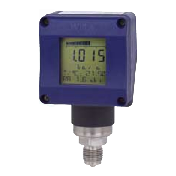
UT-10 / UT-11
Universal Transmitter for various applications
Universaltransmitter für vielfältige Einsatzgebiete
Transmetteur unviersel pour utilisations multiples
WIKA Alexander Wiegand GmbH & Co. KG
Alexander-Wiegand-Straße 30
63911 Klingenberg
Germany
/
Tel.
(+49) 93 72/132-295
Fax
(+49) 93 72/132-706
E-Mail support-tronic@wika.de
www.wika.de
Operating instructions
Betriebsanleitung
Mode d'emploi
UT-11
GB
GB
D
GB F
UT-10
Advertisement
Table of Contents

Related Manuals for WIKA UniTrans UT-11


Summarization of Contents
Product Description
Construction
Details the physical components and modular design of the UniTrans transmitter.
Pressure Transducer
Explains the piezo-resistive or thinfilm measurement cell, temperature compensation, and leak-testing.
Processing Unit
Describes the integrated control interface, keypad, and signal conversion to 4-20 mA.
Display Unit
Details the indicator's segments, symbols, error codes, and data display modes.
Function
Explains signal conversion, microelectronics processing, and extended functions for display versions.
Functions of Transmitters without Displays
Lists functions like zero/span calibration, dampening setting, and reset to defaults.
Functions of Transmitters with Displays
Details settable units, Min/Max values, calibration, damping, inversion, and more.
Installation Examples
Illustrates typical applications for process pressure measurement in pipes, tanks, and filters.
Technical Data
Input Values and Pressure Ranges
Specifies pressure ranges, overpressure limits, and burst pressures for absolute and relative measurements.
Output Values and Specifications
Details output signal, accuracy, turn down behavior, overall deviation, load, and fault signal.
Construction and Materials
Lists process connections, housing materials, wetted parts, and internal transmission fluid.
Auxiliary Power Supply
Specifies the DC power supply voltage range required for operation.
Ambient Conditions
Details ambient and storage temperature, climate class, ingress protection, and CE conformity.
Process Conditions
Defines medium temperature limits for different process connections, including EHEDG versions.
Identification Plates
Shows an example of the transmitter's identification plate with signal, power, serial, product, and code information.
Installation Guide
Pressure Transmitter Installation
Provides guidelines for installing the transmitter, including diaphragm protection and weld-on adapter use.
Display Unit Upgrades
Explains how to easily upgrade the display unit at any time, including mounting angles.
Housing Reconfiguration
Describes how to rotate the display unit's housing for better readability under various installation conditions.
Electrical Connection
Details wiring regulations, supply voltage, two-wire cable connection, and lightning protection.
Pressure Compensation for Relative Sensors
Explains Goretex diaphragm for atmospheric compensation and capillary cables for IP 67 protection.
Operation of Transmitters without Display
Preparation for Operation
Covers programming before or after installation, connecting an ampere meter, and verification of actions.
Key Functions (Without Display)
Details button functions for basic setting, zero point, span adjustment, integration time, and reset.
Calibration with Pressure
Explains zero point and span calibration procedures using actual pressure.
Zero Point Calibration (With Pressure)
Step-by-step guide to setting the zero point with pressure applied to the diaphragm.
Span Calibration (With Pressure)
Procedure for setting the span end-point with pressure applied to the diaphragm.
Calibration Without Pressure
Details dry calibration for zero point and span using calculated current values.
Zero Point Calibration (Without Pressure)
Calculates and sets the zero point based on hydrostatic pressure and sensor range.
Span Calibration (Without Pressure)
Calculates and sets the span end-point based on hydrostatic pressure difference.
Mounting Correction
Procedure for adjusting the measuring cell position for accurate readings.
Integration Time (Damping) Adjustment
Allows setting integration times (0, 1, 5, 20, 40 s) for signal averaging.
Reset to Default
Restores all default data settings by pressing specific buttons simultaneously.
Operation of Transmitters with Display
The Display Unit
Instructions on how to remove and re-attach the display unit for programming.
Key Functions (With Display)
Details button functions in the main menu, sub-menus, and edit functions for programming.
The Programming Mode
Explains how to activate the keypad, access menus, and store settings.
Default Data (Factory Settings)
Lists default settings for display, calibration, output, service, language, and evaluation.
Main Menu Navigation
Overview of the main menu structure with options for display, calibration, output, evaluation, language, and service.
Main Menu: Display Options
Configures display units, row 2 and row 3 content, and sensor's nominal pressure range.
Main Menu: Calibration of Zero and Span
Details procedures for calibrating zero and span with or without pressure.
Main Menu: Output Settings
Configures damping, inversion, alarm limits, and output current offset.
Main Menu: Evaluation and Tank Linearization
Covers setting up value pairs, tables for tank linearization, and medium density.
Main Menu: Language Selection
Allows selection of the display language from German, English, French, Spanish, or Italian.
Main Menu: Service Functions
Includes mounting correction, loop test, device data, and various reset functions.
Diagnostics and Service
Error Messages and Correction
Lists common error codes (E00-E08) and their respective correction measures.
Appendix
Dimension Diagrams
Provides detailed dimensional drawings for different transmitter models and housing types.
Model Key
Explains the coding system for selecting units, pressure ranges, process connections, and features.
Warranty Conditions
Details the 24-month warranty period and restrictions on repairs and modifications.
Glossary
Defines key technical terms used in the manual, such as Adjustment, Integration, and Span.
Units of Pressure Measurement
Provides conversion factors for various pressure units like bar, psi, mbar, and Pa.
Need help?
Do you have a question about the UniTrans UT-11 and is the answer not in the manual?
Questions and answers