
Related Manuals for WIKA IPT-10


Summary of Contents for WIKA IPT-10
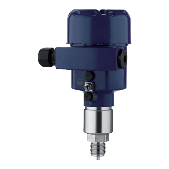
- Page 1 Operating Instructions Process pressure transmitter IPT-10 Vers. 2.0 - ceramic sensor Profibus PA Document ID: 31541...
-
Page 2: Table Of Contents
Fault rectification ......35 Process pressure transmitter IPT-10 Vers. 2.0 - ceramic sensor • Profibus PA... - Page 3 To ensure reliable setup and operation of your IPT-1* Vers. 2.0, we offer accessories and replacement parts. The corresponding docu- mentations are: Operating instructions manual "External indicating and adjustment unit" Process pressure transmitter IPT-10 Vers. 2.0 - ceramic sensor • Profibus PA...
-
Page 4: About This Document
The dot set in front indicates a list with no implied sequence. à Action This arrow indicates a single action. Sequence Numbers set in front indicate successive steps in a procedure. Process pressure transmitter IPT-10 Vers. 2.0 - ceramic sensor • Profibus PA... -
Page 5: For Your Safety
During the entire duration of use, the user is obliged to determine the compliance of the necessary occupational safety measures with the current valid rules and regulations and also take note of new regulations. Process pressure transmitter IPT-10 Vers. 2.0 - ceramic sensor • Profibus PA... -
Page 6: Safety Label On The Instrument
Please note the Ex-specific safety information for installation and operation in Ex areas. These safety instructions are part of the operating instructions manual and come with the Ex-approved instruments. Process pressure transmitter IPT-10 Vers. 2.0 - ceramic sensor • Profibus PA... -
Page 7: Product Description
Process fitting with measuring cell Type label The type label contains the most important data for identification and use of the instrument: Article number Serial number Technical data Process pressure transmitter IPT-10 Vers. 2.0 - ceramic sensor • Profibus PA... -
Page 8: Principle Of Operation
3.4 Packaging, transport and storage Packaging Your instrument was protected by packaging during transport. Its capacity to handle normal loads during transport is assured by a test according to DIN EN 24180. Process pressure transmitter IPT-10 Vers. 2.0 - ceramic sensor • Profibus PA... - Page 9 Avoiding mechanical shock and vibration Storage and transport Storage and transport temperature see chapter "Supplement - temperature Technical data - Ambient conditions" Relative humidity 20 … 85 % Process pressure transmitter IPT-10 Vers. 2.0 - ceramic sensor • Profibus PA...
-
Page 10: Mounting
The ventilation of the electronics housing as well as the atmosperic compensation pressure compensation for the measuring cell are realised via a filter element in the area of the cable gland. Process pressure transmitter IPT-10 Vers. 2.0 - ceramic sensor • Profibus PA... - Page 11 Process temperature Ambient temperature Make sure that the upper temperature limits for the environment of electronics housing and connection cable specified in chapter "Technical data" are not exceeded. Process pressure transmitter IPT-10 Vers. 2.0 - ceramic sensor • Profibus PA...
-
Page 12: Mounting Instructions
The housing must not be used to screw the instrument in! Applying tightening force can damage internal parts of the housing. Probable position correction see chapter "Setup steps". Process pressure transmitter IPT-10 Vers. 2.0 - ceramic sensor • Profibus PA... -
Page 13: Connecting To Power Supply
The total capacitance of the cable and of all capacitors must not exceed 10 nF in Ex applications. Process pressure transmitter IPT-10 Vers. 2.0 - ceramic sensor • Profibus PA... -
Page 14: Connection Procedure
Insert the wire ends into the open terminals according to the wiring plan Fig. 5: Connection steps 6 and 7 Press down the opening levers of the terminals, you will hear the terminal spring closing Process pressure transmitter IPT-10 Vers. 2.0 - ceramic sensor • Profibus PA... -
Page 15: Wiring Plan, Single Chamber Housing
Plug connector for service Spring-loaded terminals for connection of the external indicating and adjustment module Ground terminal for connection of the cable screen Spring-loaded terminals for voltage supply Process pressure transmitter IPT-10 Vers. 2.0 - ceramic sensor • Profibus PA... -
Page 16: Wiring Plan, Double Chamber Housing
5 6 7 8 Fig. 8: Electronics compartment, double chamber housing Plug connector for service Internal connection cable to the connection compartment Terminals for the external indicating and adjustment unit Process pressure transmitter IPT-10 Vers. 2.0 - ceramic sensor • Profibus PA... -
Page 17: Switch On Phase
The following steps are carried out: Internal check of the electronics Indication of the instrument type, the firmware as well as the sensor TAGs (sensor designation) Status byte goes briefly to fault value Process pressure transmitter IPT-10 Vers. 2.0 - ceramic sensor • Profibus PA... - Page 18 The values correspond to the actual measured level as well as to the set- tings already carried out, e.g. default setting. Process pressure transmitter IPT-10 Vers. 2.0 - ceramic sensor • Profibus PA...
-
Page 19: Set Up With The Indicating And Adjustment Module
Screw housing cover with inspection window tightly back on Removal is carried out in reverse order. The indicating and adjustment module is powered by the sensor, an additional connection is not necessary. Process pressure transmitter IPT-10 Vers. 2.0 - ceramic sensor • Profibus PA... - Page 20 Note: If you intend to retrofit the instrument with an indicating and adjustment module for continuous measured value indication, a higher cover with an inspection glass is required. Process pressure transmitter IPT-10 Vers. 2.0 - ceramic sensor • Profibus PA...
-
Page 21: Adjustment System
Approx. 10 minutes after the last pressing of a key, an automatic reset to measured value indication is triggered. Any values not confirmed with [OK] will not be saved. Process pressure transmitter IPT-10 Vers. 2.0 - ceramic sensor • Profibus PA... -
Page 22: Setup Steps
The actual measured value is also displayed in the menu items for min./max. adjustment. Select unit In this menu item you select the adjustment unit as well as the unit for the temperature indication in the display. Process pressure transmitter IPT-10 Vers. 2.0 - ceramic sensor • Profibus PA... - Page 23 Select the requested unit, e.g. kg/dm³ with [->] and confirm with [OK], the submenu "Density" appears. Selection options: mbar, bar, psi, Pa, kPa, MPa, inHg, mmHg, inH Process pressure transmitter IPT-10 Vers. 2.0 - ceramic sensor • Profibus PA...
- Page 24 Min. adjustment +000.0 % +0000.0 mbar 0000.0 mbar Set the requested percentage value with [+] and [->]. Edit the requested mbar value with [OK]. Selection options: °C, °F. Process pressure transmitter IPT-10 Vers. 2.0 - ceramic sensor • Profibus PA...
- Page 25 "Proc- Select application "Process pressure measurement" ess pressure measurement" Select the unit of measurement Carry out a position correction Carrying out zero adjustment Carrying out span adjustment Process pressure transmitter IPT-10 Vers. 2.0 - ceramic sensor • Profibus PA...
- Page 26 To select the adjustment unit (in the example switching over from bar to mbar), proceed as follows: Selection options: mbar, bar, psi, Pa, kPa, MPa, inHg, mmHg, inH Process pressure transmitter IPT-10 Vers. 2.0 - ceramic sensor • Profibus PA...
- Page 27 Position correction Offset +0000 mbar 53 mbar Select with [->], e.g. to accept actual measured value. Position correction Accept current measured value? ▶ Accept Edit Selection options: °C, °F. Process pressure transmitter IPT-10 Vers. 2.0 - ceramic sensor • Profibus PA...
- Page 28 (in the above example 1 bar = 1000 mbar). Set the requested mbar value with [->] and [OK]. Confirm with [OK] and move to the menu overview with [ESC]. The span adjustment is finished. Process pressure transmitter IPT-10 Vers. 2.0 - ceramic sensor • Profibus PA...
- Page 29 Menu section Function Reset value Basic settings Sensor address Zero/Min. adjustment Measuring range begin Span/Max. adjustment Measuring range end 1 kg/l Density Density unit kg/l Sensor-specific basic adjustment. Process pressure transmitter IPT-10 Vers. 2.0 - ceramic sensor • Profibus PA...
- Page 30 You will find a detailed description of these menu items in the operating instructions manual "Indicating and adjustment module". Special parameters are parameters which are set customer-specifically on the service level with the adjustment software PACTware. Process pressure transmitter IPT-10 Vers. 2.0 - ceramic sensor • Profibus PA...
-
Page 31: Menu Schematic
Basic settings Display ▶ Diagnostics Service Info 3.3.1 Peak value Sensor status Trend curve p-min.: -5.8 mbar p-max.: 167.5 mbar Start trend curve? T-min.: -12.5 °C T-max.: +85.5 °C Process pressure transmitter IPT-10 Vers. 2.0 - ceramic sensor • Profibus PA... - Page 32 Diagnostics Service ▶ Info Instrument type Calibration date Last change using PC Sensor characteristics 26. August 2010 Software version Display now? 3.82 26. August 2010 Serial number 12345678 Process pressure transmitter IPT-10 Vers. 2.0 - ceramic sensor • Profibus PA...
-
Page 33: Saving The Parameter Adjustment Data
If it is necessary to exchange the sensor, the indicating and adjustment module is inserted into the replacement instrument and the data are written into the sensor under the menu item "Copy sensor data". Process pressure transmitter IPT-10 Vers. 2.0 - ceramic sensor • Profibus PA... -
Page 34: Setup With Pdm
PDM. The instrument descriptions are already implemented in the current version of PDM. For older versions of PDM, a free-of-charge download is available via Internet. Go via www.wika.com to the item "Service". Process pressure transmitter IPT-10 Vers. 2.0 - ceramic sensor • Profibus PA... -
Page 35: Maintenance And Fault Rectification
Wrong presenta- Simatic S5 can- Insert converting component from tion of the meas- not interpret the Siemens ured value in number format Simatic S5 IEEE of the measured value Process pressure transmitter IPT-10 Vers. 2.0 - ceramic sensor • Profibus PA... - Page 36 à Carry out a software update or send instrument for repair Fault message can also appear if the pressure is higher than the nominal range. Process pressure transmitter IPT-10 Vers. 2.0 - ceramic sensor • Profibus PA...
-
Page 37: Instrument Repair
Please contact the agency serving you for the address of the return shipment By doing this you help us carry out the repair quickly and without having to call back for needed information. Process pressure transmitter IPT-10 Vers. 2.0 - ceramic sensor • Profibus PA... -
Page 38: Dismounting
9.2 Disposal Note: When disposing of old instruments, take note of the valid legal and municipal regulations. The appropriate parts must be recycled. Process pressure transmitter IPT-10 Vers. 2.0 - ceramic sensor • Profibus PA... -
Page 39: Supplement
Output signal digital output signal, format according to IEEE-754 126 (default setting) Sensor address 10 mA, ±0.5 mA Current value Dynamic behaviour output 10 s Run-up time approx. Process pressure transmitter IPT-10 Vers. 2.0 - ceramic sensor • Profibus PA... - Page 40 Adjustment range of the zero/span adjustment relating to the nominal measuring range: zero -20 … +95 % Span -120 … +120 % Values less than -1 bar cannot be set. Process pressure transmitter IPT-10 Vers. 2.0 - ceramic sensor • Profibus PA...
- Page 41 0 … 25 bar/0 … 2500 kPa 130 bar/13000 kPa 0 bar abs. 0 … 60 bar/0 … 6000 kPa 200 bar/20000 kPa 0 bar abs. Nominal measuring ranges and overload capability in psig Process pressure transmitter IPT-10 Vers. 2.0 - ceramic sensor • Profibus PA...
- Page 42 860 … 1060 mbar/86 … 106 kPa (12.5 … 15.4 psig) Air pressure Limit point adjustment according to IEC 61298-2 Determination of characteristics Characterstic curve Linear Reference installation position upright, diaphragm points downward Process pressure transmitter IPT-10 Vers. 2.0 - ceramic sensor • Profibus PA...
- Page 43 Applies also to the analogue 4 … 20 mA current output and refers to the set span. < 0.05 %/10 K, max. < 0.15 %, each with Thermal change, current output -40 … +80 °C (-40 … +176 °F) Incl. non-linearity, hysteresis and non-repeatability. Process pressure transmitter IPT-10 Vers. 2.0 - ceramic sensor • Profibus PA...
- Page 44 -30 … +120 °C (-22 … +248 °F) EPDM (A+P 75.5/KW75F) -40 … +120 °C (-40 … +248 °F) mechanical vibrations with 4 g and 5 … 150 Hz Vibration capacitance According to IEC 60098-2-6. Process pressure transmitter IPT-10 Vers. 2.0 - ceramic sensor • Profibus PA...
- Page 45 9 … 24 V DC EEx-ia instrument Operating voltage with lighted indicating and adjustment module Depending on the version M12 x 1, according to ISO 4400, Harting, 7/8" FF. Process pressure transmitter IPT-10 Vers. 2.0 - ceramic sensor • Profibus PA...
- Page 46 Instruments with gauge pressure measuring ranges cannot detect the am- bient pressure when submerged, e.g. in water. This can lead to falsification of the measured value. Process pressure transmitter IPT-10 Vers. 2.0 - ceramic sensor • Profibus PA...
-
Page 47: Information On Profibus Pa
Source for Scaling Alarms Damping mode Mode scaling PA-Out Select additional cyclic value Fig. 15: IPT-1* Vers. 2.0: Block diagram with AI (PA-OUT) value and Additional Cyclic Value Process pressure transmitter IPT-10 Vers. 2.0 - ceramic sensor • Profibus PA... - Page 48 In the following you will see how the modules can be combined and how the appendant data telegram is structured. Example 1 (standard setting) with pressure value, temperature value and additional cyclical value: Process pressure transmitter IPT-10 Vers. 2.0 - ceramic sensor • Profibus PA...
- Page 49 Additional Cyclic Value Byte-No. IEEE-754- Status IEEE-754- Status Format Floating point value Floating point value PA-OUT Status Additional Cyclic Status Value (FB1) (FB1) Value Fig. 19: Telegram configuration example 3 Process pressure transmitter IPT-10 Vers. 2.0 - ceramic sensor • Profibus PA...
- Page 50 Failsafe replacement value (Failsafe-Mode = "Last value" and already valid measured value since switching on) 0 x 48 uncertain substitute set l Switch on simulation l Failsafe replacement value (Failsafe-Mode = "Fsafe value") Process pressure transmitter IPT-10 Vers. 2.0 - ceramic sensor • Profibus PA...
- Page 51 0 x 8d good (non-cascade) - active crit- Lo-Lo-Alarm ical alarm - low limited 0 x 8e good (non-cascade) - active crit- Hi-Hi-Alarm ical alarm - high limited Process pressure transmitter IPT-10 Vers. 2.0 - ceramic sensor • Profibus PA...
- Page 52 G ½ A ½ NPT ø 3mm ") ø 6mm ") Fig. 23: IPT-1* Vers. 2.0 GD = G½ A manometer connection EN 837, ND = ½ NPT Process pressure transmitter IPT-10 Vers. 2.0 - ceramic sensor • Profibus PA...
- Page 53 10 Supplement Process pressure transmitter IPT-10 Vers. 2.0 - ceramic sensor • Profibus PA...
- Page 54 10 Supplement Process pressure transmitter IPT-10 Vers. 2.0 - ceramic sensor • Profibus PA...
- Page 55 10 Supplement Process pressure transmitter IPT-10 Vers. 2.0 - ceramic sensor • Profibus PA...
- Page 56 Printing date: WIKA Alexander Wiegand SE & Co. KG Alexander-Wiegand-Straße 30 63911 Klingenberg/Germany Phone +49 9372 132295 Fax +49 9372 132706 e-mail: support-tronic@wika.de www.wika.de All statements concerning scope of delivery, application, practical use and operating conditions of the sensors and processing systems correspond to the information avail- able at the time of printing.
Need help?
Do you have a question about the IPT-10 and is the answer not in the manual?
Questions and answers