
Related Manuals for WIKA DPT-20


Summary of Contents for WIKA DPT-20
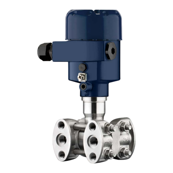
- Page 1 Operating Instructions Differential pressure transmitter DPT-20 Foundation Fieldbus Metallic measuring cell Differential pressure transmitter DPT-20...
-
Page 2: Table Of Contents
Flow measurement ......................55 Diagnosis, asset management and service ................ 57 Maintenance ........................57 Diagnosis memory ......................57 Asset Management function ................... 58 Rectify faults ........................60 Replace process flanges ....................61 WIKA Operating Instructions - Differential pressure transmitter DPT-20... - Page 3 Take note of the Ex specific safety instructions for Ex applications. These instructions are attached as documents to each instrument with Ex approval and are part of the operating instructions. Editing status: 2021-01-11 WIKA Operating Instructions - Differential pressure transmitter DPT-20...
-
Page 4: About This Document
The dot set in front indicates a list with no implied sequence. Sequence of actions Numbers set in front indicate successive steps in a procedure. Battery disposal This symbol indicates special information about the disposal of bat- teries and accumulators. WIKA Operating Instructions - Differential pressure transmitter DPT-20... -
Page 5: For Your Safety
During work on and with the device, the required personal protective equipment must always be worn. Appropriate use DPT-20 is an instrument for measurement of flow, level, differential pressure, density and interface. You can find detailed information about the area of application in chapter "... -
Page 6: Namur Recommendations
English language. Installations in the US shall comply with the relevant requirements of the National Electrical Code (ANSI/NFPA 70). Installations in Canada shall comply with the relevant requirements of the Canadian Electrical Code. WIKA Operating Instructions - Differential pressure transmitter DPT-20... -
Page 7: Product Description
Instrument type Field for approvals Technical data Product code Order number Serial number of the instrument Symbol of the device protection class ID numbers, instrument documentation Reminder to observe the instrument documentation WIKA Operating Instructions - Differential pressure transmitter DPT-20... -
Page 8: Principle Of Operation
With digital signal outputs, the static pressure is available as a separate measured value. – Fig. 3: Flow measurement with DPT-20 and orifice, Q = flow, differential pres- sure Δp = p WIKA Operating Instructions - Differential pressure transmitter DPT-20... - Page 9 The pressures in two different pipelines are acquired via effective measurement pressure lines. The device determines the differential pressure. Fig. 4: Measurement of the differential pressure in pipelines with DPT-20, dif- ferential pressure Δp = p Density measurement With the help of the instrument, density measurement in a vessel with changing level and homogeneous density distribution can be easily realized.
-
Page 10: Supplementary Cleaning Procedures
Differential pressure sensor Separating diaphragm Supplementary cleaning procedures The DPT-20 is also available in the version " Oil, grease and silicone- free". These instruments have passed through a special cleaning procedure to remove oil, grease and paint-wetting impairment sub- stances (PWIS). -
Page 11: Packaging, Transport And Storage
The overvoltage arrester is used instead of the terminals in the single or double chamber housing. Mounting accessories The suitable mounting accessories for DPT-20 include oval flange adapters, valve blocks as well as mounting brackets. WIKA Operating Instructions - Differential pressure transmitter DPT-20... - Page 12 3 Product description WIKA Operating Instructions - Differential pressure transmitter DPT-20...
-
Page 13: Mounting
This applies mainly to outdoor installations, in areas where high humidity is expected (e.g. through cleaning processes) and on cooled or heated vessels. Note: Make sure that during installation or maintenance no moisture or dirt can get inside the instrument. WIKA Operating Instructions - Differential pressure transmitter DPT-20... - Page 14 This applies especially for device versions with a plastic process connection, e.g. with G½ thread. If there is strong vibration at the mounting location, the instrument version with external housing should be used. See chapter " External housing". WIKA Operating Instructions - Differential pressure transmitter DPT-20...
-
Page 15: Instructions For Oxygen Applications
Recommendations for wiring of effective pressure lines are stated in the corresponding national and international standards. Connection Effective pressure lines are connected to the device via standard cut- ting ring screw connections with suitable thread. WIKA Operating Instructions - Differential pressure transmitter DPT-20... -
Page 16: Mounting And Connection Instructions
Mounting and connection instructions Connection high/low When connecting DPT-20 to the measuring point, take note of the pressure side high/low pressure side of the process component. The " H" identifies the high pressure side, the low pressure side due to an "... - Page 17 Breather valve 3-fold valve block, flang- ing on both sides Fig. 11: Connection of a 3-fold valve block, flanging on both sides Process fitting Process fitting Inlet valve Inlet valve Breather valve WIKA Operating Instructions - Differential pressure transmitter DPT-20...
-
Page 18: Measurement Setups
For simplification, the effective pressure lines are partly shown with a horizontal course and sharp angles. For wiring, please observe the instructions in chapter " Mounting, Connection to the process" as well WIKA Operating Instructions - Differential pressure transmitter DPT-20... - Page 19 • For measurement in products with solid content, such as e.g. dirty liquids, the installation of separators and drain valves is recom- mended. Debris and sediment can thus be collected and removed. WIKA Operating Instructions - Differential pressure transmitter DPT-20...
- Page 20 • For measurement in products with solid content, such as e.g. dirty liquids, the installation of separators and drain valves is recom- mended. Debris and sediment can thus be collected and removed. WIKA Operating Instructions - Differential pressure transmitter DPT-20...
- Page 21 In gases Fig. 17: Measurement setup with flow measurement of gases, connection via 3-fold valve block, flanging on both sides Orifice or impact pressure probe 3-fold valve block, flanging on both sides DPT-20 WIKA Operating Instructions - Differential pressure transmitter DPT-20...
- Page 22 • Fill the effective pressure lines to the height of the condensate vessels before setup WIKA Operating Instructions - Differential pressure transmitter DPT-20...
- Page 23 Pipelines Blocking valves 3-fold valve block DPT-20 • In vapour and conden- Mount device below the measurement loop so that some conden- sate plants sate can collect in the effective pressure lines. WIKA Operating Instructions - Differential pressure transmitter DPT-20...
- Page 24 Blocking valves 3-fold valve block Precipitator Drain valves DPT-20 • When chemical seal Mount chemical seal with capillaries on top or laterally on the systems are used in all pipeline products WIKA Operating Instructions - Differential pressure transmitter DPT-20...
- Page 25 4 Mounting • In vacuum applications: Mount DPT-20 below the measurement loop • The ambient temperature should be the same for both capillaries – Fig. 23: Measurement setup, differential pressure measurement in gases, vapours and liquids Chemical seal with slotted nut Capillaries E.g.
- Page 26 Δp = ρ • g • h = 1000 kg/m³ • 9.81 m/s • 0.3 m = 2943 Pa = 29.43 mbar WIKA Operating Instructions - Differential pressure transmitter DPT-20...
-
Page 27: Connecting To The Bus System
Make sure that the cable screen and grounding are carried out ac- Cable screening and grounding cording to Fieldbus specification. We recommend to connect the cable screening to ground potential on both ends. WIKA Operating Instructions - Differential pressure transmitter DPT-20... -
Page 28: Connecting
In case of flexible cores without end sleeves, press the terminal from above with a small screwdriver, the terminal opening is then free. When the screwdriver is released, the terminal closes again. WIKA Operating Instructions - Differential pressure transmitter DPT-20... -
Page 29: Wiring Plans
For external display and adjustment unit Ground terminal for connection of the cable screening 5.3.2 Double chamber housing The following illustrations apply to the non-Ex as well as to the Ex-ia version. WIKA Operating Instructions - Differential pressure transmitter DPT-20... - Page 30 Fig. 29: Connection compartment - double chamber housing Voltage supply, signal output For display and adjustment module or interface adapter For external display and adjustment unit Ground terminal for connection of the cable screening WIKA Operating Instructions - Differential pressure transmitter DPT-20...
- Page 31 5.3.4 Housing IP66/IP68 (1 bar) Wire assignment, con- nection cable Fig. 32: Wire assignment in permanently connected connection cable Brown (+) and blue (-) to power supply or to the processing system Shielding WIKA Operating Instructions - Differential pressure transmitter DPT-20...
- Page 32 Cable gland for voltage supply Cable gland for connection cable, transmitter Terminal compartment, housing socket 1 2 3 4 Fig. 34: Connection of the process component in the housing base Yellow White Black Shielding Breather capillaries WIKA Operating Instructions - Differential pressure transmitter DPT-20...
-
Page 33: Switch-On Phase
Indication of a status message on the display or PC Then the actual measured value is output to the signal cable. The value takes into account settings that have already been carried out, e.g. default setting. WIKA Operating Instructions - Differential pressure transmitter DPT-20... -
Page 34: Set Up The Sensor With The Display And Adjustment Module
The display and adjustment module is powered by the sensor, an ad- ditional connection is not necessary. Fig. 36: Installing the display and adjustment module in the electronics compart- ment of the single chamber housing WIKA Operating Instructions - Differential pressure transmitter DPT-20... -
Page 35: Adjustment System
– Move to the menu overview – Confirm selected menu – Edit parameter – Save value • [->] key: – Change measured value presentation – Select list entry – Select menu items WIKA Operating Instructions - Differential pressure transmitter DPT-20... -
Page 36: Measured Value Indication
In this menu item, you can select the national language for further parameterization. With the " [->]" button, you can select the requested language, with " OK" you confirm the selection and move to the main menu. WIKA Operating Instructions - Differential pressure transmitter DPT-20... -
Page 37: Parameter Adjustment - Quick Setup
Info: Instrument name, hardware and software version, factory cali- bration date, device ID, sensor features Note: For optimum setting of the measuring point, the individual submenu items in the main menu item " Setup" should be selected one after WIKA Operating Instructions - Differential pressure transmitter DPT-20... - Page 38 The submenu points are described below. 6.5.1 Setup Application The DPT-20 can be used for flow, differential pressure, density and interface measurement. The default setting is differential pressure measurement. Switchover is carried out in the adjustment menu. Depending on the selected application, different subchapters in the following adjustment steps are important.
- Page 39 (offset). The position correction function compensates this offset. In the process the current measured value can be accepted automatically. DPT-20 has two separate sensor systems: one sensor for differential pressure and one sensor for static pressure. The following possibili- ties thus result for position correction: •...
- Page 40 Now select with [->] the menu item " Adjustment", then " Min. adjustment" and confirm with [OK]. 2. Edit the percentage value with [OK] and set the cursor to the requested position with [->]. WIKA Operating Instructions - Differential pressure transmitter DPT-20...
- Page 41 The maximum negative pressure must then be entered for the min. adjustment. For linearization, select " bidirec- tional" or " bidirectional-extracted by root" accordingly, see menu item " Linerarization". The min. adjustment is finished. WIKA Operating Instructions - Differential pressure transmitter DPT-20...
- Page 42 1. Select with [->] the menu item Span adjustment and confirm with [OK]. 2. Edit the mbar value with [OK] and set the cursor to the requested position with [->]. WIKA Operating Instructions - Differential pressure transmitter DPT-20...
- Page 43 2. Edit the percentage value with [OK] and set the cursor to the requested position with [->]. 3. Set the requested percentage value with [+] and save with [OK]. The cursor jumps now to the density value. WIKA Operating Instructions - Differential pressure transmitter DPT-20...
- Page 44 2. Edit the percentage value with [OK] and set the cursor to the requested position with [->]. 3. Set the requested percentage value with [+] and save with [OK]. The cursor jumps now to the height value. WIKA Operating Instructions - Differential pressure transmitter DPT-20...
- Page 45 Read data from the sensor into the display and adjustment module Releasing the sensor adjustment is also possible in any menu item by entering the PIN. Caution: With active PIN, adjustment via PACTware/DTM and other systems is also blocked. WIKA Operating Instructions - Differential pressure transmitter DPT-20...
- Page 46 • Czech • Turkish In delivery status, the DPT-20 is set to English. Display value 1 and 2 - In this menu item, you define which measured value is displayed. bus systems The default setting for the displayed value is " Differential pressure".
- Page 47 Select the requested simulation variable and set the requested value. To deactivate the simulation, you have to push the [ESC] key and confirm the message " Deactivate simulation" with the [OK] key. WIKA Operating Instructions - Differential pressure transmitter DPT-20...
- Page 48 Slave for electronic differ- Deactivated ential pressure Units Unit of measurement mbar (with nominal measuring range ≤ 400 mbar) bar (with nominal measuring ranges ≥ 1 bar) Temperature unit °C Position correction 0.00 bar WIKA Operating Instructions - Differential pressure transmitter DPT-20...
- Page 49 Scaling format 0 % corresponds to 0 l 100 % corresponds to 0 l DP flow element Unit kg/s Adjustment 0 % corresponds to 0 kg/s 100 % corresponds to 1 kg/s WIKA Operating Instructions - Differential pressure transmitter DPT-20...
- Page 50 In exceptional cases, individual parameters can be modified in order to adapt the sensor to special requirements. Change the settings of the special parameters only after having con- tacted our service staff. WIKA Operating Instructions - Differential pressure transmitter DPT-20...
-
Page 51: Saving The Parameterisation Data
Saving the parameterisation data On paper We recommended writing down the adjustment data, e.g. in this op- erating instructions manual, and archiving them afterwards. They are thus available for multiple use or service purposes. WIKA Operating Instructions - Differential pressure transmitter DPT-20... - Page 52 If the instrument is equipped with a display and adjustment module, ment module the parameter adjustment data can be saved therein. The procedure is described in menu item " Copy device settings". WIKA Operating Instructions - Differential pressure transmitter DPT-20...
-
Page 53: Set Up Measuring System
Briefly open valve 6 and 7, then close again: Fill the high pressure side completely with the medium and remove air. 4. Set measurement loop to operation Now: Valve 3, 6 and 7 are closed Valves 2, 4, A and B are open WIKA Operating Instructions - Differential pressure transmitter DPT-20... - Page 54 Close valve 3: Separate high and low pressure side Open valve 4: Connect low pressure side Now: Valve 3, 6 and 7 are closed Valves 2, 4, A and B are open. WIKA Operating Instructions - Differential pressure transmitter DPT-20...
-
Page 55: Flow Measurement
Fig. 43: Preferred measurement setup for liquids DPT-20 3-fold valve block III Precipitator 1, 5 Drain valves 2, 4 Inlet valves Breather valve 6, 7 Vent valves on DPT-20 A, B Blocking valves Proceed as follows: WIKA Operating Instructions - Differential pressure transmitter DPT-20... - Page 56 Valves A and B open 6. Carry out position correction, if flow can be blocked. In this case, step 5 is not required. Arrangement with 5 valves. Valves 1, 3, 5: Configuration with 5 valves. WIKA Operating Instructions - Differential pressure transmitter DPT-20...
-
Page 57: Diagnosis, Asset Management And Service
Up to 500 events are automatically stored with a time stamp in the sensor (non-deletable). Each entry contains date/time, event type, event description and value. Event types are for example: • Modification of a parameter WIKA Operating Instructions - Differential pressure transmitter DPT-20... -
Page 58: Asset Management Function
The measurement is affected, but the measured value is still valid. Plan in maintenance for the instrument because a failure is expected in the near future (e.g. due to buildup). This status message is inactive by default. WIKA Operating Instructions - Differential pressure transmitter DPT-20... - Page 59 F265 Sensor no longer carries out a Carry out a reset Bit 11 measurement Measurement function Disconnect operating voltage disturbed briefly WIKA Operating Instructions - Differential pressure transmitter DPT-20...
-
Page 60: Rectify Faults
Error when carrying out a reset settings Rectify faults Reaction when malfunc- The operator of the system is responsible for taking suitable meas- tion occurs ures to rectify faults. Fault rectification The first measures are: WIKA Operating Instructions - Differential pressure transmitter DPT-20... -
Page 61: Replace Process Flanges
2. Mount process flanges carefully on the differential pressure measuring cell, the seal must remain in the groove 3. Insert undamaged screws and nuts, screw together crosswise 4. First tighten with 8 Nm, then with 12 Nm WIKA Operating Instructions - Differential pressure transmitter DPT-20... -
Page 62: Exchange Process Module On Version Ip68 (25 Bar)
Proceed as follows when carrying out the exchange: 1. Losen the fixing screw with the hexagon key wrench 2. Carefully detach the cable assembly from the process module Fig. 45: DPT-20 in IP68 version, 25 bar and lateral cable outlet, external housing Process module Plug connector... -
Page 63: Instrument Repair
Complete one form for each instrument • If necessary, state a contamination • Clean the instrument and pack it damage-proof • Attach the completed form and possibly also a safety data sheet to the instrument WIKA Operating Instructions - Differential pressure transmitter DPT-20... -
Page 64: Dismount
Pass the instrument directly on to a specialised recycling company and do not use the municipal collecting points. If you have no way to dispose of the old instrument properly, please contact us concerning return and disposal. WIKA Operating Instructions - Differential pressure transmitter DPT-20... -
Page 65: Supplement
A2-70, hexagon nut DIN 934 M8 A2-70 Ʋ Ground terminal 316Ti/316L Ʋ Connection between IP68 transmitter PE, PUR and external electronics housing Note deviating process temperature limits Glass with Aluminium and stainless steel precision casting housing WIKA Operating Instructions - Differential pressure transmitter DPT-20... - Page 66 0.45 psig -0.45 psig +0.45 psig 1.5 psig -1.5 psig +1.5 psig 7.5 psig -7.5 psig +7.5 psig 45 psig -45 psig -45 psig 240 psig -240 psig +240 psig 4 layers PTFE WIKA Operating Instructions - Differential pressure transmitter DPT-20...
- Page 67 Electronics temperature Current value Ʋ Non-Ex, Ex-ia and Ex-d instruments 12 mA, ±0.5 mA Dynamic behaviour output Dynamic characteristics depending on medium and temperature The specifications refer to the nominal measuring range. WIKA Operating Instructions - Differential pressure transmitter DPT-20...
- Page 68 Via the digital output signal (depending on the electron- ics version) Reference conditions and influencing variables (according to DIN EN 60770-1) Reference conditions according to DIN EN 61298-1 Ʋ Temperature +18 … +30 °C (+64 … +86 °F) WIKA Operating Instructions - Differential pressure transmitter DPT-20...
- Page 69 160 bar (16000 kPa) 500 mbar (50 kPa)/7.3 psi resp. 3 bar (300 kPa)/43.51 psi 400 bar (40000 kPa) 16 bar (1600 kPa)/232.1 psi Flow > 50 % Measuring range end, absolute pressure Root characteristic WIKA Operating Instructions - Differential pressure transmitter DPT-20...
- Page 70 < ±0.15 % + 0.15 % x TD < ±0.15 % + 0.20 % x TD Thermal change zero signal and output span, static pressure Root characteristic Relating to the adjusted span. Relating to the measuring range end value. WIKA Operating Instructions - Differential pressure transmitter DPT-20...
- Page 71 Static pressure < ±0.065 % < ±0.1 % < ±0.15 % Measuring range end, absolute pressure. Measuring range end, absolute pressure. Relating to the adjusted span. Relating to the measuring range end value. WIKA Operating Instructions - Differential pressure transmitter DPT-20...
- Page 72 4 g at 5 … 200 Hz according to EN 60068-2-6 (vibration with resonance) Shock resistance 50 g, 2.3 ms according to EN 60068-2-27 (mechanical shock) Reference temperature +25 °C (+77 °F). 2 g with housing version stainless steel double chamber WIKA Operating Instructions - Differential pressure transmitter DPT-20...
- Page 73 Ʋ Colour - version PUR Blue Connection cable, electrical data Ʋ Wire cross-section 0.5 mm² (AWG 20) Ʋ Wire resistance R 0.037 Ω/m (0.012 Ω/ft) ´ IP66/IP68 (0.2 bar), only with absolute pressure. WIKA Operating Instructions - Differential pressure transmitter DPT-20...
- Page 74 Shielded 4 … 20 mA/HART 50 m ● – Modbus Profibus PA, Foundation Fieldbus 25 m – ● Integrated clock Date format Day.Month.Year Time format 12 h/24 h Time zone, factory setting WIKA Operating Instructions - Differential pressure transmitter DPT-20...
- Page 75 Type 6P Stainless steel Transmitter, version with exter- IP68 (25 bar) nal housing Galvanic separation between electronics and metal housing parts Protection rating IP66/IP68 (0.2 bar) only in conjunction with absolute pressure. WIKA Operating Instructions - Differential pressure transmitter DPT-20...
-
Page 76: Device Communication Foundation Fieldbus
Polarity Insensitive Max. Current Load 11 mA Device minimum operating voltage Transmitter Function Blocks Resource Block (RB) Transducer Block (TB) Standard Block (AI) Execution Time 30 mS When used with fulfilled housing protection. WIKA Operating Instructions - Differential pressure transmitter DPT-20... -
Page 77: Calculation Of The Total Deviation
: Thermal change of zero signal and output span (temperature error) • : Deviation • : Thermal change of the current output • FMZ: Additional factor measuring cell version • FTD: Additional factor Turn down WIKA Operating Instructions - Differential pressure transmitter DPT-20... -
Page 78: Calculation Of The Total Deviation - Practical Example
Time range Measured variable 1 year 5 years 10 years Differential pressure < 0.065 % x TD < 0.1 % x TD < 0.15 % x TD Relating to the adjusted span. WIKA Operating Instructions - Differential pressure transmitter DPT-20... -
Page 79: Dimensions, Versions Process Component
~ 84 mm (3.31") (2.72") ø 77 mm ø 84 mm (3.03") (3.31") M16x1,5 M20x1,5/ ½ NPT M20x1,5/ ½ NPT Plastic single chamber Plastic double chamber Relating to the measuring range end value. WIKA Operating Instructions - Differential pressure transmitter DPT-20... - Page 80 ø 77 mm (3.31") (3.15") (3.03") M16x1,5 M20x1,5/ ½ NPT M20x1,5/ M20x1,5/ ½ NPT ½ NPT Stainless steel single chamber (electropolished) Stainless steel single chamber (precision casting) Stainless steel double chamber housing (precision casting) WIKA Operating Instructions - Differential pressure transmitter DPT-20...
- Page 81 ø 84 mm (3.03") (3.31") (3.31") M16x1,5 M20x1,5 M20x1,5 M20x1,5 M20x1,5/ ½ NPT Aluminium - single chamber Stainless steel single chamber (precision casting) Aluminium double chamber housing, stainless steel double chamber housing (precision casting) WIKA Operating Instructions - Differential pressure transmitter DPT-20...
- Page 82 ~ 66 mm (2.6") ø 41,6 mm (1.64") 110 mm x 90 mm (4.33" x 3.54") Fig. 47: External housing Lateral cable outlet Cable outlet axial Plastic single chamber Stainless steel single chamber WIKA Operating Instructions - Differential pressure transmitter DPT-20...
- Page 83 Fig. 49: DPT-20, lateral ventialtion Connection Fastening Material Scope of delivery ¼-18 NPT, IEC 61518 7/16-20 UNF 316L incl. 4 closing screws and 2 ventilation valves 316L ¼-18 NPT, IEC 61518 7/16-20 UNF Alloy C276 (2.4819) WIKA Operating Instructions - Differential pressure transmitter DPT-20...
- Page 84 86,1 mm 86,1 mm (3.39") (3.39") Fig. 50: left: Process fitting DPT-20 prepared for chemical seal assembly. right: Position of the copper ring seal Chemical seal connection Copper ring seal Separating diaphragm WIKA Operating Instructions - Differential pressure transmitter DPT-20...
-
Page 85: Trademark
10 Supplement 10.6 Trademark All the brands as well as trade and company names used are property of their lawful proprietor/ originator. WIKA Operating Instructions - Differential pressure transmitter DPT-20... - Page 86 Notes WIKA Operating Instructions - Differential pressure transmitter DPT-20...
- Page 87 Notes WIKA Operating Instructions - Differential pressure transmitter DPT-20...
- Page 88 All statements concerning scope of delivery, application, practi- cal use and operating conditions of the sensors and processing systems correspond to the information available at the time of printing. WIKA Alexander Wiegand SE & Co. KG Alexander-Wiegand-Straße 30 63911 Klingenberg Germany...
Need help?
Do you have a question about the DPT-20 and is the answer not in the manual?
Questions and answers