Advertisement
Table of Contents
- 1 Table of Contents
- 2 General Information
- 3 Design and Function
- 4 Safety
- 5 Transport, Packaging and Storage
- 6 Commissioning, Operation
- 7 Connection Diagram
- 8 Modbus ® Version
- 9 Maintenance, Cleaning and Recalibration
- 10 Dismounting, Return and Disposal
- 11 Specifications
- 12 Accessories
- Download this manual
Advertisement
Table of Contents

Subscribe to Our Youtube Channel
Related Manuals for WIKA air2guide A2G-50


Summary of Contents for WIKA air2guide A2G-50
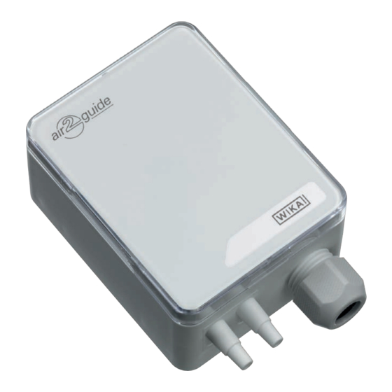
- Page 1 Operating instructions Betriebsanleitung Differential pressure transmitter, model A2G-50 Model A2G-50...
- Page 2 Operating instructions model A2G-50 Page 3 - 34 © 01/2009 WIKA Alexander Wiegand SE & Co. KG All rights reserved. / Alle Rechte vorbehalten. WIKA is a registered trademark in various countries. ® WIKA ist eine geschützte Marke in verschiedenen Ländern.
-
Page 3: Table Of Contents
4. Transport, packaging and storage 5. Commissioning, operation 6. Modbus version ® 7. Maintenance, cleaning and recalibration 8. Dismounting, return and disposal 9. Specifications 10. Accessories Declarations of conformity can be found online at www.wika.com. WIKA operating instructions model A2G-50... -
Page 4: General Information
The general terms and conditions contained in the sales ■ documentation shall apply. Subject to technical modifications. ■ Further information: ■ - Internet address: www.wika.de / www.wika.com www.air2guide.com - Relevant data sheet: PE 88.02 WIKA operating instructions model A2G-50... -
Page 5: Design And Function
Electrical analogue output signals for both measurands (0 ... 10 V or 4 ... 20 mA; adjustable in the instrument via jumpers) or the digital Modbus versions enable the direct connection to control systems or the ® building automation system. WIKA operating instructions model A2G-50... -
Page 6: Safety
2 x 2 m PVC measuring hose (option) ■ Cross-check scope of delivery with delivery note. 3. Safety 3.1 Explanation of symbols WARNING! ... indicates a potentially dangerous situation that can result in serious injury or death, if not avoided. WIKA operating instructions model A2G-50... - Page 7 This instrument is not permitted to be used in hazardous areas! The instrument has been designed and built solely for the intended use described here, and may only be used accordingly. WIKA operating instructions model A2G-50...
- Page 8 Improper handling or operation of the instrument outside of its technical specifications requires the instrument to be taken out of service immediately and inspected by an authorised WIKA service engineer. The manufacturer shall not be liable for claims of any type based on operation contrary to the intended use.
- Page 9 The personnel trained by the operator are understood to be personnel who, based on their education, knowledge and experience, are capable of carrying out the work described and independently recognising potential hazards. Special operating conditions require further appropriate knowledge, e.g. of aggressive media. WIKA operating instructions model A2G-50...
- Page 10 Supply: DC 24 V / AC 24 V ±10 % < 1 W E-Nr. 66209848 Made in EU Model Measuring range Output signal Power supply Serial number Before mounting and commissioning the instrument, ensure you read the operating instructions! WIKA operating instructions model A2G-50...
-
Page 11: Transport, Packaging And Storage
Avoid exposure to the following factors: Direct sunlight or proximity to hot objects ■ Mechanical vibration, mechanical shock (putting it down hard) ■ Soot, vapour, humidity, dust and corrosive gases ■ Hazardous environments, flammable atmospheres ■ WIKA operating instructions model A2G-50... -
Page 12: Commissioning, Operation
Damage to the instrument When working on open electrical circuits (printed circuit boards) there is a risk of damaging sensitive electronic components through electrostatic discharge. ▶ The correct use of grounded working surfaces and personal armbands is required. WIKA operating instructions model A2G-50... - Page 13 2. Opening the instrument cover, feeding the connection cable through the cable gland and connecting the wires to the terminal block (see chapter 5.2 “Electrical mounting”) 3. The instrument is now ready for configuration (see chapter 5.3 “Configuration”) WIKA operating instructions model A2G-50...
- Page 14 1. Select a mounting location (duct, wall, panel). 2. Remove the case cover and use the screw holes as a template. 3. Mount with suitable screws. Instrument fixing Instrument orientation WIKA operating instructions model A2G-50...
- Page 15 5. Commissioning, operation Application-related connections Static pressure Filter Ventilator measurement monitoring monitoring WIKA operating instructions model A2G-50...
-
Page 16: Connection Diagram
24 V Power supply AC/DC 24 V Pressure P Signal [U] 100 % 10.0 V 50 % 5.0 V 0.0 V Time axis t [s] Pressure P Signal [I] 100 % 20.0 mA WIKA operating instructions model A2G-50... - Page 17 4. Select the desired response time (see chapter 5.6). 5. Carry out a zero point setting (see chapter 5.7). 6. Connect measurement hoses. (overpressure = connection “+”, vacuum = connection “-”) 7. Close the cover. The instrument is now ready for operation. WIKA operating instructions model A2G-50...
- Page 18 3. Remove the jumper from J5 in order to select the desired unit which should be shown on the display. Installing the jumpers (Dark grey colour indicates the jumper placement) No jumper Jumper installed Storing the Circuit open Circuit closed jumper WIKA operating instructions model A2G-50...
- Page 19 0 ... 5.0 0 ... 50.0 0 ... 20.00 0 ... 510.0 0 ... 0.7250 0 ... 7,000 0 ... 7.0 0 ... 70.0 0 ... 28.00 0 ... 714.0 0 ... 1.0150 MB = measuring range WIKA operating instructions model A2G-50...
- Page 20 Jumper placement to set the measuring range Range 1 Range 2 Range 3 Range 4 Jumper J1 Jumper J2 Jumper J3 Range 5 Range 6 Range 7 Range 8 Jumper J1 Jumper J2 Jumper J3 WIKA operating instructions model A2G-50...
- Page 21 In order to change the response time, install or remove a jumper in slot J4. Jumper in slot J4 - 4.0 seconds response time. ■ No jumper in slot J4 = 0.8 seconds response time ■ WIKA operating instructions model A2G-50...
- Page 22 During the zero point setting the display and output value remains at the last measured value. The automatic zero point setting takes 3 seconds and is repeated every 10 minutes. ZERO WIKA operating instructions model A2G-50...
-
Page 23: Modbus ® Version
“ADDRESS” selection. ▶ “ADDRESS” menu item flashes Use “UP” or “DOWN” to find the desired Modbus ® address. ADDRESS ▶ Selection is displayed. Move the “SELECT” button once, shortly, in order to ADDRESS accept the selection. WIKA operating instructions model A2G-50... - Page 24 “BAUD RATE” menu item flashes Use “UP” or “DOWN” to find the desired baud rate. ▶ Selection is displayed BAUD RATE 19200 Move the “SELECT” button once, shortly, in order to accept the selection. BAUD RATE 19200 WIKA operating instructions model A2G-50...
- Page 25 “PARITY BIT” menu item flashes Use “UP” or “DOWN” to find the desired parity bit. ▶ Selection is displayed PARITY BIT EVEN Move the “SELECT” button once, shortly, in order to accept the selection. PARITY BIT EVEN WIKA operating instructions model A2G-50...
- Page 26 Use “UP” or “DOWN” to find the desired pressure unit. ▶ PRESS.UNIT Selection is displayed inchWC Move the “SELECT” button once, shortly, in order to accept the selection. PRESS.UNIT inchWC 6. Press the “SELECT” button in order to exit the menu. SELECT EXIT MENU WIKA operating instructions model A2G-50...
-
Page 27: Maintenance, Cleaning And Recalibration
2. Use the requisite protective equipment. 3. Clean the instrument with a moist cloth (soapy water). Electrical connections must not come into contact with moisture! WIKA operating instructions model A2G-50... -
Page 28: Dismounting, Return And Disposal
▶ Observe the information in the material safety data sheet for the corresponding medium. ▶ Wash or clean the dismounted instrument, in order to protect persons and the environment from exposure to residual media. WIKA operating instructions model A2G-50... - Page 29 Upon contact with live parts, there is a direct danger to life. ▶ The dismounting of the instrument may only be carried out by skilled personnel. ▶ Remove the differential pressure transmitter once the system has been isolated from power sources. WIKA operating instructions model A2G-50...
- Page 30 8.2 Return Strictly observe the following when shipping the instrument: All instruments delivered to WIKA must be free from any kind of hazardous substances (acids, bases, solutions, etc.) and must therefore be cleaned before being returned.
-
Page 31: Specifications
(AZ), digital display and automatic zero point setting (AZ-D) ±1.5 % +1 Pa Accuracy (of measured pressure) Units (adjustable in the menu) Air flow /h, m /s, l/s, cfm ■ Differential pressure Pa, kPa, mbar, inWC, mmWC ■ WIKA operating instructions model A2G-50... - Page 32 Baud rate 9,600, 19,200, 38,400 - adjustable in the configuration Modbus addresses 1 ... 247 addresses - adjustable in the configuration ® For further specifications see WIKA data sheet PE 88.02 and the order documentation. WIKA operating instructions model A2G-50...
-
Page 33: Accessories
PVC hose, inner diameter 6 mm, roll at 25 m 40217850 Silicone hose, inner diameter 4 mm, roll at 25 m 40208940 Silicone hose, inner diameter 6 mm, roll at 25 m 40208958 Duct connector for hose 4 and 6 mm 40217507 WIKA operating instructions model A2G-50...
Need help?
Do you have a question about the air2guide A2G-50 and is the answer not in the manual?
Questions and answers