Table of Contents
Advertisement
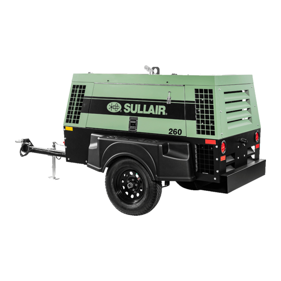
AIR COMPRESSOR
185H, 210H, 260 CFM
CATERPILLAR & JOHN DEERE
PORTABLE
OPERATOR'S
MANUAL AND
PARTS LIST
KEEP FOR
FUTURE
REFERENCE
Part Number
02250156---375
Sullair Corporation
The information in this document is
correct at the time of printing for
Portable Compressor Serial Number
004 150300
and all subsequent Serial Numbers.
Advertisement
Table of Contents

Related Manuals for Sullair 260 CFM


Summarization of Contents
Section 1 SAFETY
1.1 GENERAL
General safety precautions for operating Sullair compressors.
1.2 TOWING
Procedures and warnings for towing the compressor safely.
1.3 PRESSURE RELEASE
Instructions for relieving pressure and using flow-limiting valves.
1.4 FIRE AND EXPLOSION
Precautions to prevent fires and explosions during operation and maintenance.
1.5 MOVING PARTS
Warnings about keeping clear of moving parts and wearing appropriate clothing.
1.6 HOT SURFACES, SHARP EDGES AND SHARP CORNERS
Precautions for hot surfaces, sharp edges, and first aid.
1.7 TOXIC AND IRRITATING SUBSTANCES
Handling toxic substances and ventilation requirements.
1.8 ELECTRICAL SHOCK
Safety measures for electrical hazards and proximity to power lines.
1.9 LIFTING
Safe procedures and precautions for lifting the compressor using appropriate equipment.
1.10 ENTRAPMENT
Safety measures to prevent entrapment when closing enclosure doors.
1.11 JUMP STARTING
Detailed instructions and warnings for safely jump-starting the compressor.
Section 2 DESCRIPTION
2.1 INTRODUCTION
Overview of Sullair compressors, their features and benefits.
2.2 DESCRIPTION OF COMPONENTS
Detailed identification of major components and their functions.
2.3 SULLAIR COMPRESSOR UNIT, FUNCTIONAL DESCRIPTION
Explanation of the rotary screw compressor unit's internal workings.
2.4 COMPRESSOR COOLING AND LUBRICATION SYSTEM, FUNCTIONAL DESCRIPTION
How the cooling and lubrication system maintains optimal performance.
2.5 COMPRESSOR DISCHARGE SYSTEM, FUNCTIONAL DESCRIPTION
How compressed air and fluid are separated and managed.
2.6 CAPACITY CONTROL SYSTEM, FUNCTIONAL DESCRIPTION
Explanation of how the system regulates air output based on demand.
2.7 AIR INLET SYSTEM, FUNCTIONAL DESCRIPTION
Details of the air intake system, including filters.
2.8 INSTRUMENT PANEL GROUP, FUNCTIONAL DESCRIPTION
Explanation of the gauges, switches, and indicators on the control panel.
2.9 ELECTRICAL SYSTEM, FUNCTIONAL DESCRIPTION
Overview of the electrical system and safety shutdown features.
2.10 SHUTDOWN SYSTEM DESCRIPTION
How the shutdown system monitors and reacts to malfunctions.
Section 3 SPECIFICATIONS
3.1A SPECIFICATIONS -- JOHN DEERE
Technical specifications for John Deere engine models.
3.1B SPECIFICATIONS -- CATERPILLAR
Technical specifications for Caterpillar engine models.
3.2 LUBRICATION GUIDE -- COMPRESSOR
Recommended fluids and change intervals for the compressor.
3.3 APPLICATION GUIDE
Guidance on fluid selection based on operating conditions.
3.4 LUBRICATION GUIDE -- ENGINE
Engine oil specifications are found in the Operator's Manual.
Section 4 OPERATION
4.1 GENERAL
Importance of understanding controls and indicators for proper operation.
4.2 PURPOSE OF CONTROLS
Explains the function of each control and indicator on the instrument panel.
4.3 START--UP PROCEDURE
Step-by-step guide for initiating compressor operation.
4.4 SUBSEQUENT START--UP PROCEDURE
Steps for starting the compressor after initial use.
4.5 SHUTDOWN PROCEDURE
Correct procedure for safely stopping the compressor.
Section 5 MAINTENANCE
5.1 GENERAL
Importance of a good maintenance program for compressor longevity.
5.2 DAILY OPERATION
Daily checks required before starting the compressor.
5.3 MAINTENANCE AFTER INITIAL 50 HOURS OF OPERATION
Initial maintenance tasks to remove foreign materials.
5.3A MAINTENANCE EVERY 50 HOURS
Routine maintenance tasks performed every 50 operating hours.
5.4 MAINTENANCE EVERY 100 HOURS
Maintenance tasks required every 100 operating hours.
5.5 MAINTENANCE EVERY 250 HOURS
Key maintenance tasks performed every 250 operating hours.
5.6A MAINTENANCE EVERY 1500 HOURS OR ANNUALLY
Significant maintenance tasks done every 1500 hours or annually.
5.6B MAINTENANCE EVERY YEAR OR 12,000 MILES
Annual maintenance for wheel-mounted units.
5.7 PARTS REPLACEMENT AND ADJUSTMENT PROCEDURES
Detailed procedures for replacing parts and making adjustments.
5.8 TROUBLESHOOTING -- INTRODUCTION
Introduction to the troubleshooting guide, its basis, and analysis approach.
5.9 TROUBLESHOOTING GUIDE
A guide to diagnosing and resolving common compressor symptoms.
Section 6 NOISE CONTROL
6.1 NOISE EMISSIONS WARRANTY
Sullair's warranty regarding noise emissions compliance.
6.2 TAMPERING WITH THE NOISE CONTROL SYSTEM IS PROHIBITED
Federal law prohibits tampering with noise control devices.
6.3 NOISE EMISSIONS MAINTENANCE AND MAINTENANCE RECORD LOG
Instructions for maintaining noise control systems and logging maintenance.
Section 7 ILLUSTRATIONS AND PARTS LIST
7.1 PROCEDURE FOR ORDERING PARTS
Instructions on how to order replacement parts from Sullair.
7.2 RECOMMENDED SPARE PARTS LIST
A list of recommended spare parts for common maintenance needs.
7.3A ENGINE, COMPRESSOR & PARTS -- 185H & 210H CATERPILLAR
Illustrated parts breakdown for Caterpillar engines on 185H/210H models.
7.3B ENGINE, COMPRESSOR & PARTS -- 260 CATERPILLAR
Illustrated parts breakdown for Caterpillar engines on 260 models.
7.3C ENGINE, COMPRESSOR & PARTS -- 185H & 210H JOHN DEERE
Illustrated parts breakdown for John Deere engines on 185H/210H models.
7.3D ENGINE, COMPRESSOR & PARTS -- 260 JOHN DEERE
Illustrated parts breakdown for John Deere engines on 260 models.
7.4A AIR INLET AND EXHAUST -- ALL CATERPILLAR MODELS
Illustrated parts for air inlet and exhaust systems on Caterpillar models.
7.4B AIR INLET AND EXHAUST -- ALL JOHN DEERE MODELS
Illustrated parts for air inlet and exhaust systems on John Deere models.
7.5 AIR INLET VALVE ASSEMBLY -- 260 JOHN DEERE AND CATERPILLAR
Illustrated parts for the air inlet valve assembly.
7.6 RADIATOR & COMPRESSOR FLUID COOLING SYSTEM -- ALL MODELS
Illustrated parts for the cooling system.
7.7A FRAME, RUNNING GEAR & PARTS -- ALL MODELS
Illustrated parts for the frame and running gear.
7.7B FRAME LESS RUNNING GEAR & PARTS -- ALL MODELS
Illustrated parts for the frame without running gear.
7.8 DISCHARGE SYSTEM AND PARTS -- ALL MODELS
Illustrated parts for the discharge system.
7.9A REGULATOR VALVE/BLOWDOWN VALVE ASSEMBLY -- ALL 185H & 210H MODELS
Illustrated parts for the regulator/blowdown valve assembly.
7.9B REGULATOR VALVE/BLOWDOWN VALVE ASSEMBLY -- ALL 260 MODELS
Illustrated parts for the regulator/blowdown valve assembly.
7.10 ELECTRICAL PARTS -- ALL MODELS
Illustrated parts for the electrical system.
7.11A FUEL TANK AND PARTS -- ALL CATERPILLAR MODELS
Illustrated parts for the fuel tank system on Caterpillar models.
7.11B FUEL TANK AND PARTS -- ALL JOHN DEERE MODELS
Illustrated parts for the fuel tank system on John Deere models.
7.12 CANOPY, ACOUSTICAL PANELS & PARTS -- ALL MODELS
Illustrated parts for the canopy and acoustical panels.
7.13 INSTRUMENT PANEL & PARTS -- ALL MODELS
Illustrated parts for the instrument panel.
7.14A INSTRUMENT PANEL AND PARTS -- 185H AND 210H CATERPILLAR (STANDARD GAUGE)
Parts for the standard gauge instrument panel on Caterpillar 185H/210H.
7.14B INSTRUMENT PANEL AND PARTS -- 260 CATERPILLAR (STANDARD GAUGE)
Parts for the standard gauge instrument panel on Caterpillar 260.
7.14C INSTRUMENT PANEL AND PARTS -- 185H AND 210H JOHN DEERE (STANDARD GAUGE)
Parts for the standard gauge instrument panel on John Deere 185H/210H.
7.14D INSTRUMENT PANEL AND PARTS -- 260 JOHN DEERE (STANDARD GAUGE)
Parts for the standard gauge instrument panel on John Deere 260.
7.14E INSTRUMENT PANEL AND PARTS -- 185H AND 210H CATERPILLAR (FULL GAUGE)
Parts for the full gauge instrument panel on Caterpillar 185H/210H.
7.14F INSTRUMENT PANEL AND PARTS -- 260 CATERPILLAR (FULL GAUGE)
Parts for the full gauge instrument panel on Caterpillar 260.
7.14G INSTRUMENT PANEL AND PARTS -- 185H AND 210H JOHN DEERE (FULL GAUGE)
Parts for the full gauge instrument panel on John Deere 185H/210H.
7.14H INSTRUMENT PANEL AND PARTS -- 260 JOHN DEERE (FULL GAUGE)
Parts for the full gauge instrument panel on John Deere 260.
7.15 SINGLE HOSE REEL OPTION -- ALL MODELS
Illustrated parts for the single hose reel option.
7.16 DUAL HOSE REEL OPTION -- ALL MODELS
Illustrated parts for the dual hose reel option.
7.17 ONE PINT OILER OPTION -- ALL MODELS
Illustrated parts for the one pint oiler option.
7.18 ONE QUART OILER / MOISTURE SEPARATOR OPTIONS -- ALL MODELS
Illustrated parts for oiler/moisture separator options.
7.19 CANADIAN TAIL / CLEARANCE LIGHTS -- ALL MODELS
Illustrated parts for Canadian lighting requirements.
7.20 DECALS
Illustrations and descriptions of various decals on the compressor.
7.21 DECAL LOCATIONS
Diagrams showing the placement of decals on the compressor.
7.22 DRAWBAR INSTALLATION -- ALL MODELS
Instructions and parts for drawbar installation.
Need help?
Do you have a question about the 260 CFM and is the answer not in the manual?
Questions and answers