
Related Manuals for Sullair 20/12 Series


Summary of Contents for Sullair 20/12 Series
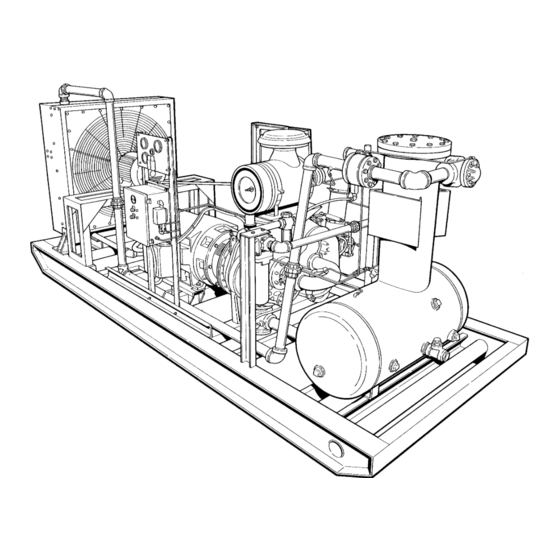
- Page 1 Operator’s Manual and Parts List 20/12 200-400HP (Air-Cooled) Industrial Rotary Screw Air Compressor Part Number 253497 eSullair Corporation...
- Page 2 AIR CARE SEMINAR TRAINING Sullair Air Care Seminars are 3--day courses that provide hands--on instruction in the proper operation, maintenance and service of Sullair equipment. Individual seminars on Industrial compressors and compressor electrical systems are presented at regular intervals throughout the year at a dedicated training facility at Sullair’s corporate headquarters in Michigan City, Indiana.
-
Page 3: Table Of Contents
1.8 ELECTRICAL SHOCK 1.9 LIFTING 1.10 ENTRAPMENT Section 2 DESCRIPTION 2.1 INTRODUCTION 2.2 DESCRIPTION OF COMPONENTS 2.3 SULLAIR COMPRESSOR UNIT, FUNCTIONAL DESCRIPTION 2.4 COMPRESSOR COOLING AND LUBRICATION SYSTEM, FUNCTIONAL DESCRIPTION 2.5 COMPRESSOR DISCHARGE SYSTEM, FUNCTIONAL DESCRIPTION 2.6 CAPACITY CONTROL SYSTEM, FUNCTIONAL DESCRIPTION 2.7 AIR INLET SYSTEM, FUNCTIONAL DESCRIPTION... - Page 4 TABLE OF CONTENTS (CONTINUED) Section 6 MAINTENANCE 6.1 GENERAL 6.2 DAILY OPERATION 6.3 MAINTENANCE AFTER INITIAL 50 HOURS OF OPERATION 6.4 MAINTENANCE AS REQUIRED BY LUBRICATION GUIDE (SECTION 3) 6.5 FILTER MAINTENANCE 6.6 PARTS REPLACEMENT AND ADJUSTMENT PROCEDURES SEPARATOR MAINTENANCE SERVICING THE BEARING FLUID FILTER AIR FILTER MAINTENANCE SERVICING THE MAIN FLUID FILTER...
-
Page 5: General
1.1 GENERAL failure, OSHA Standard Sullair Corporation and its subsidiaries design and 1926.302(b)(7). manufacture all of its products so they can be oper- B. When the hose is to be used to supply a manifold, ated safely. However, the responsibility for safe op-... -
Page 6: Moving Parts
Section 1 SAFETY on any external surfaces of the air compressor or on E. Make sure all personnel are out of and/or clear of internal surfaces of the enclosure. Wipe down using the compressor prior to attempting to start or oper- an aqueous industrial cleaner or steam clean as re- ate it. -
Page 7: Electrical Shock
Section 1 SAFETY G. If air line anti--icer system antifreeze compound slings instead. In any event, lift and/or handle only in enters the eyes or if fumes irritate the eyes, they full compliance with OSHA standards 29 CFR 1910 should be washed with large quantities of clean wa- subpart N. -
Page 8: Entrapment
Section 1 SAFETY 1.10 ENTRAPMENT A. If the compressor enclosure, if any, is large enough to hold a man and if it is necessary to enter it to perform service adjustments, inform other per- sonnel before doing so, or else secure and tag the access door in the open position to avoid the possi- bility of others closing and possibly latching the door with personnel inside. -
Page 9: Introduction
Sullair is unique in mechanical reliability, with virtually no wear or loss of perfor- The 2--stage Sullair compressor unit is driven by an mance. With a Sullair compressor, there is no in- industrial motor designed to provide enough horse-... -
Page 10: Sullair Compressor Unit, Functional Description
This filter has a cleanable element and built--in bypass which allow some fluid to flow 2.3 SULLAIR COMPRESSOR UNIT, FUNCTIONAL even when the filter becomes plugged and requires DESCRIPTION changing, or when the viscosity of the fluid is too The compressor unit supplied with your compressor high for adequate flow. - Page 11 265_F (130_C) on second stage. A check valve is also provided to prevent air in the All Sullair compressor models are equipped with a service line from bleeding back into the sump at high pressure shutdown switch to shut down the...
- Page 12 Section 2 DESCRIPTION Figure 2-3 Piping and Instrumentation...
-
Page 13: Capacity Control System, Functional Description
Section 2 DESCRIPTION Figure 2-4 Compressor Discharge System (Typical) parallel with other compressors tied to a large sys- scription will apply to compressors with an operating tem. It is recommended that an optional gate--type pressure range of 340 to 360 PSIG (2344 to service valve be used downstream of the check 2482kPa). - Page 14 Section 2 DESCRIPTION Figure 2-5 Capacity Control System (Typical)
- Page 15 Section 2 DESCRIPTION Figure 2-6 Control System MODULATING MODE - - 340 TO 360 PSIG (2344 plied directly to the Sullicon Control keeping the but- TO 2482kPa) terfly valve closed. Simultaneously, the pilot valve If less than the rated capacity of compressed air is sends a pneumatic signal to the blowdown valve.
-
Page 16: Air Inlet System, Functional Description
Section 2 DESCRIPTION check valve and continually monitors the air pres- Figure 2-7 Air Inlet System (Typical) sure. S The sump pressure gauge continually monitors the sump pressure at the various load and/or unload conditions. S The discharge temperature gauge monitors the temperature of the air leaving the compressor unit. -
Page 17: Lubrication Guide
Operator’s manual. WARRANTIES. Sullube 32 fluid should be changed every 1800 Sullair encourages the user to participate in a fluid hours or once a year, whichever comes first. The analysis program with the fluid suppliers. This could... - Page 18 NOTES...
-
Page 19: Mounting Of Compressor
1. A s hut -- off v alv e s hould be ins t alled t o plicable local electrical code concerning isolation isolate the compressor from the service line if re- switches, fused disconnects, etc. Sullair provides a quired. Also notice that the service line should be wiring diagram for use by the installer. - Page 20 NOTES...
-
Page 21: General
OPERATION 5.1 GENERAL for service or indicate the beginning of a malfunc- While Sullair has built into this compressor a com- tion. Before starting your Sullair compressor, read prehensive array of controls and indicators to as- this section thoroughly and familiarize yourself with... - Page 22 Section 5 OPERATION 5.2 PURPOSE OF CONTROLS CONTROL OR INDICATOR PURPOSE PRESSURE RELIEF VALVE (Sump) Opens sump pressure to the atmosphere should pres- sure inside the sump become too high (375 PSIG [2584kPa]). PRESSURE RELIEF VALVE (Interstage) Opens inner stage to atmosphere should the pressure become too high (140 PSIG [965kPa]).
-
Page 23: Initial Start- -Up Procedure
Section 5 OPERATION 5.3 INITIAL START- -UP PROCEDURE NOTE The following procedure should be used to make the initial start--up of the compressor: High inlet air temperatures will result in high dis- 1. Read the preceding pages of this manual thor- charge air temperatures. - Page 24 NOTES...
-
Page 25: General
Stop compressor and relieve all internal pressure To assist with the removal of the tank lid, Sullair has provided a 1”- - 8 nut to the top lid so it can be before doing so. -
Page 26: Servicing The Bearing Fluid Filter
Section 6 MAINTENANCE 5. Scrape the old gasket material from the tank lid Figure 6-2 Bearing Filter (P/N 250019-296) mounting surface and the flanges mounting sur- face on the tank. Be sure to keep all scrapings from falling back inside of the tank. 6. -
Page 27: Servicing The Main Fluid Filter
Section 6 MAINTENANCE Figure 6-3 Air Filter 750 CFM 800- -960CFM 500- -630 CFM 046956 046020 048456 Filter Part Number Element Repair Kit Part Number (primary) 046968 046299 048462 Element Repair Kit Part Number (secondary) 047523 046981 048463 8. Install the new secondary element and replace the 2. -
Page 28: Control System Adjustment
Section 6 MAINTENANCE sure switch contacts should open. If the pressure Figure 6-4 Main Fluid Filter (P/N 045111) switch contacts do not open or they open prior to the des ir ed pr es s ur e, t he pr es s ur e s wit c h s et t ing will r e- quir e adjus t m ent ( r ef er t o F igur e 6 -- 5) . -
Page 29: Pressure Regulator Valve Maintenance
Section 6 MAINTENANCE 7. The next step is to reassemble the regulator using Figure 6-6 Sullicon Control (P/N 011682-003) the new parts provided in the repair kit. 8. Reassemble the diaphragm, pressure plate, dia- phragm gasket, seat disc and seat disc gasket and tighten the nut. -
Page 30: Fluid Stop Valve
Section 6 MAINTENANCE 1. Loosen the locknut and turn the adjusting screw the exception of the pressure plate are provided in counterclockwise until the inner spring tension is the repair kit. relieved. The adjusting screw should turn freely 11. Replace the pusher post o--ring with the new one when the spring tension is relieved. -
Page 31: Running Blowdown Valve Maintenance
Section 6 MAINTENANCE Figure 6-9 Fluid Stop Valve (P/N 250038-489) NOTE Cylinder is chamfered on one end. Install from this side. 19. Install the two (2) seals; one into the cover and the other onto the piston rod guide. 20. Place cylinder over pilot guide. 21. -
Page 32: Thermal Valve
Section 6 MAINTENANCE 3. Remove and discard the old o--ring on the poppet Figure 6-11 Thermal Valve (P/N 250001-456) guide and replace it with the new o--ring provided in the kit. Be sure to lubricate the o--ring with a sili- cone base lubricant such as Parker Super “O”... -
Page 33: Pilot Valve Maintenance
Section 6 MAINTENANCE the components of the compressor are cool to the 8. Reset piston assembly into the main body and re- touch. position spring and flat washer. 9. Replace retaining cap. 1. Unscrew the minimum pressure/check valve (P/N 10. Reattach valve to receiver cover and reconnect all 018498A) from the receiver cover. - Page 34 Section 6 MAINTENANCE Figure 6-13 Pilot Valve (P/N 407390) * Repair Kit P/N 042246 5. Remove end cap, end cap gasket and slip core/ 2. Lubricate all gaskets with Dow Corning’s Valve spring assembly (A--C Construction) or core (D--C Seal silicone lubricant or equivalent high grade sil- Construction) off the end of the valve lever and lift icone grease.
-
Page 35: Troubleshooting
Should your problem persist after making the recom- by placing the two springs on the shaft of a screwdriv- mended check, consult your nearest Sullair repre- er or similar tool and compressing them. The spring sentative or the Sullair Corporation factory. - Page 36 Section 6 MAINTENANCE TROUBLESHOOTING (CONTINUED) SYMPTOM PROBABLE CAUSE REMEDY COMPRESSOR SHUTS DOWN WITH AIR DEMAND PRESENT (cont.) Defective blowdown valve; blowdown valve should exhaust sump pressure to the atmosphere when maximum operating pressure is reached. Discharge Temperature Thermistor Switch Open Cooling air flow restricted;...
- Page 37 Section 6 MAINTENANCE TROUBLESHOOTING (CONTINUED) SYMPTOM PROBABLE CAUSE REMEDY LINE PRESSURE RISES ABOVE CUT- -OUT PRESSURE SETTING ON PRESSURE SWITCH (cont.) Defective Blowdown Valve Check that sump pressure is exhausted to the atmosphere when the pressure switch contacts close or repair or replace if necessary (kit available).
- Page 38 NOTES...
-
Page 39: Procedure For Ordering Parts
7.1 PROCEDURE FOR ORDERING PARTS Parts should be ordered from the nearest Sullair Representative or the Representative from whom the com- pressor was purchased. If for any reason parts cannot be obtained in this manner, contact the factory directly at the address below. -
Page 40: Motor, Frame, Compressor And Parts
Section 7 ILLUSTRATIONS AND PARTS LIST 7.3 MOTOR, FRAME, COMPRESSOR AND PARTS... - Page 41 026974 compressor unit (I) (I) There is an exchange program whereby a remanufactured compressor unit can be obtained from Sullair distributors or the factory at less cost than the owner could repair the unit. For information regarding the unit exchange program, contact your nearest Sullair representative or the Sullair Corporation.
-
Page 42: Air Inlet System
Section 7 ILLUSTRATIONS AND PARTS LIST 7.4 AIR INLET SYSTEM... - Page 43 Section 7 ILLUSTRATIONS AND PARTS LIST 7.4 AIR INLET SYSTEM part number description number quantity gasket, 81/2” x 101/2” x 1/32” 040422 valve, butterfly 8” (500--750 CFM) 040336 S valve, butterfly 8” (800--960 CFM) 040338 lever, inlet valve 250026--787 adapter, air inlet (500--750 CFM) 012897 S adapter, air inlet (800--960 CFM) 250001--083...
-
Page 44: Cooling And Lubrication System
Section 7 ILLUSTRATIONS AND PARTS LIST 7.5 COOLING AND LUBRICATION SYSTEM... - Page 45 Section 7 ILLUSTRATIONS AND PARTS LIST 7.5 COOLING AND LUBRICATION SYSTEM part number description number quantity elbow, reducing 2” x 11/2” 806808--150 nipple, pipe 2” x close 822232--000 cooler, fluid (200HP thru 300HP) 048085 S cooler, fluid (350HP thru 400HP) 408368 u--bolt, 3/8”...
-
Page 46: Cooler Assembly
Section 7 ILLUSTRATIONS AND PARTS LIST 7.6 COOLER ASSEMBLY... - Page 47 Section 7 ILLUSTRATIONS AND PARTS LIST 7.6 COOLER ASSEMBLY part number description number quantity support, cooler 250020--736 cooler, fluid (200HP thru 300HP) 048085 S cooler, fluid (350HP thru 400HP) 408368 panel, top/bottom 250020--738 panel, cooler side -- left hand 250020--740 bracket, cooler -- left hand 250021--004 S bracket, cooler -- right hand...
-
Page 48: Discharge System
Section 7 ILLUSTRATIONS AND PARTS LIST 7.7 DISCHARGE SYSTEM... - Page 49 Section 7 ILLUSTRATIONS AND PARTS LIST 7.7 DISCHARGE SYSTEM part number description number quantity element, separator (I) 409805--006 valve, relief 1” 245766 valve, minimum press 100PSIG (689kPa) (II) 018498A elbow, tube--m 1/4” x 1/4” 810504--025 tubing, steel 1/4” (ft.) 841115--004 20 feet valve, check 21/2”...
- Page 50 Section 7 ILLUSTRATIONS AND PARTS LIST 7.7 DISCHARGE SYSTEM...
- Page 51 Section 7 ILLUSTRATIONS AND PARTS LIST 7.7 DISCHARGE SYSTEM (continued) part number description number quantity support, water separator 250000--844 separator, water 406746 trap, separator 016586 elbow, pipe 45_ 3/4” 806430--030 union, pipe 3/4” 805730--030 trap, auto 3/4” 250006--639 connector, tube--m 1/4” x 1/4” 810204--025 glass, sight 046559...
-
Page 52: Instrument Panel And Parts
Section 7 ILLUSTRATIONS AND PARTS LIST 7.8 INSTRUMENT PANEL AND PARTS... - Page 53 7.8 INSTRUMENT PANEL AND PARTS part number description number quantity gauge, vacuum 250003--797 gauge, temperature 045858 gauge, pressure 048061 nameplate, Sullair 250035--063 indicator 046551 indicator, differential pressure 042148 fastener, suregrip 041516 nameplate, Sullair 040052 capscrew, hex gr5 3/8”--16 x 11/2” 828606--150 washer, springlock 3/8”...
-
Page 54: Control System
Section 7 ILLUSTRATIONS AND PARTS LIST 7.9 CONTROL SYSTEM... - Page 55 Section 7 ILLUSTRATIONS AND PARTS LIST 7.9 CONTROL SYSTEM part number description number quantity gauge, pressure 2” 250005--185 elbow, tube--m 1/4” x 1/4” 810504--025 tubing, steel 1/4” (ft.) 841015--004 25 feet orifice, pipe plug 1/4” 232874 cross, pipe 1/4” 806330--010 nipple, pipe 1/4”...
- Page 56 Section 7 ILLUSTRATIONS AND PARTS LIST 7.9 CONTROL SYSTEM...
- Page 57 Section 7 ILLUSTRATIONS AND PARTS LIST 7.9 CONTROL SYSTEM (continued) part number description number quantity screw, machine hex 5/16” -- 24 x 2” 831105--200 screw, machine shoulder 3/8”--16 x 2” 830506--200 body, control 021635 pin, cotter 1/16” x 3/4” 827101--075 yoke, rod end 1/4”--28 040138 pin, yoke 1/4”...
-
Page 58: Electric Control Box
Section 7 ILLUSTRATIONS AND PARTS LIST 7.10 ELECTRIC CONTROL BOX... - Page 59 Section 7 ILLUSTRATIONS AND PARTS LIST 7.10 ELECTRIC CONTROL BOX part number description number quantity hourmeter, 21/2” 042988 gasket, hourmeter 410353 holder, lamp 043383 S lens, green 043385 S bulb 043386 S gasket, lamp holder 241808 S gasket, lens 241809 holder, lamp 043383 S lens, red...
-
Page 60: Unit Tubing
Section 7 ILLUSTRATIONS AND PARTS LIST 7.11 UNIT TUBING... - Page 61 Section 7 ILLUSTRATIONS AND PARTS LIST 7.11 UNIT TUBING part number description number quantity plug, pipe 1/2” 807800--020 manifold, bearing 227238 elbow, hose--m 1/2” x 1/2” 860208--050 elbow, hose--m 5/8” x 1/2” 860210--050 connector, hose 3/8” x 1/2” 860106--050 hose, hydraulic 1/2” x 32” 249608--008 hose, hydraulic 5/8”...
- Page 62 Section 7 ILLUSTRATIONS AND PARTS LIST 7.11 UNIT TUBING...
- Page 63 Section 7 ILLUSTRATIONS AND PARTS LIST 7.11 UNIT TUBING (continued) part number description number quantity gasket, air inlet 028078 adapter, air inlet 013410 capscrew, ferry head gr8 3/4” x 11/2” 828412--150 coupling, flexible 31/2” 040356 gasket, flexible 040771 plug, pipe 1” 807800--040 gasket, air outlet 028077...
-
Page 64: Decal Group
Section 7 ILLUSTRATIONS AND PARTS LIST 7.12 DECAL GROUP... - Page 65 Section 7 ILLUSTRATIONS AND PARTS LIST 7.12 DECAL GROUP part number description number quantity sign, warning sever fan 049855 sign, warning sever fan port 049965 sign, danger electrocution 049850 decal, rotation 250021--286 decal, 460 volt 040631 decal, grounding lug 045433 decal, compressor fluid Sullube 32 250023--361 decal, fluid stop valve P/N 016742...
- Page 66 WORLDWIDE SALES AND SERVICE SULLAIR ASIA, LTD. SULLAIR EUROPE, S.A. Sullair Road, No. 1 Zone Des Granges BP 82 Chiwan, Shekou 42602 Montbrison Cedex, France Shenzhen, Guangdong PRV. Telephone: 33- -477968470 PRC POST CODE 518068 Fax: 33- -477968499 Telephone: 755- -6851686...
Need help?
Do you have a question about the 20/12 Series and is the answer not in the manual?
Questions and answers