Table of Contents
Advertisement
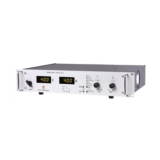
DELTA ELEKTRONIKA B.V.
DC POWER SUPPLIES
SM3000-se ries
SM 15 - 200 D
•
SM 30 - 100 D
•
SM 45 - 70 D
•
SM 70 - 45 D
•
SM 120 - 25 D
•
SM 300 - 10 D
•
PROD UCT MAN UAL
Con tents:
1 - Datasheet
2 - Safety Instructions
3 - Descriptions
4 - Operating,Trouble Shooting, Calibration
5 - EC Declaration of Conformity
Vissersdijk 4, 4301 ND
www.DeltaPowerSupplies.com
Zierikzee, the Netherlands
Tel. +31 111 413656
Advertisement
Table of Contents

Related Manuals for Delta Elektronika SM30-100D


Summarization of Contents
SAFETY INSTRUCTIONS
Caution
Basic safety warning to observe precautions during operation, service, and repair.
Installation Category
Specifies the power supply has been evaluated to installation category II.
Grounding of Mains Terminals (AC Power Terminals)
Requirement for safety Class 1 unit to be grounded via mains through a four-conductor cable.
Grounding of DC Power Terminals
Guidelines for grounding DC power terminals and sense connections to ensure safety isolation.
Danger of electrical shock
Warning about touching live contacts directly after disconnecting from the mains.
Connection to mains supply
How to connect the unit to the mains supply permanently or via an industrial type plug.
Fuses
Fuses must be replaced by authorized Delta Elektronika service personnel only.
AC Input Ratings
Do not exceed the specified AC input voltage and frequency ratings of the unit.
Live Circuits
Operating personnel should not remove covers or replace components without authorization.
Parts Substitutions & Modifications
Only authorized Delta Elektronika service personnel can perform substitutions or modifications.
Removal of (safety) covers
Procedure for safely removing safety covers, including waiting for capacitor discharge.
Environmental Conditions
Specifies operating conditions: ambient temperature, relative humidity, altitude, and pollution degree.
Correct Disposal of this Product
Instructions for responsible recycling of waste electrical equipment (WEEE) in the European Union.
DESCRIPTIONS
OUTPUT
Unit can operate as a constant voltage source with current limiting or CC source with voltage limiting.
DISPLAY CV/CC SETTING FUNCTION
Front panel meters show CV/CC setting by pressing a button, allowing limit setting.
OVERLOAD PROTECTION
Power supply is fully protected against all overload conditions, including short circuit.
INPUT VOLTAGE
Power supplies have a wide input voltage range and can operate on single phase or as DC/DC converters.
INPUT CURRENT
Discusses input current characteristics and shows figures relating output current to input voltage.
STANDBY INPUT POWER
Unit consumes very little power in standby, allowing remote shutdown of output.
EFFICIENCY
High efficiency means low power loss and low heat generation, constant over a wide output range.
REGULATION
Load regulation should be measured directly on output terminals to account for cable drop.
RIPPLE & NOISE
Output ripple is very low with almost no spikes; requires specific measurement technique.
PROGRAMMING INPUTS
Output voltage and current can be programmed by an external analog voltage (0-5V).
IEEE488 / RS232 PROGRAMMING
Voltage and current can be programmed and read back using external interface modules.
MONITORING OUTPUTS
Monitor outputs provide 0-5V proportional to output current or voltage.
STATUS OUTPUTS
Status outputs have 5V open output, 10mA short circuit current, usable for driving opto-couplers.
REMOTE SHUTDOWN
+5V on Remote ShutDown input switches off the power circuit of the unit.
PROGRAMMING SPEED
Response time depends on load; fast programming option available for quicker response.
PROGRAMMING BANDWIDTH
Bandwidth is 50 Hz for small signals; limited by output capacitors for large signals.
RECOVERY TIME
Shows recovery time for SM30-100D after a 50-100% load step.
NOISE SUPPRESSION (input / output)
Input/output have RFI filters for low conducted RFI; output is very clean.
PULSATING LOAD
AC component of load current should be limited to avoid capacitor overheating.
INSULATION
Insulation between input and output is tested at 3750 Vrms for safety.
RFI SUPPRESSION
Input and output have RFI filters for low conducted RFI, resulting in a clean output.
OPERATING TEMP
Specifies operating temperature range (-20 to +50°C) and derating above 50°C.
THERMAL PROTECTION
Thermal switch shuts down output in case of insufficient cooling; unit restarts after cooling.
HOLD - UP TIME
Hold-up time depends on load, output voltage, and line input voltage.
TURN ON DELAY
Output voltage is available 0.5 sec after mains switch on.
INRUSH CURRENT
Inrush current is limited by a 90 Ohm resistor for smooth switch on.
PHASE LOSS
Unit operates on one phase at 90% of max. output voltage with slightly higher ripple.
SERIES OPERATION
Connecting units in series using special adapters for extended voltage range up to 600V.
PARALLEL OPERATION
Connecting units in parallel for increased current capacity without limitations.
MASTER / SLAVE OPERATION
Master/Slave feature allows building larger units and centralized programming.
REMOTE SENSING
Keeps voltage constant at the load by compensating for lead voltage drops.
OVP
Protect circuits from unwanted high output voltages by limiting the voltage.
POTENTIOMETERS
CV, CC, and OVP adjustments are made via front panel knobs or screwdriver adjustments.
COOLING
A low noise blower cools the unit, with speed dependent on heatsink temperature.
DIMENSIONS
Provides physical dimensions of the power supply unit.
CIRCUIT DESCRIPTION
Explains the internal circuit, including RFI filters, inrush current limiter, and switching frequency.
OPERATING MANUAL
OPERATING THE UNIT FOR THE FIRST TIME
Guide for initial unit setup, including checks, connections, and basic settings.
ANALOG PROGRAMMING
How to program voltage and current using external analog voltage sources.
IEEE488 / RS232 PROGRAMMING
How to program and read back settings using digital communication interfaces.
MONITORING OUTPUTS
Describes how monitoring outputs provide voltage signals proportional to output parameters.
STATUS OUTPUTS
Status outputs provide signals indicating various operational states of the unit.
REMOTE SENSING
Method to keep load voltage constant by compensating for lead voltage drops.
BATTERY CHARGER
Power supplies are ideal for battery charging, providing constant voltage without overcharging.
REMOTE SHUTDOWN / OVER CURRENT TRIP
How to use Remote ShutDown input for output control and over current trip.
MASTER / SLAVE SERIES OPERATION
Connecting units in series using special adapters for extended voltage range up to 600V.
MASTER / SLAVE PARALLEL OPERATION
Connecting units in parallel for increased current capacity.
PARALLEL OPERATION OF FAST PROGRAMMING VERSIONS
Notes on parallel operation for fast programming versions, recommending testing.
MASTER / SLAVE MIXED SERIES / PARALLEL OPERATION
Using adapters for complex mixed series-parallel configurations.
OPERATING AND STORAGE CONDITIONS
TEMPERATURE
Specifies operating temperature range (-20 to +50°C) and storage range (-40 to +85°C).
HUMIDITY
Discusses humidity effects and precautions against condensation inside the unit.
GALVANIC INDUSTRY
Recommendations for using power supplies in aggressive environments like the galvanic industry.
TROUBLE SHOOTING
GENERAL
How to get assistance or arrange for repairs, including RMA form and fault description.
NO OUTPUT (normal operation)
Checks for no output condition, including fuses, switches, connections, and potentiometers.
PROGRAMMING DOES NOT WORK OK
Troubleshooting programming errors, checking programming switches and fuses.
PROGRAMMING OFFSETS
Identifies earth loops as a cause for programming offsets and suggests solutions.
STATUS OUTPUTS FAIL
Checks fuses related to status outputs and checks for blown fuses.
MASTER / SLAVE PARALLEL PROBLEMS
Troubleshooting parallel Master/Slave issues, including fuse checks and connection settings.
OUTPUT VOLTAGE IS HIGHER THAN SET VALUE
Checks SENSE BLOCK connections for correct links or sensing wiring.
OVP LED on.
Checks OVP setting, overheating, and remote sensing for OVP LED activation.
NO LEDS on.
Checks for overheating, input power, and input fuses when no LEDs are on.
CHECK POINTS IN CASE OF A SERIOUS FAILURE
Flowchart for diagnosing serious failures, checking fuses and output diodes.
CALIBRATION
GENERAL
Power supplies are factory calibrated and usually need no further calibration.
METER CALIBRATION
Describes calibration of digital meters using specific potentiometers.
CALIBRATING MAX. CURRENT RANGE or CALIBRATING CC MONITOR FULL SCALE.
Calibrating the maximum output current using R686.
CALIBRATING THE CC MONITOR OFF-SET.
Calibrating the CC monitor offset voltage using R652.
SPARE PARTS
Information on how to order spare parts, specifying model and component details.
EC DECLARATION
EC Declaration of Conformity - SM3000-series
Declares compliance with EMC and Low Voltage Directives according to specified standards.
Need help?
Do you have a question about the SM30-100D and is the answer not in the manual?
Questions and answers