Table of Contents
Advertisement
Quick Links
Advertisement
Table of Contents

Related Manuals for Vertiv DCE E24611


Summary of Contents for Vertiv DCE E24611
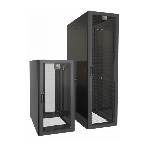
- Page 1 DCE™ Rack System Installer/User Guide...
- Page 2 Technical Support Site If you encounter any installation or operational issues with your product, check the pertinent section of this manual to see if the issue can be resolved by following outlined procedures. For additional assistance, visit https://www.VertivCo.com/en-us/support/...
-
Page 3: Table Of Contents
4.8 Vertical Airflow Baffle with Brush Kit for 700-mm W Rack: E487014/E427014/E457014 4.9 Vertical-airflow Baffle with Brush Kit and Vertical Cable Manager 4.10 Switch Kit for Side-to-side Cisco Switch for 1000-mm W Rack: E7009014/E7018014 4.11 Switch Kit for Side-to-side Cisco Switch for 800-mm W Rack: E650304/E6506014/E9513014/E6513014 4.12 Baying Gasket Kit: E4013 4.13 Baying Kit: E9013 Vertiv | DCE Installer/User Guide |... - Page 4 Vertiv | DCE Installer/User Guide |...
-
Page 5: Important Safety Instructions
WARNING: Proper spacing is required when installing electrical equipment to avoid electrical shock. Maintain minimum spacing between the accessories and components and the computer rack assembly for safe operation of the equipment when installed in accordance with the National Electric Code ANSI/NFPA 70-1999. Vertiv | DCE Installer/User Guide |... - Page 6 This page intentionally left blank. Vertiv | DCE Installer/User Guide |...
-
Page 7: What's Included
E45811 1100 E45812 1200 E45112 1000 1200 E48611 1100 E48612 1200 E48711 1100 E48712 1200 E48811 1100 E48812 1200 E48112 1000 1200 DCE static weight capacity: 3000 lbs. DCE dynamic weight capacity: 2500 lbs. Vertiv | DCE Installer/User Guide |... - Page 8 This page intentionally left blank. Vertiv | DCE Installer/User Guide |...
-
Page 9: Installation
Remove the Phillips-head bolt from the swing-handle retainer on the inside of the door. 2. Tilt the handle outward and lift up to remove it from the door. 3. Remove the Phillips-head cam retaining bolt, rotate the cam 180° and re-install cam retaining bolt. Vertiv | DCE Installer/User Guide |... - Page 10 4. After reversing the door, reinstall the swing handle by sliding downward into door and tilting inward. 5. Re-install swing-handle retainer and Phillips head bolt. Figure 3.1 Door handle components ITEM DESCRIPTION Phillips-head bolt Phillips-head cam-retaining bolt Retainer Vertiv | DCE Installer/User Guide |...
-
Page 11: Door Removal And Attachment
2. Carefully pull the door away from the rack to detach the door. 3. To attach the door, align the hinges and slide hinge pins back into the hinge assembly. Figure 3.2 Removing and Attaching door Vertiv | DCE Installer/User Guide |... -
Page 12: Field-Reversible Front And Rear Doors
Then rotate the door 180° and slide the hinge pins into the assembly. • When the door is reversed the handle must also be rotated 180°; see "Reversing the door handle" on page 9. Figure 3.3 Moving hinges to reverse doors ITEM DESCRIPTION M6 Torx screw Vertiv | DCE Installer/User Guide |... -
Page 13: Side Panel Removal
2. Lift the top panel out or off. There are 3 top panel options for DCE Racks. Figure 3.4 Removing the top panel and top-panel options ITEM DESCRIPTION Edge grommet on cut-outs M4 Torx screw Vertiv | DCE Installer/User Guide |... -
Page 14: Top Panel Mounting For The E426112Dr
Trough Washer (2 per trough Acorn nut (2 per trough) Trough flange M6 Flat-head Torx screws (6 per top) Top cover Front of rack Trough in top compartment (side panels not shown for clarity) Vertiv | DCE Installer/User Guide |... -
Page 15: Bottom Panel Mounting For The E426112Dr
Figure 3.6 Removing the bottom panel of the E426112DR ITEM DESCRIPTION Flat washer (2 per trough) Acorn nut (2 per trough) Carriage bolt (2 per trough)_ Left-side half of bottom cover M8 Hex-head bolt (2 per half of bottom cover) Vertiv | DCE Installer/User Guide |... -
Page 16: Casters And Leveling Feet
7.5 ft-lb. 4. The shorter side of the caster assembly aligns with a hole on the front of the frame. Secure with a M8 Bolt and tighten to 18 ft-lb. Vertiv | DCE Installer/User Guide |... - Page 17 Figure 3.7 Installing swivel casters on front of rack ITEM DESCRIPTION Swivel caster assembly M8 keps nut M8 pem studs Side of frame Leveling foot Front of rack M8 bolt M6 nut M6 carriage bolt Vertiv | DCE Installer/User Guide |...
- Page 18 Secure with M8 keps nut and tighten to 18 ft-lb. 7. The flange of the caster assembly aligns with a hole on the side of the frame. Secure with a M6 carriage bolt and nut and tighten to 7.5 ft-lb. Vertiv | DCE Installer/User Guide |...
- Page 19 Align the holes on the end of the support beam with the M8 pem studs on the caster assembly. • Using a 13-mm socket, secure with M8 keps nut and tighten to 18 ft-lb. Figure 3.9 Installing fixed casters on rear of rack ITEM DESCRIPTION Fixed caster assembly Rear of rack Vertiv | DCE Installer/User Guide |...
-
Page 20: Leveling Feet Adjustment
Rails are attached using an M6 carriage bolt and M6 keps nut. Loosen the top, bottom and middle bolts using a 10-mm drive socket. 2. Adjust the rails from any location from front to back. Vertiv | DCE Installer/User Guide |... - Page 21 Figure 3.11 Rail features and hardware ITEM DESCRIPTION Vertical mounting rail Lobster-claw holes Cable pass-through cut-outs Cable tie-down slots Accessory mounting holes (AMH) M6 carriage bolt M6 keps nut Locking tab Front-to-rear rack horizontal Horizontal depth marking Vertiv | DCE Installer/User Guide |...
-
Page 22: Pdu/Cable-Management Brackets
PDU, each piece of equipment should be connected to a dedicated branch circuit. Figure 3.12 Installing PDU/cable-management racks ITEM DESCRIPTION Depth measurements Key-hole cut-outs Hole pattern for D rings, lobster claws, etc. M6 keps nut M6 screw Vertiv | DCE Installer/User Guide |... -
Page 23: Optional Accessories
To install adapter brackets and cable manager on a 600-mm rack: Align the bent tabs to the cut-out pattern on the outside surface of the EIA rail, and insert them. 2. Install each adapter bracket with (14) panel fasteners. Vertiv | DCE Installer/User Guide |... - Page 24 Top-view of AMH adapter bracket Vertical cable manager installation 7 RU vertical cable manager AMH bracket AMH bracket Push fasteners for AMH bracket EIA rail M6 Torx screw Vertical cable manager Adapter bracket Push fastener for AMH bracket Vertiv | DCE Installer/User Guide |...
-
Page 25: Horizontal Front-To-Rear Cable Manager: E11015/E12015
3. Proceed to install trough into rack by finding the cut outs with (2) holes directly below cut-out. 4. From inside of rack and between rails, lift trough and engage tab through cut-out and drop into place Vertiv | DCE Installer/User Guide |... -
Page 26: Adjustable Ladder-Rack Bracket: Elrb016
Height can be adjusted to accommodate the difference in height between racks. There are many mounting holes in the top panel to accommodate the placement of the brackets. Two brackets are recommended per rack. Vertiv | DCE Installer/User Guide |... - Page 27 M6 Hex-head bolt M6 cage nut Square holes for M6 cage nuts 5/16-18 Hex nut 5/16 flat washer 1/4-20 carriage bolt Adjust top section to final height before tightening carriage bolts and hex nuts. Vertiv | DCE Installer/User Guide |...
-
Page 28: Overhead Cable Trough: E6016/7016/8016
2. Insert a cage nut into the appropriate square hole on the top panel, and secure the trough on top with M6 screws. Figure 4.5 Installing overhead cable trough ITEM DESCRIPTION M6 cage nuts and screws Vertiv | DCE Installer/User Guide |... -
Page 29: Exhaust Chimney: E1832014/E3246014
The vertical airflow baffle with brush kit is used to prevent air recirculation within the rack. It can be installed in 42, 45, and 48 RU racks that are 800-mm wide. The kit installs using the accessory mounting holes (AMH) along the rail. Vertiv | DCE Installer/User Guide |... - Page 30 Tool-less rivets for 1/4-in. push holes Brush grommet strips RU break-off intervals on brush-strip mounting plate for 45 RU and 42 RU racks Top view of brush grommet installed. EIA rail Brush grommet Brush-strip mounting plate Vertiv | DCE Installer/User Guide |...
-
Page 31: Vertical Airflow Baffle With Brush Kit For 700-Mm W Rack: E487014/E427014/E457014
Tool-less rivets for 1/4-in. push holes Brush grommet strips RU break-off intervals on brush-strip mounting plate for 45 RU and 42 RU racks Top view of brush grommet installed. EIA rail Brush grommet Brush-strip mounting plate Vertiv | DCE Installer/User Guide |... -
Page 32: Vertical-Airflow Baffle With Brush Kit And Vertical Cable Manager
AMH. Insert a tool-less rivet through both the vertical cable manager and mounting plate. Figure 4.9 Installing a baffle and cable manager together ITEM DESCRIPTION Tool-less rivets for 1/4-in. push holes AMH along EIA rail Vertical brush-mounting plate Vertiv | DCE Installer/User Guide |... -
Page 33: Switch Kit For Side-To-Side Cisco Switch For 1000-Mm W Rack: E7009014/E7018014
NOTE: For clarity, the main rack is not shown in the figure. Figure 4.10 Air-flow through the Switch Kit ITEM DESCRIPTION Cool-air intake Hot-air exhaust Left-rear EIA rail Foam gasket Vertiv | DCE Installer/User Guide |... - Page 34 5. Peel the backing from the foam gasket, and stick it in place on the top and bottom flanges of the baffle. You may need to cut the gasket to size. Figure 4.11 Fastening the baffle to the rail ITEM DESCRIPTION EIA rail gusset M6 carriage bolt Vertiv | DCE Installer/User Guide |...
- Page 35 • 6 openings on the right front and left rear of a 25 RU baffle • 3 openings on the right front and left rear of a 14 RU baffle Vertiv | DCE Installer/User Guide |...
-
Page 36: Switch Kit For Side-To-Side Cisco Switch For 800-Mm W Rack: E650304/E6506014/E9513014/E6513014
2. Assemble and adjust the baffles before mounting on the rail. 3. Peel the backing from the gasket, and stick it on the top and bottom flanges that make contact with the side of the equipment. Vertiv | DCE Installer/User Guide |... - Page 37 Figure 4.14 Switch baffle installation for 800-mm rack ITEM DESCRIPTION Exhaust baffle Gasket Tab in square-hole pattern on rail Carriage bolt in square-hole pattern on rail Intake baffle M6 wing nut M6 carriage bolt Vertiv | DCE Installer/User Guide |...
-
Page 38: Baying Gasket Kit: E4013
2. peel adhesive backing from the gasket, and place the gasket around side perimeter of one of the racks. 3. Position the racks next to each other with the gasket between them. The racks are ready for baying. Figure 4.15 Baying gasket location Vertiv | DCE Installer/User Guide |... -
Page 39: Baying Kit: E9013
3. Install 2 brackets at front and 2 at rear per the rack's mating planes, as shown in the figure. Figure 4.16 Installing baying brackets ITEM DESCRIPTION Baying bracket M6 flat-head Torx screw Screw hole for 24-in. centers Screw hole for 600-mm centers Vertiv | DCE Installer/User Guide |... - Page 40 This page intentionally left blank. Vertiv | DCE Installer/User Guide |...
- Page 42 VertivCo.com | Vertiv Headquarters, 1050 Dearborn Drive, Columbus, OH, 43085, USA © 2017 Vertiv Co. All rights reserved. Vertiv and the Vertiv logo are trademarks or registered trademarks of Vertiv Co. All other names and logos referred to are trade names, trademarks or registered trademarks of their respective owners. While every precaution has been taken to ensure accuracy and completeness herein, Vertiv Co.
Need help?
Do you have a question about the DCE E24611 and is the answer not in the manual?
Questions and answers