
Related Manuals for Rosemount 1151GP


Summary of Contents for Rosemount 1151GP
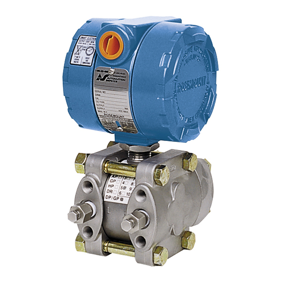
- Page 1 Reference Manual 00809-0100-4360, Rev BA August 2008 Rosemount 1151 Pressure Transmitter www.rosemount.com...
- Page 3 Using non-nuclear qualified products in applications that require nuclear-qualified hardware or products may cause inaccurate readings. For information on Rosemount nuclear-qualified products, contact your local Emerson Process Management Sales Representative. May be protected by one or more of the following U.S. Patent Nos. 4,804,958; 4,866,435;...
-
Page 5: Table Of Contents
Reference Manual 00809-0100-4360, Rev BA Rosemount 1151 August 2008 Table of Contents SECTION 1 Using This Manual ........1-1 Models Covered . - Page 6 Reference Manual 00809-0100-4360, Rev BA Rosemount 1151 August 2008 SECTION 4 Overview ..........4-1 Safety Messages .
- Page 7 Reference Manual 00809-0100-4360, Rev BA Rosemount 1151 August 2008 APPENDIX A Performance Specifications ....... . . A-1 Functional Specifications .
- Page 8 Reference Manual 00809-0100-4360, Rev BA Rosemount 1151 August 2008 TOC-4...
-
Page 9: Using This Manual
This section provides troubleshooting techniques for the most common operating problems. Section 6–Retrofitting the Rosemount 1151 Transmitter This section describes how the Rosemount Smart Retrofit Kit can be used to retrofit a Rosemount 1151AP, DP, GP, HP, or LT transmitter with 4-20 mA linear or square root output. -
Page 10: Models Covered
August 2008 MODELS COVERED This manual provides basic installation, commissioning, and troubleshooting information for the following Rosemount 1151 Pressure Transmitters: Rosemount 1151DP—Differential Pressure Transmitter Measures differential pressure up to 1,000 psi (6895 kPa). Rosemount 1151HP—Differential Pressure Transmitter for High Line Pressures Provides high line pressure up to 300 psi (2068 kPa). -
Page 11: Overview
Installation Options ......page 2-21 OVERVIEW This section is designed to guide you through a successful Rosemount 1151 installation. This section contains an installation flow chart; safety messages;... -
Page 12: Safety Messages
Reference Manual 00809-0100-4360, Rev BA Rosemount 1151 August 2008 Figure 2-1. Rosemount 1151 Installation Flowchart. Bench Calibration? START HERE START HERE START HERE Analog Analog Analog Smart Smart Smart Analog Analog Analog Using a Using a Using a FIELD FIELD... - Page 13 40 ft-lb (54 N-m) of torque. This will maintain five full threads of engagement. • When adding a meter option to a Rosemount 1151 with an Option Code R1 terminal block, make sure to change to cemented meter covers with a glass window. Make sure a sticker is located inside the cover that indicates a “cemented cover.”...
-
Page 14: General Considerations
Reference Manual 00809-0100-4360, Rev BA Rosemount 1151 August 2008 GENERAL The accuracy of a flow, pressure, or level measurement depends on proper installation of the transmitter and impulse piping. The piping between the CONSIDERATIONS process and transmitter must accurately transmit process pressure to the transmitter. - Page 15 Exterior of Electronics Housing The Rosemount 1151 Smart Pressure Transmitter uses the same housing as the Rosemount 1151 Analog. For this reason, integral span and zero screws—non-functional on the Rosemount 1151 Smart Pressure...
-
Page 16: Mechanical Considerations
Reference Manual 00809-0100-4360, Rev BA Rosemount 1151 August 2008 MECHANICAL CONSIDERATIONS Dimensional Drawings Figure 2-2. Rosemount 7.5 (191) Max. 0.75 (19) with Optional Meter ½–14 NPT 1151AP, DP, GP, and HP Clearance for Conduit Dimensional Drawings. Cover Removal Connection (Typical) 4.5 (114) - Page 17 Reference Manual 00809-0100-4360, Rev BA Rosemount 1151 August 2008 Figure 2-3. Rosemount 1151LT Dimensional Drawing. 11.38 (289) Max. (25) Serrated Face Gasket Surface Permanent Tag (optional) (114) Max. Flushing Connection Wired-on Tag (standard) OPTIONAL FLUSHING 4.45 2-, 4-, or 6-in.
-
Page 18: Mounting Considerations
Rosemount 1151 August 2008 MOUNTING The Rosemount 1151 Pressure Transmitter weighs 12 lb. (5.4 kg) without a meter and 15 lb. (6.8 kg) with a meter. This weight must be securely CONSIDERATIONS supported. The transmitter is calibrated in an upright position at the factory. If this orientation is changed during mounting, the zero point will shift by an amount equivalent to the liquid head caused by the mounting position. - Page 19 Reference Manual 00809-0100-4360, Rev BA Rosemount 1151 August 2008 Figure 2-4. Steam, Liquid, and Gas Service Installation Diagrams. STEAM SERVICE LIQUID SERVICE GAS SERVICE Blocking Valves Flow Plugged Tee 3-valve for Steam Service Vent/Drain Manifold for Sealing Fluid Valve Optional...
- Page 20 Reference Manual 00809-0100-4360, Rev BA Rosemount 1151 August 2008 Drain/Vent Valves Drain/vent valve orientation is also dependent on the process being measured: • For liquid service, mount the side drain/vent valve upward to allow the gases to vent. • For gas service, mount the drain/vent valve down to allow any accumulated liquid to drain.
-
Page 21: Process Connections
• Keep the liquid head balanced on both legs of the impulse piping. Process Connections Flange Adaptors: Rosemount 1151AP, DP, GP, and HP process connections on the transmitter flanges are –18 NPT. Flange adapters are available with standard –14 NPT Class 2 connections. The flange adapters allow users to disconnect from the process by removing the flange adapter bolts. -
Page 22: Mounting Brackets
Reference Manual 00809-0100-4360, Rev BA Rosemount 1151 August 2008 NOTE PTFE O-rings should be replaced if the flange adapter is removed. Tightening the Seal: To ensure a tight seal on the flange adapters or a three-valve manifold, first finger-tighten both bolts, then wrench-tighten the first bolt to approximately 29 ft.-lbs (39 N-m). - Page 23 Reference Manual 00809-0100-4360, Rev BA Rosemount 1151 August 2008 Figure 2-6. Mounting Bracket Option Codes B1, B4, and B7. 1.65 (42) 3.87 (98) 3.75 (95) 5.625 (143) 2.625 (67) 2.62 (67) 4.97 (127) 2.625 2.81 (67) 5.625 (71) (143) Figure 2-7. Panel Mounting Bracket Option Codes B2, and B5 3.75 (95)
-
Page 24: Electrical Considerations
Reference Manual 00809-0100-4360, Rev BA Rosemount 1151 August 2008 ELECTRICAL NOTE Make sure all electrical installation is in accordance with national and local CONSIDERATIONS code requirements. Power Supply The DC power supply should provide power with less than 2% ripple. The total load is the sum of the resistance of the signal leads and the load resistance of the controller, indicator, and related pieces. -
Page 25: Wiring
Reference Manual 00809-0100-4360, Rev BA Rosemount 1151 August 2008 Figure 2-8. Conduit Installation Diagrams. Possible Conduit Conduit Line Lines Positions Sealing Compound Possible Sealing Conduit Line Compound Positions CORRECT CORRECT INCORRECT Wiring Do not connect the power signal wiring to the test terminals. Voltage may burn out the reverse-polarity protection diode in the test connection. -
Page 26: Grounding
17 volts to output 20 mA. If a single power supply is used to power more than one Rosemount 1151 Smart transmitter, the power supply used, and circuitry common to the transmitters should not have more than 20 of impedance at 1200 Hz. - Page 27 Reference Manual 00809-0100-4360, Rev BA Rosemount 1151 August 2008 Grounding Effects The capacitance sensing module requires alternating current to generate a capacitance signal. This alternating current is developed in an oscillator circuit with a frequency of approximately 32 kHz. This signal is capacitor-coupled to transmitter-case ground through the sensing module.
-
Page 28: Hazardous Locations Certifications
00809-0100-4360, Rev BA Rosemount 1151 August 2008 Hazardous Locations The Rosemount 1151 was designed with an explosion-proof housing and circuitry suitable for intrinsically safe and nonincendive operation. Factory Certifications Mutual explosion-proof certification is standard for the Rosemount 1151 Transmitter. Individual transmitters are clearly marked with a tag indicating the approvals they carry. - Page 29 Reference Manual 00809-0100-4360, Rev BA Rosemount 1151 August 2008 Dry Leg Condition Low-side transmitter piping will remain empty if gas above the liquid does not condense. This is a dry leg condition. Range determination calculations are the same as those described for bottom-mounted transmitters in open vessels, as shown in Figure 2-10.
- Page 30 Reference Manual 00809-0100-4360, Rev BA Rosemount 1151 August 2008 Bubbler System in Open Vessel A bubbler system that has a top-mounted pressure transmitter can be used in open vessels. This system consists of an air supply, pressure regulator, constant flow meter, pressure transmitter, and a tube that extends down into the vessel.
-
Page 31: Installation Options
Square-root LCD Display, 0 to 10% LCD Display Configuration The Rosemount LCD Display has four digits and plugs directly into the Rosemount 1151 Smart Pressure Transmitter to provide a highly accurate digital display of the process variable. This manual explains the configuration and assembly of the LCD Display and includes the applicable functional, performance, and physical specifications. - Page 32 Reference Manual 00809-0100-4360, Rev BA Rosemount 1151 August 2008 No calibration equipment is required to configure the LCD Display, but between 4 and 20 mA must be flowing through the loop. The actual value of the current is not significant. In addition, meter configuration does not affect the transmitter/loop current.
- Page 33 Reference Manual 00809-0100-4360, Rev BA Rosemount 1151 August 2008 Table 2-3. LCD Display Modes. Options Relationship between Input Signal and Digital Display L in Linear L inF Linear with five-second filter Square root SrtF Square root with five-second filter Square root function only relates to the digital display.
-
Page 34: Terminal Blocks
Cover Bushing Cover Foam Spacer Terminal Blocks The terminal block options can increase the Rosemount 1151 Pressure Transmitter’s ability to withstand electrical transients induced by lightning, welding, heavy electrical equipment, or switch gears. The Rosemount 1151 Pressure Transmitter, with the integral transient protection option, meets the standard performance specifications as outlined in this product manual. - Page 35 Use a Phillips screwdriver, a flat-blade screwdriver and the following steps to install a retrofitable transient protection terminal block: 1. Turn off all power to the Rosemount 1151 on which the terminal block is being installed. 2. Unscrew the transmitter terminal-side (indicated on the housing nameplate) cover (on the high side of the transmitter) exposing the standard terminal block.
- Page 36 Reference Manual 00809-0100-4360, Rev BA Rosemount 1151 August 2008 2-26...
-
Page 37: Overview
Testing the Equipment and the Loop ....page 3-6 OVERVIEW This section contains information on commissioning and operating Rosemount 1151 Smart Pressure Transmitters. Instructions for setting transmitter switches (prior to installation) and explanations of software functions are provided in this section. Also, fast key sequences are listed for each software function. - Page 38 User-selectable switches are shown in default position Failure Mode Alarm Switch As part of its normal operation, the Rosemount 1151 Smart continuously monitors its own operation. This automatic diagnostic routine is a timed series of checks repeated continuously. The electronics faceplate has HI and LO user-selectable failure mode settings, refer to Figure 3-1.
-
Page 39: Commissioning With A Hart-Based Communicator
00809-0100-4360, Rev BA Rosemount 1151 August 2008 Commissioning with a Before putting the Rosemount 1151 Smart Pressure Transmitter into operation, commission the instrument using a HART-based communicator. HART-Based Communicator To commission on the bench, connect a 17 to 45 V dc power supply and a current meter. -
Page 40: Field Hook-Up
Reference Manual 00809-0100-4360, Rev BA Rosemount 1151 August 2008 Field Hook-up Figure 3-3. Rosemount 1151 Field Optional Wiring Diagram. Chart Rosemount 1151 Smart Recorder ≥ Pressure Transmitter Power Supply Current Meter Optional Indicator HART-based Communicator NOTE NOTE Signal Loop may be grounded at any A HART Interface may be connected at any termination point in the point or left ungrounded. -
Page 41: Hart Communicator
Reference Manual 00809-0100-4360, Rev BA Rosemount 1151 August 2008 HART COMMUNICATOR Figure 3-4. HART Communicator Menu Tree Online Menu 1 PROCESS 1 Keypad Input 1 Pres 1 4 mA VARIABLE 2 APPLY VALUES 2 % Rnge 2 20 mA 1 DEVICE... -
Page 42: Testing The Equipment And The Loop
4–20 mA trim is required (see page 4-10). Range Points HART Comm. Fast Key Sequence 1, 3, 3 The Rosemount 1151 Smart 4 and 20 mA range points can be viewed and edited with these fast key sequences. -
Page 43: Common Functions
It is only a reminder; the loop must be set to manual as a separate operation. Change Non-Output Related Information The Rosemount 1151 Smart contains several configuration parameters that do not directly affect the transmitter output. These parameters include: •... - Page 44 Reference Manual 00809-0100-4360, Rev BA Rosemount 1151 August 2008 Reranging with a Communicator Only HART Comm. Fast Key Sequence 1, 2, 3, 1, 1 Reranging with only the communicator changes the analog 4 and 20 mA points independently without a pressure input.
- Page 45 Reference Manual 00809-0100-4360, Rev BA Rosemount 1151 August 2008 Reranging with a Communicator and a Reference Pressure HART Comm. Fast Key Sequence 1, 2, 3, 1, 2 Reranging with a pressure input source and the communicator allows you to maintain the same analog span.
- Page 46 Figure 3-5. Reranging with a pressure input and the zero and span buttons maintains the same analog span. Figure 3-5. Rosemount 1151 Electronics Faceplate. NOTE User-selectable switches are shown in default position.
- Page 47 HART Comm. Fast Key Sequence 1, 3, 5 When the square root output option is active the Rosemount 1151 analog output is proportional to flow. To avoid the extremely high gain that results as the input approaches zero, the Rosemount 1151 automatically switches to a linear output in order to ensure a more stable output near zero.
-
Page 48: Advanced Functions
HART Comm. Fast Key Sequence 1, 4, 3, 3, 3 When the Rosemount 1151 Smart is configured for burst mode, it provides faster digital communication from the transmitter to the control system by eliminating the time required for the control system to request information from the transmitter. -
Page 49: Multidrop Communication
Power Supply HART-based communicators can test, configure, and format a multidropped Rosemount 1151 in the same way as it can a Rosemount 1151 in a standard point-to-point installation. NOTE The Rosemount 1151 Smart Pressure Transmitter is set to address 0 at the factory, allowing it to operate in the standard point-to-point manner with a 4–20... - Page 50 Reference Manual 00809-0100-4360, Rev BA Rosemount 1151 August 2008 Changing a Transmitter Address HART Comm. Fast Key Sequence 1, 4, 3, 3, 1 To change the address of a multidropped transmitter, follow these fast key sequences. To activate multidrop communication, the transmitter address must be changed to a number from 1 to 15.
-
Page 51: Overview
Reference Manual 00809-0100-4360, Rev BA Rosemount 1151 August 2008 Section 4 Operation and Maintenance Overview ........page 4-1 Safety Messages . -
Page 52: Smart Calibration
• Unstable output • Output saturated high or low SMART CALIBRATION Calibration Overview Complete calibration of the Rosemount 1151 Smart Pressure Transmitter involves the following tasks: Configuring the Analog Output Parameters • Setting process variable units (page 3-7) • Reranging (page 3-7) •... - Page 53 20.00 mA 0.00 inH2O 100.00 inH2O Figure 4-1 illustrates the Rosemount 1151 Smart transmitter data flow. This data flow can be summarized in four major steps: 1. A change in pressure is measured by a change in the sensor output (Sensor Signal).
-
Page 54: Calibrate The Sensor
Rosemount service center for verification of the trim values. To eliminate the possibility of over-trimming the transmitter, the Rosemount 1151 Smart will accept only trim values that are within 5 percent of its original characterization. Sensor Trim The sensor may be trimmed in two ways: sensor trim and zero trim. - Page 55 To start the procedure, connect the communicator and a pressure input source of at least three times greater accuracy than the Rosemount 1151 Smart Transmitter as shown in Figure 4-3. Always let the variable stabilize for 10 seconds after...
- Page 56 Meter NOTE 4–20 mA wiring shown. NOTE The Rosemount 1151 Smart Pressure Transmitter allows approximately a 5.0% URL deviation from the characterized curve established at the factory. NOTE A sensor trim requires a pressure source at least three times more accurate than the transmitter.
- Page 57 Compensating for High Systematic Error Correction Static Pressure One feature of sensor trim is the ability to use it to improve the Rosemount 1151 Smart DP or HP performance by correcting for systematic error because of static pressure. NOTE Corrections can only be made in linear mode.
- Page 58 –1.00% –1.05% –0.65% –0.65% (1) Applies also to Rosemount 1151HP. Correction for systematic error is made by simply calculating a correction factor for the high trim and low trim and inputting this correction into the transmitter. To correct for systematic error due to static line pressure, use the following...
- Page 59 S = Span shift from Table 4-2 P = Static Line Pressure Example 1 A Rosemount 1151DP Range 4 transmitter is to be calibrated 0–90 inH O and used in an application where static line pressure is 1,200 psi. Looking at Table 4-2 you see the Range 4 span is reduced by 0.90% per 1,000 psig.
-
Page 60: Digital To Analog Converter Trim
Reference Manual 00809-0100-4360, Rev BA Rosemount 1151 August 2008 Analog Electronics Once again, there are two ways to calibrate an analog transmitter for this application. One method is to increase the pressure when adjusting the span. Another method is to apply the span pressure and increase the mA output. -
Page 61: Analog Calibration
ANALOG CALIBRATION Calibration Overview Calibration of the Rosemount 1151 Analog Pressure Transmitter is simplified by its compact and explosion-proof design, external span and zero adjustments, separate compartments for electronics and wiring, and weatherproof construction. Descriptions of span, linearity, zero adjustments, and damping follow. -
Page 62: Data Flow With Calibration Options
5. Turn span screw above or below desired output by value in Step 4. 6. Repeat Steps 1 through 5 until calibrated. Example for a Rosemount 1151 Analog DP Range 4: For a desired calibration of 0 to 100 inH2O, use the following procedure: 1. -
Page 63: Span Adjustment Range
4. The conditioned signal is converted to an appropriate analog output. Span Adjustment Range The span on a Rosemount 1151 Analog with E and G output options is continuously adjustable to allow calibration anywhere between maximum span and one-sixth of maximum span. For example, the span on a Range 4 transmitter can be adjusted between 25 and 150 inH O (6.2 and 37.2 kPa). -
Page 64: Zero Adjustment Range
Rosemount 1151 August 2008 Zero Adjustment Range The zero on a Rosemount 1151 Analog with the E or G output options can be adjusted for up to 500% suppression or 600% elevation. See Figure 4-8. Figure 4-8. Zero Adjustment Output Range. -
Page 65: Zero And Span Adjustment
Reference Manual 00809-0100-4360, Rev BA Rosemount 1151 August 2008 Figure 4-9. Elevation and Elevate Zero Suppression Jumper Settings. E Output Option Suppress Zero (4-20 mA) G Output Option (10–50 mA) Suppress Zero Elevate Zero NOTE: The jumper is located on the component side of the amplifier board. -
Page 66: Elevated Or Suppressed Zeros
O (4.9 kPa) to the high side process connection, and adjust the zero until the transmitter output reads 4 mA. Do not use the span adjustment. Rosemount 1151 Analog DP Range 4 Elevation Example: For a calibration of –120 to –20 inH O (–29.8 to –4.9 kPa), proceed as follows: 1. -
Page 67: Linearity Adjustment
Reference Manual 00809-0100-4360, Rev BA Rosemount 1151 August 2008 Linearity Adjustment In addition to the span and zero adjustments, a linearity adjustment screw (marked LIN) is located on the solder side of the amplifier board. See Figure 4-11. This is a factory calibration adjusted for optimum performance over the calibrated range of the instrument and normally is not readjusted in the field. -
Page 68: Static Pressure Span Correction Factor
All transmitters should be rezeroed under line pressure to remove zero error. Example 2 - Refer to Table 4-4: A Rosemount 1151 Analog DP Range 4 with a 4–20 mA output operating at 1,200 psi static pressure requires the output at 100% to be corrected to 20.168 mA. - Page 69 Reference Manual 00809-0100-4360, Rev BA Rosemount 1151 August 2008 Table 4-4. Rosemount 1151 Static Pressure Static Pressure Analog DP Static Pressure 4–20 (psi) (kPa) Range 3 Range 4 Range 5 mA Output Code E Corrected 20.029 20.014 20.013 Output Calibration at 100% Input 1379 20.057...
- Page 70 Reference Manual 00809-0100-4360, Rev BA Rosemount 1151 August 2008 4-20...
-
Page 71: Overview
Reference Manual 00809-0100-4360, Rev BA Rosemount 1151 August 2008 Section 5 Troubleshooting Overview ........page 5-1 Safety Messages . - Page 72 Reference Manual 00809-0100-4360, Rev BA Rosemount 1151 August 2008 • The following performance limitations may inhibit efficient or safe operation. Critical applications should have appropriate diagnostic and backup systems in place. Pressure transmitters contain an internal fill fluid. It is used to transmit the process pressure through the isolating diaphragms to the pressure sensing element.
-
Page 73: Smart Troubleshooting
Reference Manual 00809-0100-4360, Rev BA Rosemount 1151 August 2008 SMART TROUBLESHOOTING Table 5-1. Troubleshooting Symptoms and Corrective Action. Symptom Potential Source Corrective Action Check for a minimum of 250 Ω resistance between the power supply and the Transmitter does not... - Page 74 Check for proper leveling or zeroing of the pressure source. Check weights/gauge to ensure proper pressure setting. Determine if the pressure source has sufficient accuracy. (The pressure source should be at least three times more accurate that the Rosemount 1151 Smart.) Transmitter Does Not mA Meter Determine if the mA meter is functioning properly.
-
Page 75: Disassembly Procedure
Read the following information carefully before you disassemble a transmitter. General information concerning the process sensor body, electrical housing, and a procedure for their separation follow. Figure 5-1 shows an exploded view of the transmitter. Figure 5-1. Rosemount 1151 Smart Pressure Transmitter Exploded View. - Page 76 To remove the smart electronics, refer to Appendix 6: Retrofitting the Rosemount 1151 Transmitter, and reverse the installation sequence described in steps 10 through 15. Removing the Sensor from the Electrical Housing 1.
-
Page 77: Reassembly Procedure
Rosemount 1151 Transmitter describe this assembly. An already characterized transmitter requires recharacterization whenever the sensor module or smart electronics are replaced. Failure to recharacterize can inhibit transmitter performance. (See Appendix 6: Retrofitting the Rosemount 1151 Transmitter.) Process Sensor Body All HP transmitters and GP Range 9 and 10 transmitters require metal backup rings to ensure O-ring integrity. - Page 78 00809-0100-4360, Rev BA Rosemount 1151 August 2008 Figure 5-2. Detail Showing Process O-ring and Backup Ring Installation of Module Seal for Rosemount 1151HP and GP Range 9 (GP Range 10 Requires Only One O-ring and Backup O-ring). Process Flange Metal Back-up Ring...
-
Page 79: Optional Plug-In Meters
Rosemount 1151 August 2008 Optional Plug-in Meters The optional indicating meters available for Rosemount 1151 transmitters are listed in Section A: Reference Information. Please be aware of the following information while assembling the meter assembly. Refer to Table A-11 on page A-23 for part references. -
Page 80: Analog Troubleshooting
Reference Manual 00809-0100-4360, Rev BA Rosemount 1151 August 2008 ANALOG TROUBLESHOOTING Hardware Diagnostics If you suspect a malfunction, see Table 5-2 on page 5-10 to verify that transmitter hardware and process connections are in good working order. Under each of the five major symptoms, you will find specific suggestions for solving the problem. - Page 81 Reference Manual 00809-0100-4360, Rev BA Rosemount 1151 August 2008 Symptom Potential Source Corrective Action Low Output or No Output Primary Element Check the insulation and condition of primary element. Note any changes in process fluid properties that may affect output.
-
Page 82: Transmitter Disassembly
Reference Manual 00809-0100-4360, Rev BA Rosemount 1151 August 2008 Transmitter Disassembly Read the following information carefully before you disassemble a transmitter. General information concerning the process sensor body, electrical housing, and a procedure for their separation follow. Figure 5-4 shows an exploded view of the transmitter. -
Page 83: Process Sensor Body Removal
Reference Manual 00809-0100-4360, Rev BA Rosemount 1151 August 2008 Process Sensor Body Be aware of the following guidelines: Removal • The transmitter should be removed from service before disassembling the sensor body. • Process flanges can be detached by removing the four large bolts. - Page 84 Reference Manual 00809-0100-4360, Rev BA Rosemount 1151 August 2008 Removing the Sensor from the Electrical Housing • Disconnect the power source from the transmitter. • Unscrew the cover on the terminal side of the transmitter. • Remove the screws and unplug the electronics; see Figure 5-5.
-
Page 85: Reassembly Procedure
Reference Manual 00809-0100-4360, Rev BA Rosemount 1151 August 2008 1. Carefully pull the header assembly board off of the post connectors. Rotate the board 180 degrees about the axis formed by the connecting leads. The sensor module and electronics housing can remain attached for checkout. -
Page 86: Backup Ring And O-Ring Installation
AP or DP transmitters or GP Range 3-8 transmitters.) Figure 5-7. Detail Showing Process O-ring and Backup Ring Installation of Module Seal for Rosemount 1151HP and GP Range 9 (GP Range 0 Requires Only One O-ring and Backup O-ring). - Page 87 Check that all four bolts are tightened to approximately 33 ft-lb (39 Nm). 9. Recalibrate the transmitter. NOTE If the Rosemount 1151 Range 3 transmitter sensor module serial number is below 2,900,000, it must be temperature cycled whenever changing or rebolting flanges. 5-17...
-
Page 88: Optional Plug-In Meters
Rosemount 1151 August 2008 Optional Plug-in Meters The optional indicating meters available for Rosemount 1151 transmitters are listed in Appendix A: Reference Information. Please be aware of the following information while assembling the meter assembly. Refer to Table A-11 on page A-23 for part references. -
Page 89: Overview
Characterization ....... . . page 6-12 OVERVIEW This section describes how the Rosemount Smart Retrofit Kit can be used to retrofit a Rosemount 1151AP, DP, GP, HP, or LT transmitter with 4-20 mA dc linear or square root output. -
Page 90: Retrofitting Overview
Use proper earth grounding techniques when handling the smart electronics assembly. The smart electronics assembly is potentially sensitive to electric static discharge. Confirm the output code of the Rosemount 1151 is analog (4-20 mA). It will have an “E” in the eighth character in the model number on the transmitter nameplate. - Page 91 Reference Manual 00809-0100-4360, Rev BA Rosemount 1151 August 2008 Figure 6-1. Rosemount 1151 Analog Electronics. Ref. No. Part Description Retainer Screws (Linear) Amplifier Board (Linear) Header Board Assembly LINEAR OUTPUT Standoff Screws (Linear) Calibration Board (Linear) Bayonet Connector Pins Standoff Screws (Linear)
- Page 92 Reference Manual 00809-0100-4360, Rev BA Rosemount 1151 August 2008 1. Ensure that power is removed from the transmitter before beginning the retrofit procedure. 2. Remove the cover from the circuit side of the transmitter. 3. Remove the three retainer screws (1 or 12).
- Page 93 Reference Manual 00809-0100-4360, Rev BA Rosemount 1151 August 2008 4. Pull the amplifier board (2) or amplifier/squaring assembly (13) directly off the bayonet connectors (6).
- Page 94 Reference Manual 00809-0100-4360, Rev BA Rosemount 1151 August 2008 5. Pull the header board assembly (3) off the bayonet connectors. The header board must be reinserted. Do not cut the wires (9) or remove the header board. 6. If the transmitter has linear output electronics, remove the three standoffs (4).
- Page 95 Reference Manual 00809-0100-4360, Rev BA Rosemount 1151 August 2008 7. Align the zero and span adjust screws (10) so that the potentiometer blades are perpendicular to the board.
- Page 96 Reference Manual 00809-0100-4360, Rev BA Rosemount 1151 August 2008 8. For linear output models, grip the calibration board (5) by the interface pin. (Removing the calibration board disables the conventional zero and span screws.)
- Page 97 Reference Manual 00809-0100-4360, Rev BA Rosemount 1151 August 2008 Insert the standoffs (7), if necessary. The transmitter is now ready to receive the plug-in smart electronics assembly.
-
Page 98: Installing The Smart Retrofit Kit
Reference Manual 00809-0100-4360, Rev BA Rosemount 1151 August 2008 INSTALLING THE Installing the smart retrofit electronics kit in the transmitter requires installing plastic spacers to accommodate the retrofit kit and securing the retrofit SMART RETROFIT KIT electronics. After the retrofit kit has been installed, it is necessary to attach eyelets to the terminal side of the transmitter. - Page 99 Reference Manual 00809-0100-4360, Rev BA Rosemount 1151 August 2008 2. Align the header board with the bayonet connector pins, and slide the header board halfway down the pins. 3. Align the tops of both spacers with the bayonet connector pins, and slide them down the pins, pushing firmly on both the spacers and the header board to seat the board.
-
Page 100: Characterization
The microprocessor uses these values to make linearization corrections. The digital-to-analog converter then converts the corrected digital signal into a 4–20 mA dc output. The Rosemount 1151 Transmitter will stay in high alarm (approximately 22 mA output) until the characterization sequence is completed. -
Page 101: Before Characterizing The Transmitter
Pressure units on your pressure source? • Serial number on the transmitter S/N tag? 2. Connect the pressure source. 3. Remove the terminal side cover of the Rosemount 1151 Pressure Transmitter. 4. Connect power supply leads to the terminal block. Apply power to the transmitter. -
Page 102: Characterizing With A Hart Communicator
Reference Manual 00809-0100-4360, Rev BA Rosemount 1151 August 2008 Characterizing with a 1. Connect the HART communicator electrical connections to the SIGNAL terminal block. The HART Communicator connections are not polarity HART Communicator sensitive. 2. Turn the HART Communicator on by pushing the I/O button. -
Page 103: Performance Specifications
Reference Manual 00809-0100-4360, Rev BA Rosemount 1151 August 2008 Appendix A Reference Information Performance Specifications ..... . . page A-1 Functional Specifications . -
Page 104: Output Model
% of calibrated flow span span Output Codes E, G, L, and M ±0.2% of calibrated span for 1151DP and GP Ranges 3 through 5. All other ranges and transmitters, ±0.25% of calibrated span. P8 Improved Performance Option: ±0.1% of calibrated span for ranges DP/GP ranges 3-8, all HP and all LT... - Page 105 Reference Manual 00809-0100-4360, Rev BA Rosemount 1151 August 2008 Stability Output Code S ±0.1% of URL for two years for DP and GP Ranges 3 through 8. (±0.25% for all other ranges and transmitters.) Output Codes E and G ±0.2% of URL for six months for Ranges 3 through 5. (±0.25 for all other ranges.)
-
Page 106: Functional Specifications
Liquid, gas, and vapor applications. Ranges See Table A-1 for complete list of ranges for all Rosemount 1151 transmitters. Table A-1. Rosemount 1151 Transmitter Range Availability by Model (URL = Upper Range Limit). Range Code Rosemount 1151 Ranges (URL) DP/GP/Seals 30 inH 0 (7.46 kPa) - Page 107 Reference Manual 00809-0100-4360, Rev BA Rosemount 1151 August 2008 Code E, Analog 4–20 mA dc, linear with process pressure. Code G, Analog 10–50 mA dc, linear with process pressure. Not available with the CE mark. Code L, Low Power 0.8 to 3.2 V dc, linear with process pressure.
- Page 108 Reference Manual 00809-0100-4360, Rev BA Rosemount 1151 August 2008 Output Code M 2.0 mA dc. Span and Zero Output Code S Span and zero may be accessed with local adjustments or remotely via a HART-based communicator. Output Codes E, G, L, and M Span and zero are continuously adjustable.
- Page 109 Rosemount 1151 August 2008 Process At atmospheric pressures and above. Table A-4. Rosemount 1151 Temperature Limits. Rosemount 1151DP, HP, AP, GP, LT Silicone Fill Sensor –40 to 220 °F (–40 to 104 °C) Inert Fill Sensor 0 to 160 °F (–18 to 71 °C)
- Page 110 0 psia to 7,500 psig (51710 kPa). Rosemount 1151LT Limit is 0 psia to the flange rating or sensor rating, whichever is lower. See Table A-5. Table A-5. Rosemount 1151LT and Level Flange Rating Limits. Carbon Steel Stainless Steel Standard...
-
Page 111: Physical Specifications
Process Connections Rosemount 1151DP, HP, GP, AP –18 NPT on 2.125-in. (54-mm) centers on flanges for Ranges 3, 4, and 5. –18 NPT on 2.188-in. (56-mm) centers on flanges for Ranges 6 and 7. -
Page 112: 1151Lt Process Wetted Parts
Reference Manual 00809-0100-4360, Rev BA Rosemount 1151 August 2008 1151LT Process Wetted Flanged Process Connection (Transmitter High Side) Parts Process diaphragms, including process gasket surface 316L SST, Alloy C-276, or Tantalum. Extension CF-3M (cast version to 316L SST, material per ASTM-A743) or CW-12MW (Cast version of Alloy C-276, material per ASTM-A494);... - Page 113 Reference Manual 00809-0100-4360, Rev BA Rosemount 1151 August 2008 Weight 12 lb (5.4 kg) for AP, DP, GP, and HP transmitters, excluding options. See Table A-6. Table A-6. Flange Weights with Rosemount 1151LT Transmitter. 2-inch 4-inch Flush (50mm) (100mm) 6-inch (150mm)
-
Page 114: Dimensional Drawings
Reference Manual 00809-0100-4360, Rev BA Rosemount 1151 August 2008 DIMENSIONAL DRAWINGS 7.5 (191) Max. 0.75 (19) ½–14 NPT with Optional Meter Clearance for Conduit Cover Removal Connection (Typical) (2 Places) 4.5 (114) Max. Transmitter Meter Circuitry Housing This Side Terminal Connections 1.625... - Page 115 Reference Manual 00809-0100-4360, Rev BA Rosemount 1151 August 2008 1151LT 11.38 (289) Serrated Face Max. Gasket Surface Drain/Vent Valve Permanent Tag (optional) 4.5 (114) Max. OPTIONAL FLUSHING CONNECTION RING Wired-on Tag (LOWER HOUSING) 2-, 4-, or 6-in. (standard) 4.45 (113) (51, 102, or 152) Max.
- Page 116 Reference Manual 00809-0100-4360, Rev BA Rosemount 1151 August 2008 Table A-7. 1151LT Dimensional Specifications O.D. Flange Bolt Circle Outside Exten. Gask. Proc. Pipe Thickness Diameter Diameter No. of Bolt Hole Diam. Surf. Side Class Size Bolts Diameter ANSI 150 2 (51) 1.12 (28)
- Page 117 Reference Manual 00809-0100-4360, Rev BA Rosemount 1151 August 2008 Panel Mounting Bracket Option Codes B2 and B5 1.65 3.87 3.75 (42) (98) Mounting Holes (95) 0.375 (10) Diameter 2.81 (71) Typical 1.40 (46) 2.81 (71) 2.81 (71) Typical Typical 1.40 (36) 2.625...
- Page 118 Reference Manual 00809-0100-4360, Rev BA Rosemount 1151 August 2008 Meter Options 7.5 (191) Max. 0.75 (19) with Optional Meter Clearance for Cover Removal (Typical) OPTION CODE M1 LINEAR SCALE (229) Max. OPTION CODE M4 LINEAR SCALE NOTE DImensions are in inches (millimeters).
-
Page 119: Ordering Information
Reference Manual 00809-0100-4360, Rev BA Rosemount 1151 August 2008 ORDERING INFORMATION Table A-8. Rosemount 1151 Ordering Information • = Applicable — = Not Applicable Model Transmitter Type • 1151DP Differential Pressure Transmitter — — — • 1151HP Differential Pressure Transmitter for High Line Pressures —... - Page 120 Kynar insert, ¼–18 NPT — — (15) • • Kynar insert, ½–14 NPT — — (16)(17) • • Assemble to one Rosemount 1199 diaphragm seal — — (16)(17) • Assemble to two Rosemount 1199 diaphragm seals — — — A-18...
- Page 121 • • 20–100 mV Test Signal Typical Model Number: 1151DP 4 S 52 B3 M4 (1) Output Code G is not available with CE Mark. (2) Meter or SST housing not valid with this option. (3) Bolts and conduit plugs are plated carbon steel.
- Page 122 Reference Manual 00809-0100-4360, Rev BA Rosemount 1151 August 2008 Table A-9. Rosemount 1151LT Flange Mounted Liquid Level Transmitter. Model Product Description 1151LT Flange-Mounted Liquid Level Transmitter Code Range 150 inH2O (0–635 to 0–3,810 mmH2O) 750 inH2O (0–3,175 to 0–19,050 mmH2O) 2,770 inH2O (0–11.96 to 0–70.36 mmH2O)
- Page 123 Reference Manual 00809-0100-4360, Rev BA Rosemount 1151 August 2008 Table A-9. Rosemount 1151LT Flange Mounted Liquid Level Transmitter. DN 50 PN 10-40 2 in./DN 50 DN 80 PN 40 3 in./DN 80 DN 100 PN 40 4 in./DN 100 DN 80 PN 10/16 4 in./DN 100...
- Page 124 Reference Manual 00809-0100-4360, Rev BA Rosemount 1151 August 2008 Table A-9. Rosemount 1151LT Flange Mounted Liquid Level Transmitter. (10) Reverse Output 4–20 mV Test Signal 20–100 mV Test Signal Select One Code from Flushing Connections Lower Housing Option. See Table A-10.
-
Page 125: 1151 Parts List
August 2008 1151 PARTS LIST Item numbers are references to figure callouts (page A-29 and page A-30). Table A-11. Rosemount 1151 DP, HP, GP, and AP Pressure Transmitters Electronics – One spare part recommended for every 25 transmitters. Part Description Item No. - Page 126 Reference Manual 00809-0100-4360, Rev BA Rosemount 1151 August 2008 Sensor Modules (Silicone Fill)–One spare part recommended for every 50 transmitters. Part Description Item No. Part Number Range 5 DP, GP (750 in H 316L SST 01151-0011-0052 Alloy C-276 01151-0011-0053 Tantalum...
- Page 127 Reference Manual 00809-0100-4360, Rev BA Rosemount 1151 August 2008 Sensor Modules (Inert Fill)–One spare part recommended for every 50 transmitters. Part Description Item No. Part Number Range 3 DP, GP (30 in H 316L SST 01151-0230-0032 Alloy C-276 01151-0230-0033 Tantalum...
- Page 128 Reference Manual 00809-0100-4360, Rev BA Rosemount 1151 August 2008 Housings, Covers, Flanges, And Valves – One spare part recommended for every 25 transmitters. Part Description Item No. Part Number Electronics Housing Kit Aluminum 01151-0060-0007 01151-0060-0023 Electronics Cover Aluminum 01151-1045-0001 01151-0620-0001...
- Page 129 Reference Manual 00809-0100-4360, Rev BA Rosemount 1151 August 2008 Hardware (continued)–One spare part recommended for every 50 transmitters. Part Description Item No. Part Number Electronics Assembly Hardware 01151-0030-0001 Standoff Standoff Screw Screw Locknut DP and HP Flange Kits, Carbon Steel...
- Page 130 Reference Manual 00809-0100-4360, Rev BA Rosemount 1151 August 2008 Indicating Displays (Select approved meter kits for use in intrinsically safe and /or Type N installations) Part Description Item No. Part Number Display Kits (includes LCD display, hardware, and housing cover assembly) Analog Display Kit, 4–20 mA dc, Linear Scale...
-
Page 131: 1151Lt Parts List
Reference Manual 00809-0100-4360, Rev BA Rosemount 1151 August 2008 Figure A-2. Rosemount 1151 Analog Pressure Transmitter Exploded View. 1151LT PARTS LIST Item numbers are references to figure callouts (page A-33 and page A-34). A-29... - Page 132 Reference Manual 00809-0100-4360, Rev BA Rosemount 1151 August 2008 Figure A-3. Rosemount 1151 Smart Pressure Transmitter Exploded View. A-30...
- Page 133 Calibration Circuit Board 01151-0139-0001 (1) Rosemount recommends one spare part for every 25 transmitters in Category A, and one spare part for every 50 transmitters in Category B. NOTE The Diaphragm and Sensor Module Assembly is an oil filled system and must be serviced using the proper equipment.
- Page 134 Reference Manual 00809-0100-4360, Rev BA Rosemount 1151 August 2008 S Output Code (Smart) Item No. Part Number Part/Kit Description Smart Retrofit Kit 01151-0935-0001 Smart Transmitter Electronics 01151-0948-0203 Board Spacer Kit (pkg of 12) 01151-0813-0001 Terminal Eyelet Kit (pkg of 12)
- Page 135 Reference Manual 00809-0100-4360, Rev BA Rosemount 1151 August 2008 Figure A-4. Rosemount 1151LT Smart Pressure Transmitter Exploded View. A-33...
- Page 136 Reference Manual 00809-0100-4360, Rev BA Rosemount 1151 August 2008 Figure A-5. Rosemount 1151LT Analog Pressure Transmitter Exploded View. A-34...
-
Page 137: Display Specifications
Reference Manual 00809-0100-4360, Rev BA Rosemount 1151 August 2008 DISPLAY Analog SPECIFICATIONS • Meters have 2-in. (50.8 mm) scale • Plug-in mounting configuration • Indication accuracy ±2% • Operating temperature limit: –40 to 150 °F (–40 to 65 °C) •... - Page 138 Reference Manual 00809-0100-4360, Rev BA Rosemount 1151 August 2008 A-36...
-
Page 139: Approved Manufacturing Locations
Beijing Rosemount Far East Instrument Co., Limited – Beijing, China EUROPEAN DIRECTIVE The EC declaration of conformity for all applicable European directives for this product can be found on the Rosemount website at www.rosemount.com. A INFORMATION hard copy may be obtained by contacting our local sales office. -
Page 140: Hazardous Locations Certifications
Reference Manual 00809-0100-4360, Rev BA Rosemount 1151 August 2008 HAZARDOUS LOCATIONS CERTIFICATIONS North American Ordinary Location Certification for Factory Mutual Certifications As standard, the transmitter has been examined and tested to determine that the design meets basic electrical, mechanical, and fire protection... -
Page 141: Australian Certifications
Reference Manual 00809-0100-4360, Rev BA Rosemount 1151 August 2008 N1 ATEX Type n and Combustible Dust (1151 Smart only) Certificate No.: BAS 99ATEX3293X ATEX marking: II 3 GD EEx nL IIC T5 (-40°C ≤ Ta ≤ 40°C) EEx nL IIC T4 (-40°C ≤ Ta ≤ 80°C) Dust Rating: T90 °C (Ta = -20°C to 40°C) -
Page 142: Combination Certifications
Rosemount 1151 transmitters and Rosemount 751 Field Indicators (Drawing Number 01151-0214, Rev. V), pages B-5 through B-10. Index of intrinsically safe C.S.A. barrier systems for Rosemount 1151 transmitters (Drawing Number 01151-2575, Rev. C), pages B-11 through B-13. Index of intrinsically safe barrier systems and entity parameters for the HART Communicator SMART FAMILY Interface (Drawing Number 00268-0031, Rev M), pages B-14 through B-20. - Page 143 Reference Manual 00809-0100-4360, Rev BA Rosemount 1151 August 2008 Figure B-1.
- Page 144 Reference Manual 00809-0100-4360, Rev BA Rosemount 1151 August 2008...
- Page 145 Reference Manual 00809-0100-4360, Rev BA Rosemount 1151 August 2008...
- Page 146 Reference Manual 00809-0100-4360, Rev BA Rosemount 1151 August 2008...
- Page 147 Reference Manual 00809-0100-4360, Rev BA Rosemount 1151 August 2008...
- Page 148 Reference Manual 00809-0100-4360, Rev BA Rosemount 1151 August 2008 B-10...
- Page 149 Reference Manual 00809-0100-4360, Rev BA Rosemount 1151 August 2008 Figure B-2. B-11...
- Page 150 Reference Manual 00809-0100-4360, Rev BA Rosemount 1151 August 2008 B-12...
- Page 151 Reference Manual 00809-0100-4360, Rev BA Rosemount 1151 August 2008 B-13...
- Page 152 Reference Manual 00809-0100-4360, Rev BA Rosemount 1151 August 2008 Figure B-3. B-14...
- Page 153 Reference Manual 00809-0100-4360, Rev BA Rosemount 1151 August 2008 B-15...
- Page 154 Reference Manual 00809-0100-4360, Rev BA Rosemount 1151 August 2008 B-16...
- Page 155 Reference Manual 00809-0100-4360, Rev BA Rosemount 1151 August 2008 B-17...
- Page 156 Reference Manual 00809-0100-4360, Rev BA Rosemount 1151 August 2008 B-18...
- Page 157 Reference Manual 00809-0100-4360, Rev BA Rosemount 1151 August 2008 B-19...
- Page 158 Reference Manual 00809-0100-4360, Rev BA Rosemount 1151 August 2008 B-20...
- Page 159 Reference Manual 00809-0100-4360, Rev BA Rosemount 1151 August 2008 Figure B-4. B-21...
- Page 160 Reference Manual 00809-0100-4360, Rev BA Rosemount 1151 August 2008 B-22...
- Page 161 Reference Manual 00809-0100-4360, Rev BA Rosemount 1151 August 2008 B-23...
- Page 162 Reference Manual 00809-0100-4360, Rev BA Rosemount 1151 August 2008 B-24...
- Page 163 Reference Manual 00809-0100-4360, Rev BA Rosemount 1151 August 2008 B-25...
- Page 164 Reference Manual 00809-0100-4360, Rev BA Rosemount 1151 August 2008 B-26...
- Page 165 Reference Manual 00809-0100-4360, Rev BA Rosemount 1151 August 2008 Figure B-5. B-27...
- Page 166 Reference Manual 00809-0100-4360, Rev BA Rosemount 1151 August 2008 Figure B-6. B-28...
- Page 167 Reference Manual 00809-0100-4360, Rev BA Rosemount 1151 August 2008 B-29...
- Page 168 Reference Manual 00809-0100-4360, Rev BA Rosemount 1151 August 2008 B-30...
- Page 169 Reference Manual 00809-0100-4360, Rev BA Rosemount 1151 August 2008 last page B-31...
- Page 170 Reference Manual 00809-0100-4360, Rev BA Rosemount 1151 August 2008 B-32...
-
Page 171: Glossary
HART (Highway Communications standard that provides simultaneous analog and digital signal transmission between control rooms and field devices such as Addressable Remote transmitters. All Rosemount SMART FAMILY products communicate using Transducer) Protocol the HART protocol. -
Page 172: Url
Smart Term used to describe instruments that are microprocessor-based and feature advanced communications capabilities. SMART FAMILY Rosemount pressure, temperature, level, and flow instruments with microprocessor-based digital electronics. Span Algebraic difference between the upper and lower range values. Eight-character field for identifying the transmitter. The tag is stored in the transmitter and can be changed using the HART Communicator and the transmitter information function. - Page 173 Reference Manual 00809-0100-4360, Rev BA Rosemount 1151 August 2008 Index Connecting the Electrical Housing to Housing ... . . 5-16 ..5-6...
- Page 174 Reference Manual 00809-0100-4360, Rev BA Rosemount 1151 August 2008 ..6-3 Maintenance and Troubleshooting Removing Power Terminal Side of Electronics . 5-15 ....2-4...
- Page 176 The Emerson logo is a trademark and service mark of Emerson Electric Co. Rosemount, Annubar, ProPlate, and the Rosemount logotype are registered trademarks of Rosemount Inc. HART is a registered trademark of the HART Communication Foundation. δ-Cell is a trademark of Rosemount Inc. Fluorolube is a registered trademark of Hooker Chemical Co.
Need help?
Do you have a question about the 1151GP and is the answer not in the manual?
Questions and answers