
Subscribe to Our Youtube Channel
Related Manuals for Rosemount 1054A pH


Summary of Contents for Rosemount 1054A pH
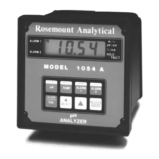
- Page 1 Instruction Manual P/N 5101054AP Model 1054A pH January 1997 Microprocessor pH Analyzer...
- Page 2 ELECTRICAL SHOCK HAZARD READ THIS PAGE BEFORE PROCEEDING! Making cable connections to and serv- Rosemount Analytical designs, manufactures, and tests its products to meet many national and international stan- icing this instrument require access to dards. Because these instruments are sophisticated tech-...
-
Page 3: Table Of Contents
MODEL 1054A pH TABLE OF CONTENTS MODEL 1054A pH MICROPROCESSOR ANALYZER TABLE OF CONTENTS Section Title Page DESCRIPTION AND SPECIFICATIONS ..............Features and Applications..................Physical Specifications-General................Instrument Specifications ..................Recommend Sensors ....................INSTALLATION ......................General ........................Unpacking and Inspection .................. - Page 4 MODEL 1054A pH TABLE OF CONTENTS TABLE OF CONTENTS CONT’D. Section Title Page DIAGNOSTICS AND TROUBLESHOOTING......... Diagnostics................... 8.1.1 Fault Mnemonics .................. 8.1.2 Temperature Compensation ..............Troubleshooting ..................8.2.1 Installation Failure................. 8.2.2 LCD/LED Display Test ................8.2.3 Software Version ................... 8.2.4 Sensor Troubleshooting................
-
Page 5: Description And Specifications
MODEL 1054A pH SECTION 1.0 DESCRIPTION AND SPECIFICATIONS SECTION 1.0 DESCRIPTION AND SPECIFICATIONS • FM AND CSA APPROVED For Class I, Division 2, Gas Groups A, B, C, and D. • pH ELECTRODE DIAGNOSTICS warn user of the need for calibration or electrode replace- ment. -
Page 6: 1.2 Physical Specifications - General
4-wire instrument cable. Model 389 Disposable pH Sensor The Model 1054A pH measures over the full range of 0-14 pH. The Model 1054pH includes programmable temperature corrections current output may be calibrated to represent any 1 to 14 pH span. -
Page 7: Installation
2.3.3 Pipe Mounting (Option-08). The 2" pipe mount- mounting enclosure. ing bracket includes a metal plate with a cutout for the 1054A pH refer to Section 2.3 for mounting the 2.3.1 Panel Mounting (Standard). The Model 1054A analyzer into the plate. Mounting details are shown in pH is designed to fit into a DIN standard 137.9 mm X... -
Page 8: Electrical Wiring
REF UL 508-26.10. 2.4.1 Power Input Wiring. The Model 1054A pH has If the metal support plate is not used, plastic fit- been configured at the factory for either 115 VAC or tings must be used to prevent structural damage 230 VAC power. -
Page 9: Panel Mounting Cutout
MODEL 1054A pH SECTION 2.0 INSTALLATION WHEN INCH AND METRIC DIMS ARE GIVEN MILLIMETER INCH DWG. NO. REV. 41054A01 FIGURE 2-1. Panel Mounting Cutout... -
Page 10: Panel Mounting Tab Installation
MODEL 1054A pH SECTION 2.0 INSTALLATION DWG. NO. REV. 41054A26 FIGURE 2-2. Panel Mounting Tab Installation... -
Page 11: Wall Mounting J-Box Installation
MODEL 1054A pH SECTION 2.0 INSTALLATION ITEM PART NUMBER DESCRIPTION QUANTITY 23058-01 S Assy, J-Box 33030-00 Bracket, wall mtg 9900600 Nut, 6-32 Hex 9910600 Washer, Flat #6 9910610 Washer, Lock Int. #6 9600612 Screw, 6-32 X .75 9510048 Seal, Weathertight DWG. -
Page 12: Wall Mounting J-Box Wiring
MODEL 1054A pH SECTION 2.0 INSTALLATION WHEN INCH AND METRIC DIMS ARE GIVEN MILLIMETER INCH DWG. NO. REV. 41054A08 FIGURE 2-4. Wall Mounting J-Box Wiring... -
Page 13: Pipe Mounting Installation
MODEL 1054A pH SECTION 2.0 INSTALLATION WHEN INCH AND METRIC DIMS ARE GIVEN MILLIMETER INCH DWG. NO. REV. 41054A02 FIGURE 2-5. Pipe Mounting Installation... -
Page 14: Wall Mount Enclosure Dimensions And Mounting
MODEL 1054A pH SECTION 2.0 INSTALLATION WHEN INCH AND METRIC DIMS ARE GIVEN MILLIMETER INCH DWG. NO. REV. 41054A12 FIGURE 2-6. Wall Mount Enclosure Dimensions and Mounting... -
Page 15: Electrical Wiring
MODEL 1054A pH SECTION 2.0 INSTALLATION DWG. NO. REV. 41054A03 FIGURE 2-7. Electrical Wiring... -
Page 16: Integral Preamp Wiring For Group I Panel Mount Enclosure
MODEL 1054A pH SECTION 2.0 INSTALLATION DWG. NO. REV. 41054A04 FIGURE 2-8. Integral Preamp Wiring for Group I Panel Mount Enclosure... - Page 17 MODEL 1054A pH SECTION 2.0 INSTALLATION DWG. NO. REV. 41054A14 FIGURE 2-9. Integral Preamp Wiring for Group II Wall Mount Enclosure...
-
Page 19: Description Of Controls
3.1 KEYBOARD FUNCTIONS. All functions of the C. Alarm 1 and Alarm 2 Setpoint. The ZERO 1054A pH are accessed through keyboard entry alarm setpoint may be adjusted by routines. The analyzer uses no switches or poten- pressing the ALARM 1 or ALARM 2 key ALARM 1 tiometers. -
Page 20: Keyboard Overlay
MODEL 1054A pH SECTION 3.0 DESCRIPTION OF CONTROLS 3.1.1 Item Selection and Value Adjustment Keys. B. Scroll Key ( ). This key is used to The three keys located on the lower right side of the scroll through menu when selected, or... - Page 21 MODEL 1054A pH SECTION 3.0 DESCRIPTION OF CONTROLS TABLE 3-1. Key Description MAIN FUNCTION (PRESS ONCE) SECOND FUNCTION (PRESS TWICE QUICKLY) Displays - pH. Displays - current output (mA or % full OUTPUT scale). Set Function (w/SELECT) - One point standardization of pH.
- Page 22 MODEL 1054A pH SECTION 3.0 DESCRIPTION OF CONTROLS TABLE 3-2. Information Mnemonics MNEMONIC DESCRIPTION MNEMONIC DESCRIPTION Automatic Buffer 1 Access locked - enter security code Automatic Buffer 2 Displays pH output in percent Adjustment to value reading pH Display Incorrect entry...
-
Page 23: Configuration
This will reduce the chance of the Model 1054A pH configuration may be performed accidentally omitting a needed variable. prior to installing it. - Page 24 MODEL 1054A pH SECTION 4.0 CONFIGURATION FIGURE 4-1. Menu Items...
-
Page 25: Alarm Setpoint
MODEL 1054A pH SECTION 4.0 CONFIGURATION TABLE 4-1. Configuration Work Sheet Use this work sheet to assist in the configuration of the analyzer. Date: ____________________ RANGE FACTORY SET USER SET A. Alarm 1 Setup (AL1) 1. Alarm Configuration (On/O..) _________ 2. -
Page 26: Alarm 1 And 2
MODEL 1054A pH SECTION 4.0 CONFIGURATION 4.2 ALARM 1 AND 2. Display Mnemonic “AL1” or 4.2.1 Alarm Setup (AL1/AL2). “AL2”. Used to set alarm relay logic. The alarms may Enter Set Mode by pressing ACCESS key twice. be configured to perform on-off process control. See note below. - Page 27 MODEL 1054A pH SECTION 4.0 CONFIGURATION FIGURE 4-2. Alarms 1 and 2 Configuration...
-
Page 28: Interval Timer
If selected during the control cycle, the display will show “---”. cnt = 1 O.t = 0 NOTE The Model 1054A pH is placed on hold RELAY during the control cycle (from first relay ACTIVATION activation through the wait duration). - Page 29 MODEL 1054A pH SECTION 4.0 CONFIGURATION FIGURE 4-3. Interval Timer Configuration...
-
Page 30: Temperature
Select this item to toggle between °F and °C temper- SCROLL ( ) until "t-C" appears on the display. ature display. The 1054A pH will show all tempera- SELECT to move to the next menu level. “d-t” tures in units selected until the selection is changed. - Page 31 MODEL 1054A pH SECTION 4.0 CONFIGURATION FIGURE 4-4. Temperature Configuration...
-
Page 32: Current Output
ENTER into memory. Selecting this item will allow the 1054A pH to display current output as mA “doc” or as a percent of full SCROLL ( ) then ENTER desired item. - Page 33 MODEL 1054A pH SECTION 4.0 CONFIGURATION FIGURE 4-5. Current Output Configuration...
-
Page 34: Ph Electrode Diagnostics
The following are typical impedance values for new electrode is that the analyzer will read a constant value Rosemount Analytical electrodes (Electrodes stored (usually between 5.0-7.0 pH) in any process or buffer. over a period of time will have higher impedances). - Page 35 MODEL 1054A pH SECTION 4.0 CONFIGURATION FIGURE 4-6. pH Electrode Diagnostics Configuration...
-
Page 36: Solution Temperature Compensation And Isopotential Point
MODEL 1054A pH SECTION 4.0 CONFIGURATION 4.6.1 pH Electrode Diagnostics Setup 4.7 SOLUTION TEMPERATURE COMPENSATION AND ISOPOTENTIAL POINT. Display Mnemonic Enter the Set Menu by pressing the ACCESS key “iSO”. Used for applications where the process' isopo- twice. tential point (“iPH”) and temperature coefficient (“tCO”) SCROLL (Ð) until “InP”... -
Page 37: Solution Temperature Compensation & Isopotential Point Configuration
MODEL 1054A pH SECTION 4.0 CONFIGURATION FIGURE 4-7. Solution Temperature Compensation and Isopotential Point Configuration... -
Page 38: Defaults
MODEL 1054A pH SECTION 4.0 CONFIGURATION 4.8 DEFAULTS. Display Mnemonic “d.t”. This item is 4.8.1 Default Setup (d.t). used to set the configuration of relays and output Enter Set Mode by pressing the ACCESS key default conditions during fault or hold status. See twice. - Page 39 MODEL 1054A pH SECTION 4.0 CONFIGURATION FIGURE 4-8. Default States Configuration...
-
Page 40: Automatic Buffer Mode
MODEL 1054A pH SECTION 4.0 CONFIGURATION 4.9 AUTOMATIC BUFFER MODE. Display Mnemonic NOTE “Ab.”. Software selectable “on” or “off”. Factory If any buffers other than those listed here setting is “on”. With the “off” setting, calibration is will be used (such as some Fisher or Ingold buffers), the “Ab.”... - Page 41 MODEL 1054A pH SECTION 4.0 CONFIGURATION FIGURE 4-9. Automatic Buffer Mode Configuration...
-
Page 42: Alarm Setpoint
MODEL 1054A pH SECTION 4.0 CONFIGURATION 4.10 ALARM SETPOINT. The alarm setpoints should SELECT to adjust the value. The display will acknowledge briefly with “AdJ” followed by the be adjusted after completing the configuration proce- dure as outlined in Sections 4.2 to 4.9. -
Page 43: Output Scale Expansion
MODEL 1054A pH SECTION 4.0 CONFIGURATION 4.11 OUTPUT SCALE EXPANSION. This section B. Full Scale (F.S.) Point (20 mA) should be followed if it is desired to scale the current output to an operating range other than the factory set- Press the pH key to ensure that the analyzer is ting of 0-14 pH full scale. -
Page 44: Simulate Current Output
MODEL 1054A pH SECTION 4.0 CONFIGURATION 4.12 SIMULATE CURRENT OUTPUT. The output can B. Simulate Output in Current “SiC”. The output can be simulated to check the operation of devices such be simulated in mA units if “d-O” in Section 4.5 was as valves, pumps, or recorders. -
Page 45: Start-Up And Calibration
Press the HOLD key twice to place the analyzer in after completion of configuration of the analyzer. The hold. sensor must be wired to the Model 1054A pH for cali- Obtain two buffer solutions with values at least bration. two pH units apart. Unopened buffers have a shelf life of about a year and once opened should 5.2 Temperature Calibration. -
Page 46: Ph Standardization
MODEL 1054A pH SECTION 5.0 START-UP AND CALIBRATION 5.3.2 Calibration With Automatic Features Disabled. Using a calibrated pH instrument with automatic temperature compensation, determine the pH of Press the HOLD key twice to place the analyzer the process or grab sample. The calibration is in hold. -
Page 47: Keyboard Security
MODEL 1054A pH SECTION 6.0 KEYBOARD SECURITY SECTION 6.0 KEYBOARD SECURITY 6.1 KEYBOARD SECURITY. Display Mnemonic “COd”. 6.1.2 Keyboard Security (COd). Select this feature to display the user defined security Enter Set Mode by pressing ACCESS key twice. code. Any three digit number may be used for this code. -
Page 48: Theory Of Operation
7.1 THEORY OF OPERATION. This section is a gen- preamplified at the sensor to allow a stable noise-free eral description of how the Model 1054A pH operates. signal that can be transmitted up to 1,000 feet. This section is for those users who desire a greater understanding of the analyzer's operation. -
Page 49: Diagnostics And Troubleshooting
SECTION 8.0 DIAGNOSTICS AND TROUBLESHOOTING SECTION 8.0 DIAGNOSTICS AND TROUBLESHOOTING 8.1 DIAGNOSTICS. The Model 1054A pH has a diag- 8.1.1 Fault Mnemonics. Table 8-1 lists the fault nostic feature which automatically searches for fault mnemonics and describes the meaning of each. -
Page 50: Troubleshooting
MODEL 1054A pH SECTION 8.0 DIAGNOSTICS AND TROUBLESHOOTING 8.2 TROUBLESHOOTING. The Model 1054A pH 8.2.5 Electrode Input. Display Mnemonic “Ein”. Analyzer is designed with state-of-the-art micro- When selected, the analyzer displays the millivolt processor circuitry, making troubleshooting simple input from the sensor. The displayed value is not tem- and direct. -
Page 51: Troubleshooting Guide
2. Coated glass electrode. 2. Clean glass electrode. 3. Junction plugged. 3. Replace junction. 1054A pH value not the same 1. Grab sample incorrect. 1. Re-evaluate sample technique as grab sample of process. and equipment. 2. Unclear what is correct. -
Page 52: Replacement Parts And Accessories
MODEL 1054A pH SECTION 8.0 DIAGNOSTICS AND TROUBLESHOOTING TABLE 8-5. Replacement Parts and Accessories DESCRIPTION 22966-00 PCB, LCD Digital Display 23025-01 Panel Mounting Kit 23053-00 Mounting Bracket, 2-inch Pipe 23054-01 Mounting Bracket, Wall, with Junction box 23056-02 PCB, 115V Power Supply... -
Page 53: Return Of Materials
MODEL 1054A pH SECTION 9.0 RETURN OF MATERIALS SECTION 9.0 RETURN OF MATERIALS 9.1 GENERAL. To expedite the repair and return of Send the package prepaid to: instruments, proper communication between the cus- Rosemount Analytical Inc. tomer and the factory is important. A return material 2400 Barranca Parkway authorization number is required. - Page 54 The Rosemount customer sales and service organization comprises a network of fully equipped support centers strategical- ly located throughout the world. From many of these locations, the Rosemount Group provides support, distribution of fin- ished products, repair facilities, and training for our customers.
- Page 55 SAMPLE OR MATERIAL THAT HAVE BEEN EXPOSED TO OR USED IN AN ENVIRONMENT OR PROCESS THAT CONTAINS A HAZARDOUS MATERIAL ANY OF THE ABOVE THAT IS SUBMITTED TO ROSEMOUNT ANALYTICAL WITHOUT THE MSDS WILL BE RETURNED TO SENDER C.O.D. FOR THE SAFETY AND HEALTH OF OUR EMPLOYEES. WE THANK YOU IN ADVANCE FOR COMPLIANCE TO THIS SUBJECT.
- Page 57 AND IMPLIED WARRANTIES OF MERCHANTABILITY AND FITNESS FOR A PARTICULAR PURPOSE. RETURN OF MATERIAL Material returned for repair, whether in or out of warranty, should be shipped prepaid to: Rosemount Analytical Inc. Uniloc Division 2400 Barranca Parkway Irvine, CA 92606...
- Page 58 CUSTOMER SUPPORT CENTER 1-800-854-8257 ON-LINE ORDERING NOW AVAILABLE ON OUR WEB SITE http://www.RAuniloc.com Credit Cards for U.S. Purchases Only. Rosemount Analytical Inc. Uniloc Division 2400 Barranca Parkway Irvine, CA 92606 USA Tel: (949) 863-1181 http://www.RAuniloc.com © Rosemount Analytical Inc. 1997...
Need help?
Do you have a question about the 1054A pH and is the answer not in the manual?
Questions and answers