Table of Contents
Advertisement
Quick Links
Download this manual
See also:
User Manual
Q U I C K S T A R T G U I D E
KEPCO
This guide gives a brief introduction to the KLP Power supply, shows simple load connections, and
allows you to verify the power supply is working. The guide also shows you how to use the front panel
controls to perform the most commonly used functions.
Accessing Manuals. First determine your Firmware Version (see below), then download the KLP User
Manual and Developer's Guide from www.kepcopower.com/support/opmanls.htm#klp. Refer to the KLP
User Manual for full specifications, installation considerations and operating instructions. An Installation/
Operation Summary includes hyperlinked references to detailed procedure, but which can be printed as
a handy reference. Refer to the KLP Developer's Guide for a full description of the digital interfaces, their
associated drivers, and the SCPI command language.
Firmware Version. Refer to www.kepcopower.com/utility/util.htm to determine which firmware version is
installed. The KLP can be upgraded to the latest version at no cost using the Kepco Upgrade Utility, also
available at www.kepcopower.com/utility/util.htm.
Accessing Drivers. Drivers are accessed from www.kepcopower.com/drivers/drivers-dl3.htm.
DESCRIPTION. . . . . . . . . . . . . . . . . . . . . . . . . . . . . . . . . . . . . . . . . . . . . . . . . . . . . . . . . . . . . . . . . . . . . 2
UNPACKING. . . . . . . . . . . . . . . . . . . . . . . . . . . . . . . . . . . . . . . . . . . . . . . . . . . . . . . . . . . . . . . . . . . . . . . 2
EQUIPMENT SUPPLIED. . . . . . . . . . . . . . . . . . . . . . . . . . . . . . . . . . . . . . . . . . . . . . . . . . . . . . . . . . . . . 2
ACCESSORIES. . . . . . . . . . . . . . . . . . . . . . . . . . . . . . . . . . . . . . . . . . . . . . . . . . . . . . . . . . . . . . . . . . . . 3
SAFETY. . . . . . . . . . . . . . . . . . . . . . . . . . . . . . . . . . . . . . . . . . . . . . . . . . . . . . . . . . . . . . . . . . . . . . . . . . 3
PRELIMINARY OPERATIONAL CHECK. . . . . . . . . . . . . . . . . . . . . . . . . . . . . . . . . . . . . . . . . . . . . . . . . 4
INSTALLATION. . . . . . . . . . . . . . . . . . . . . . . . . . . . . . . . . . . . . . . . . . . . . . . . . . . . . . . . . . . . . . . . . . . . 5
Input Connections. . . . . . . . . . . . . . . . . . . . . . . . . . . . . . . . . . . . . . . . . . . . . . . . . . . . . . . . . . . . . . . 5
Load Connections. . . . . . . . . . . . . . . . . . . . . . . . . . . . . . . . . . . . . . . . . . . . . . . . . . . . . . . . . . . . . . . 5
Local Sensing (Factory Default). . . . . . . . . . . . . . . . . . . . . . . . . . . . . . . . . . . . . . . . . . . . . . . . . . . . . 6
Remote Sensing Select. . . . . . . . . . . . . . . . . . . . . . . . . . . . . . . . . . . . . . . . . . . . . . . . . . . . . . . . . . . 6
Analog I/O Connections. . . . . . . . . . . . . . . . . . . . . . . . . . . . . . . . . . . . . . . . . . . . . . . . . . . . . . . . . . . 7
GPIB Connections. . . . . . . . . . . . . . . . . . . . . . . . . . . . . . . . . . . . . . . . . . . . . . . . . . . . . . . . . . . . . . . 7
RS 232 Connections (Standard Models). . . . . . . . . . . . . . . . . . . . . . . . . . . . . . . . . . . . . . . . . . . . . . 7
LAN Connections (E-Series Models). . . . . . . . . . . . . . . . . . . . . . . . . . . . . . . . . . . . . . . . . . . . . . . . . 7
OPERATION. . . . . . . . . . . . . . . . . . . . . . . . . . . . . . . . . . . . . . . . . . . . . . . . . . . . . . . . . . . . . . . . . . . . . . . 7
Turning the Power Supply On. . . . . . . . . . . . . . . . . . . . . . . . . . . . . . . . . . . . . . . . . . . . . . . . . . . . . . 7
Enabling/disabling Output Power. . . . . . . . . . . . . . . . . . . . . . . . . . . . . . . . . . . . . . . . . . . . . . . . . . . . 8
Checking or changing Voltage/Current Setpoints. . . . . . . . . . . . . . . . . . . . . . . . . . . . . . . . . . . . . . . 8
Virtual Model Setting. . . . . . . . . . . . . . . . . . . . . . . . . . . . . . . . . . . . . . . . . . . . . . . . . . . . . . . . . . . . . 8
Setting voltage or current. . . . . . . . . . . . . . . . . . . . . . . . . . . . . . . . . . . . . . . . . . . . . . . . . . . . . . . . . . 9
Last Setting Recall. . . . . . . . . . . . . . . . . . . . . . . . . . . . . . . . . . . . . . . . . . . . . . . . . . . . . . . . . . . . . . 10
Viewing/Changing Overvoltage or Overcurrent Protection Values. . . . . . . . . . . . . . . . . . . . . . . . . 10
KLP OUTLINE DIMENSIONS . . . . . . . . . . . . . . . . . . . . . . . . . . . . . . . . . . . . . . . . . . . . . . . . . . . . . . . . 11
KEPCO, INC. " 131-38 SANFORD AVENUE " FLUSHING, NY. 11355 U.S.A. " TEL (718) 461-7000 " FAX (718) 767-1102
©2013, KEPCO, INC
Data subject to change without notice
An ISO 9001 Company.
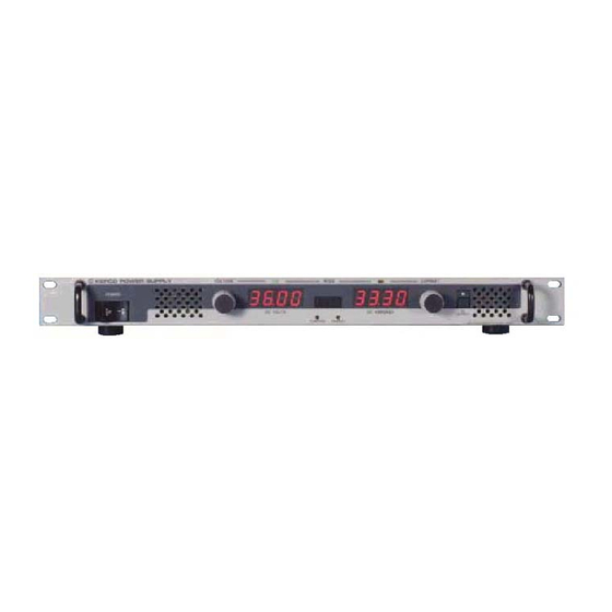
KLP POWER SUPPLY
CONTENTS
228-1616 REV 7
KLP
070113
Advertisement
Table of Contents

Related Manuals for KEPCO KLP 36-60


Summarization of Contents
KLP Power Supply Overview
Accessing KLP Manuals and Guides
Download KLP User Manual and Developer's Guide from www.kepcopower.com/support/opmanls.htm#klp for full specifications and operating instructions.
Firmware Version Check and Upgrade
Determine installed firmware version at www.kepcopower.com/utility/util.htm and upgrade using the Kepco Upgrade Utility.
Accessing KLP Drivers
Download drivers from www.kepcopower.com/drivers/drivers-dl3.htm.
KLP Power Supply Description and Options
KLP Power Supply Description
Universal input, 1200-watt constant power, voltage/current stabilizers with full rectangular output. Seven standard and seven E-Series models.
KLP Power Supply Options
Rapid Output Discharge Circuit (RODC) option available on all KLP models for faster response to voltage reductions.
Initial Setup Procedures
Unpacking and Inspection
Inspect for shipping damage after careful unpacking before operating. File claims immediately if damage is found.
Equipment Supplied
Lists included items such as jumpers, mating connectors, nuts, and the Quick Start Guide.
Accessories and Safety Information
Available Accessories
Details various accessories like line cords, cables, chassis slides, and connectors for enhanced functionality.
Safety Information and Symbols
Explains safety symbols (Caution, Warning) and their meanings related to electrical hazards and potential injury.
Preliminary Operational Check
Connect Power and Initial Power-Up
Connect to source power with breaker OFF, then turn ON. Observe self-test and initial status displays.
Verify Voltage and Current Setpoints
Adjust voltage knob, verify display increments, and set status to >MAX, tapping knob to enter.
Verify Output with External DVM
Connect DVM to M+/M- terminals, enable output, and compare readings with display within tolerance.
Finalizing Operational Check
Enter new voltage values, disable output, and disconnect power. Ensure displays show zero.
Installation and Connections
Installation Guidelines
Install in 19-inch rack, ensure adequate cooling, and keep panels clear. Refer to User Manual for configurations.
Input Power Connections
Provide a properly sized and rated mains lead. Line cords and connectors are available accessories.
Load Connections
Connect load to (+) and (-) DC OUTPUT terminals on the rear panel. Use M+/M- for error sense leads.
Local Sensing Configuration
Local sensing is facilitated by pre-installed jumpers which configure the unit for local sensing.
Sensing Configurations
Local Sensing (Factory Default)
Unit is shipped with local sensing jumpers installed: +S connected to +M and –M connected to –S.
Remote Sensing Setup
Remove local sensing jumpers and connect +S/-S lines at the load. A high frequency bypass network is recommended.
Interface Connections and Power-Up
Analog I/O Connections
Provides access to analog programming inputs, status outputs, and external trigger input via rear panel connector.
GPIB Connections
Connect to computer's GPIB interface card using a standard cable. Default address is 6.
RS 232 Connections (Standard Models)
Connect to a modem using a Null Modem patch cable. Default baud rate is 38400.
LAN Connections (E-Series Models)
Allows communication via built-in web port or other LAN ports using RJ 45 connector.
Turning the Power Supply On
Power Supply Power-Up Sequence
Set POWER ON/OFF circuit breaker to ON. Unit performs a self-test and displays status information.
Output Control and Setpoints
Enabling and Disabling Output Power
Output is disabled on power-up. Tap VOLTAGE/CURRENT control, then press DC OUTPUT switch to enable.
Checking and Changing Setpoints
Tap VOLTAGE/CURRENT control to show setpoints. Rotate control to change, tap again to accept.
Virtual Model Setting
Press FUNCTION switch to show VIRT. Displays show programmed max voltage/current. Exit by rotating controls.
Setting Voltage and Current
Real-time Voltage/Current Adjustment
Rotate controls to change output in real-time when output is enabled. Affects limits in CC/CV modes.
Setpoint Voltage/Current Adjustment
Tap control to enter SET mode, rotate to change setpoint, tap again to accept. Supports coarse/fine adjustment.
Advanced Settings and Protection
Last Setting Recall Function
Saves last setpoint values on shutdown and recalls them on power-up. Enable via Analog I/O Switch 3.
Overvoltage/Overcurrent Protection
Program OVP/OCP values individually. Exceeding limits latches output off. Unit must be cycled to restore.
View and Change Protection Values
Hold PROTECT switch to view setpoints. Operate adjustment control while holding to change values.
Need help?
Do you have a question about the KLP 36-60 and is the answer not in the manual?
Questions and answers