
Related Manuals for Kärcher BD 120 R


Summarization of Contents
Foreword
Foreword
Explains the manual's purpose: to provide comprehensive training and organized documents for servicing.
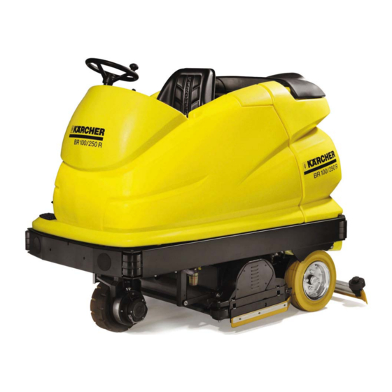
Equipment Features
Technical Features (BR/BD 100/250 R)
Details the technical specifications for the BR/BD 100/250 R model.
Technical Features (BR/BD 100/250 RI)
Details the technical specifications for the BR/BD 100/250 RI model.
Technical Features (BR/BD 120/250 R, BR/BD 120/250 RI)
Outlines technical features for the BR/BD 120/250 R and RI variants.
View from the Left-Hand Side
Illustrates and labels components visible from the left side of the machine.
View from the Right-Hand Side
Shows and labels parts visible from the right side of the equipment.
Rear View
Displays a rear perspective of the machine with labeled components.
Technical Features
Wheel Hub Motor (M1)
Details the wheel hub motor, its components, and operational notes.
Brush Head Assembly
Details the brush head assembly, its parts, and mounting.
Suction System (Suction Beam, Motor)
Explains the suction beam assembly, its components, and the suction motor.
Water and Cleaning Agent System
Covers the water filter, pump, and cleaning agent metering system.
Dirty Water Tank and Recycling
Describes the dirty water tank and the optional recycling mode lever.
Control and Operator Interface
Identifies and explains the functions of controls like the panel and program switch.
Safety and Power Systems
Details safety features like the seat sensor and power systems like battery and charger.
Optional Components (Side Brush, Pre-sweeper Unit)
Describes optional side brush and pre-sweeper unit features.
Unit Functions
Functional Diagram
Illustrates the system's functional flow and component interactions.
Brush System - Contact Pressure Adjustment
Explains how brush contact pressure is adjusted via the lifting motor.
Operator and Service Program Overview
Provides an overview of operator functions and the service program structure.
Operator Functions
Describes operator functions, settings, and the test/display modes.
Initial Operation and Information Menu
Outlines the steps for initial operation and accessing the information menu.
Driving (Without Cleaning Functions)
Explains the driving process without activating cleaning functions.
Wet Scrubbing (with Suction)
Describes the wet scrubbing operation including suction and parameter adjustments.
Suction (Without Scrubbing Mode)
Details the suction-only operation and operator menu.
Polishing (Without Suction)
Explains polishing operation without suction and operator menu.
Operator Functions - Manufacture Settings
Lists manufacture settings for various operator functions.
Modular Electronic Control Circuits
Modular Electronic Control Circuits Overview
Provides an overview of module networking and cross-linking.
Modular System BR/BD 100/250 R
Illustrates the modular system configuration for the BR/BD 100/250 R.
Modular System BR/BD 100/250 R with Side Brush (Optional)
Shows the modular system for BR/BD 100/250 R with an optional side brush.
Modular System BR/BD 100/250 RI
Depicts the modular system configuration for the BR/BD 100/250 RI model.
Emergency Operation (Driving)
Details emergency driving procedures and notes on module failures.
Control Panel Components
Shows the control panel components from below, including modules and switches.
Lifting Module (A4) and Accessories Module (A5)
Illustrates the lifting and accessories modules with their terminal strips and PCBs.
Driving Module (A2) and Cleaning Module (A3)
Shows the physical layout of the driving and cleaning modules.
Lifting Module (A4/1) and Cleaning Module (A3/1) (Optional)
Illustrates optional lifting and cleaning modules with their components.
Service Module (A9)
Details the service module for diagnostics, parameterization, and firmware updates.
Basic Settings and Service Procedures
Test Mode (Head CPU from Version 1.2)
Describes accessing the test mode for CPU version 1.2.
Accelerator Pedal Calibration
Guides through the accelerator pedal calibration process.
Test Mode (Head CPU up to Version 1.1)
Details accessing the test mode for older CPU versions.
Test Mode - Drive Units
Describes the test mode for drive units, detailing switch positions and outcomes.
Setup Menu
Introduces the setup menu and how to access it.
System Menu and Driving Module Parameters
Details system and driving module parameters within the setup menu.
Save Changed Adjustable Parameters
Guides on saving adjusted parameters within the setup menu.
Steering
Describes the steering column, head, and wheel hub motor assembly.
Lifting Motor - Suction Beam (M30)
Details the lifting motor for the suction beam and its microswitch adjustment.
Lifting Motor - Brush Head (M20)
Explains the brush head lifting motor and its limit position adjustments.
Brush Head - Maintenance Work
Covers replacement of brush rollers, disc brushes, and drive belts.
Drive Sensor (B1)
Describes the drive sensor and its automatic calibration.
Magnet Brake (Y1)
Covers removing, checking, and setting the magnet brake and freewheeling lever.
Replacement Intervals
Lists components and their recommended replacement intervals in minutes.
Troubleshooting
Troubleshooting Without Displays
Provides solutions for faults not shown on the display.
Unit Won't Start
Details troubleshooting steps for when the unit fails to start.
Water Volume Too Low
Provides steps to resolve issues with low water volume supply.
Suction Performance Too Low
Addresses issues with low suction performance and adjusting the suction beam.
Dirty Water Tank Overflows
Details troubleshooting for dirty water tank overflows and float switch issues.
Troubleshooting With Displays
Explains the structure of warning messages and their interpretation.
Drive Module (A2) Error Messages
Lists specific error codes for the drive module and their corresponding actions.
Lifting Module (A4) and Cleaning Module (A3) Error Messages
Lists errors for lifting and cleaning modules, including irreparable memory errors.
Head CPU (A1) Error Messages
Lists error codes for the Head CPU module and their actions.
Error Memory
Explains user messages and their meaning in the error memory.
Significant Errors (Head CPU Module A1)
Lists significant errors for the Head CPU module and their potential causes.
Maintenance Work
Maintenance Operations After Working Hours
Outlines maintenance operations to be performed after working hours.
Additional Instructions for Version RI
Provides additional maintenance instructions for version R I, including dust filter replacement.
Circuit Diagrams
Circuit Diagram 0.088-734.0 ORIGINAL, Head CPU (A1)
Presents the circuit diagram for the Head CPU module (A1).
Circuit Diagram 0.088-876.0 REVISED, Head CPU (A1)
Shows the revised circuit diagram for the Head CPU module (A1).
Circuit Diagram for Driving Module (A2)
Provides circuit diagrams for the driving module (A2).
Circuit Diagram for Cleaning Module (A3)
Presents circuit diagrams for the cleaning module (A3).
Circuit Diagram for Cleaning Module - Pre-sweeper Unit (A3/1)
Shows circuit diagrams for the cleaning module (A3/1).
Circuit Diagram for Lifting Module (A4)
Presents circuit diagrams for the lifting module (A4).
Circuit Diagram for Lifting Module - Side Brush (A4/1)
Shows circuit diagrams for the lifting module (A4/1).
Circuit Diagram for Lifting Module - Pre-sweeper Unit (A4/2)
Presents circuit diagrams for the lifting module (A4/2).
Circuit Diagram for Accessory Module (A5)
Shows circuit diagrams for the accessory module (A5).
Circuit Diagram Listing
Provides a listing of components used in the circuit diagrams.
Technical Specifications
Technical Specifications
Lists technical data, unit numbers, circuit diagrams, and operating instructions.
Tools and Torques
Special Tools
Lists special tools required for maintenance and repair.
Tightening Torques
Provides torque specifications for various connections and components.
Need help?
Do you have a question about the BD 120 R and is the answer not in the manual?
Questions and answers