Table of Contents
Advertisement
Advertisement
Table of Contents

Related Manuals for Lexicon PCM 81 - REV 2


Summary of Contents for Lexicon PCM 81 - REV 2
- Page 1 PCM 81 Digital Effects Processor User Guide A Harman International Company...
- Page 2 UNPACKING AND INSPECTION After unpacking the PCM 81, save all packing materials in case you ever need to ship the unit. Thoroughly inspect the PCM 81 and packing materials for signs of damage. Report any shipment damage to the carrier at once; report equipment malfunction to your dealer. PRECAUTIONS Save these instructions for later use.
- Page 3 Fax 781-280-0499 (Service) This document should not be construed as a commitment on the part of Lexicon, Inc. The information it contains is subject to change without notice. Lexicon, Inc. assumes no responsibility for errors that may appear within this document.
-
Page 4: Overview
Introduction Lexicon Introduction Section 2: Basic Operation (continued) Program and Register Banks............2-17 Selecting Effects Vigtig information om sikkerhed ........iv Tempo Mode ................2-19 Tärkeitä turvallisuusohjeita..........iv The Tempo Mode Matrix • Row 0 Tempo • Row 1 Tap Viktig informasjon om sikkerhet ........v Editing an Effect ..............2-21... -
Page 5: Table Of Contents
Introduction PCM 81 Section 4: Presets Section 5: MIDI Operation (continued) Overview...................4-2 Automation ................5-6 Program Bank 0 (P0) ..............4-3 SysEx Automation • Controller Automation • Reset All Multi Effects • Modulation Effects • Special Effects Controllers • MIDI Clock and Clock Commands • PCM 90 Compatibility •... - Page 6 Introduction Lexicon DANSK SUOMI VIGTIG INFORMATION OM SIKKERHED TÄRKEITÄ TURVALLISUUSOHJEITA Gem denne vejledning til senere brug. Säilytä nämä ohjeet tulevaa käyttöä varten. Følg alle anvisninger og advarsler på apparatet. Seuraa kaikkia yksikköön merkittyjä ohjeita ja varoituksia. Apparatet skal altid tilsluttes den korrekte spænding. Der henvises til Käytä...
- Page 7 Introduction PCM 81 NORSK SVENSKA VIKTIG INFORMASJON OM SIKKERHET VIKTIGA SÄKERHETSFÖRESKRIFTER Ta vare på denne veiledningen for senere bruk. Spara dessa föreskrifter för framtida bruk. Følg alle anvisningene og advarslene som er angitt på apparatet. Följ alla anvisningar och varningar som anges på enheten. Apparatet skal alltid anvendes med korrekt spenning.
-
Page 8: Instrucciones Importantes De Seguridad
Introduction Lexicon DEUTSCH ESPAÑOL WICHTIGE SICHERHEITSANWEISUNGEN INSTRUCCIONES IMPORTANTES DE SEGURIDAD Heben Sie sich diese Sicherheitsanweisungen auch für später auf. Befolgen Sie alle auf der Vorrichtung stehenden Anweisungen und Warnungen. Guarde esta instrucciones para uso posterior. Immer nur mit der richtigen Spannung verwenden! Die ebrauchsanweisungen Utilice siempre el voltaje correcto. - Page 9 Introduction PCM 81 FRANÇAIS ITALIANO IMPORTANTI NORME DI SICUREZZA INSTRUCTIONS DE SÛRETÉ IMPORTANTES Conservare le presenti norme per l’utilizzo futuro. Gardez ces instructions pour réference future. Osservare tutte le istruzioni e le avvertenze apposte sull’unità. Observez toutes les instructions et tous les avertissements marqués sur l’appareil. Utilizzare esclusivamente con la tensione di rete corretta.
-
Page 10: Getting Started
Getting Started About the PCM 81................1-2 The Presets • The Algorithms • Tempo Control • Editing • Memory Cards • User Interface Front Panel Overview ..............1-4 Rear Panel Overview ..............1-6 Block Diagram ................1-8 Installation Notes ................1-9 Mounting • Power Requirements • Audio Connections • Control Connections • Connectors •... - Page 11 When you turn the knob, you will adjust the reverb decay. In Prime Blue, ADJUST is patched to several parameters, so that turning the Thank you for your purchase of the PCM 81, one of Lexicon’s most knob changes the effect from a tight chorus, to a chorus with powerful and versatile digital effects processors.
- Page 12 Getting Started PCM 81 well as receive MIDI tempo from an external sequencer or drum unique Patching Modulation system provides machine. In the PCM 81, tempo can control LFO speeds and Time unprecedented control over your effects, with a versatile set of Switch controls, as well as all delay parameters, ensuring that all of internal modulators: LFO, AR Envelope, Envelope Follower, Latch your modulations are in tempo with your music.
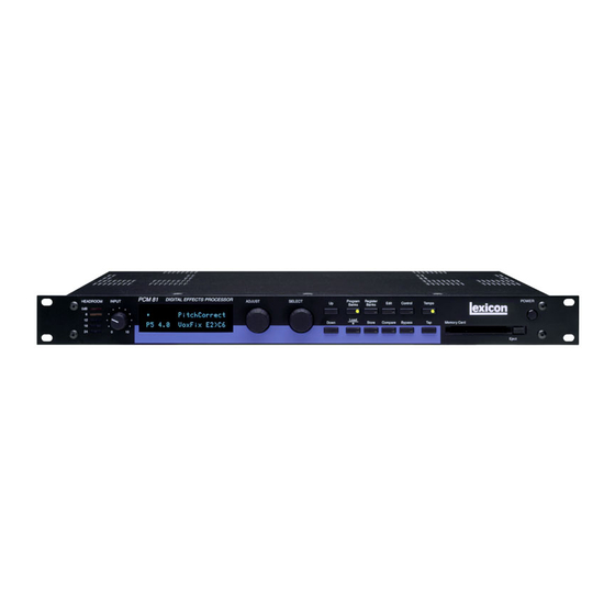
- Page 13 Getting Started Lexicon FRONT PANEL OVERVIEW PCM 81 HEADROOM INPUT DIGITAL EFFECTS PROCESSOR ADJUST SELECT POWER Program Register Banks Banks Edit Control Tempo Chorus+Rvb Load Prime Blue P0 0.0 Memory Card Down ❊ Store Compare Bypass Eject 1. Headroom 5. SELECT Five-position indicator for analog and digital signal levels and Scrolls through presets, registers or parameters.
- Page 14 Getting Started PCM 81 9. Register Banks 16. Tap Enables selection of user memory. If a RAM card is loaded into Sets tempo. Press twice in rhythm to establish tempo rate. the Memory Card slot, each press of this button selects a new Press once to reset LFO.
- Page 15 Getting Started Lexicon REAR PANEL OVERVIEW MIDI AES/EBU INPUT MIDI PUSH PUSH PUSH PUSH PUSH PUSH FOOT FOOT LEVEL BALANCED OUTPUTS -20dB THRU SWITCH CONTROLLER UNBAL S/PDIF BALANCED INPUTS BALANCED INPUTS 1. AC Power 3. AES/EBU and S/PDIF Inputs Standard 3-pin IEC power connector. 100-240V, 50-60Hz AES/EBU format digital connectors conform to AES automatic switching to correct voltage range.
- Page 16 Getting Started PCM 81 6. BALANCED OUTPUTS Sleeve Output impedance is 125Ω, each side, balanced, and levels up – RING to +18dBu maximum full scale. 1/4" phone connectors and SLEEVE Ground XLRs provided. Both S/PDIF and AES outputs are active at all (Shield) Ring times.
-
Page 17: Block Diagram
Getting Started Lexicon BLOCK DIAGRAM S/PDIF Out Digital Audio Transmitter Headroom AES Out Left Input Digital Audio Overload Transmitter Analog Mute In Lvl Input BAL/UNBAL Level 0dB +20dB EFFECTS Mute Right Input Digital In Lvl S/PDIF In -10dBu/+4dBu Control Data... - Page 18 Getting Started PCM 81 INSTALLATION NOTES Mono Applications Use a Y-connector inserted at the analog inputs and outputs to have the signal summed to mono. MOUNTING The PCM 81 uses one EIA-standard rack space, and can be Note: mounted on any level surface or in a standard 19 inch (483 mm) rack.
- Page 19 Getting Started Lexicon MIDI Pin 2 high by convention Five-pin DIN connectors are provided for MIDI IN, THRU and OUT. Use standard 5-pin DIN MIDI cable assemblies, available from your local dealer. CONNECTORS 2 = high 1 = ground Female...
- Page 20 Getting Started PCM 81 Proper setting of Input level on the PCM 81 is dependent on: Overload • Proper signal level into the analog front end to avoid signals The 0db (overload) indicators will light under the following causing overload at the DSP input conditions: •...
- Page 21 Getting Started Lexicon Setting Analog and Digital Input Level Setting Output Level 1. Press Control. While still in Control mode, turn SELECT to 0.6 Output Level. The Output Level parameter has two range positions. The appropriate 2. Press Up or Down until the leftmost digit in the lower lefthand position depends on the level handling capability of the device corner of the display is 0.
- Page 22 Getting Started PCM 81 Connecting to a Mixing Console’s Effects Send (R) Effects Sends Effects Send (L) Channel Input or Effects Return (L) Channel Input or Effects Return (R) MIDI AES/EBU INPUT MIDI PUSH PUSH PUSH PUSH PUSH PUSH FOOT FOOT LEVEL BALANCED OUTPUTS...
-
Page 23: Basic Operation
Basic Operation Modes of Operation..............2-2 Navigating a Matrix • Go or Pro • Info Control Mode ................2-5 Row 0 Audio • Row 1 System • Row 2 Card • Row 3 MIDI • Row 4 Setup • Row 5 Mapx • Row 6 Chain Program and Register Banks............2-17 Selecting Effects Tempo Mode ................2-19... - Page 24 Basic Operation Lexicon The PCM 81 provides a wide range of control over an extraordinary • Press Register Banks to access a bank of 50 memory locations, set of reverb, delay, pitch and modulation effects. All of the controls called registers, where you can store your customized effects.
- Page 25 Basic Operation PCM 81 The Select knob moves you SELECT Simultaneously pressing Up and Down horizontally across the matrix. will always return you to 0.0. An asterisk in the display indicates that Load/✱ is active and, depending on the mode, will load effects or will display The Up and Down additional parameters when pressed.
- Page 26 Basic Operation Lexicon INFO Info messages are displayed when a button is pressed and held down. Generally, info messages describe the function of a button, or provide current status information. Displays the current tempo and the Displays the currently loaded effect clock source (MIDI or internal).
-
Page 27: Control Mode
Basic Operation PCM 81 CONTROL MODE Simultaneously press Up and Down to return to 0.0. Audio *Word Clock Analog In Lvl Dig In Lvl Word Size SCMS Emphasis Bit Output Level System Patch Update Initialize Edit Mode Mix Mode Tempo Mode Bypass Mode Pgm Bypass Mem Protect Auto Load Card... - Page 28 Basic Operation Lexicon ROW 0 AUDIO The following types of errors are detected when the PCM 81 is set to Ext: Audio *Word Clock Analog In Lvl Dig In Lvl Word Size SCMS • No Lock: The PCM 81, at some point, lost lock to the incoming digital audio signal.
- Page 29 Basic Operation PCM 81 Upon loss of lock, or reception of non-audio data, the PCM 81 will • Parity, Indicate that at least one bit (and therefore at mute the digital input and display the following messages when Biphase: least one audio sample) was corrupted. Word Clock or Dig In Status is selected: Parity, Biphase, and Confidence errors are most often caused by Word Clock...
- Page 30 Basic Operation Lexicon 0.1 Analog In Lvl This is a master level control for analog left and right inputs. Use ADJUST to select values from 0-100%. If using only analog inputs, this should be 100% for best audio performance. Values between 0% and 100% are for mixing analog and digital sources.
- Page 31 Basic Operation PCM 81 0.3 WordSize 0.6 Output Level The WordSize control allows you to dither the PCM 81 24-bit word This control allows you to select the maximum output level at the size to match the device receiving digital audio from the PCM 81. PCM 81's analog outputs.
- Page 32 Basic Operation Lexicon 1.1 Mix Mode Whether Tempo Mode is set to Global or Pgm, you can set a new tempo rate by pressing the front panel Tap button twice. Each PCM 81 effect has its own Mix parameter, with the Mix Alternatively, you can choose to have tempo set automatically from setting stored as an integral part of the effect.
- Page 33 Basic Operation PCM 81 To assign an external controller to perform the selected bypass 1.8 Initialize function, press Load/✱ to display Bypass Src. Use ADJUST to select Selecting this control arms the PCM 81 to revert to its factory set- a footswitch or any MIDI controller (or Off).
- Page 34 Basic Operation Lexicon 2.0 Bank Copy 2.1 Load (continued) This control allows you to load audio software from a Memory Card simply by inserting the new card and responding to the display The display will then change to show: prompts. The PCM 81 can load all PCM 80 algorithm cards. It can also share registers, maps, and chains with the PCM 80 via RAM cards.
- Page 35 Basic Operation PCM 81 ROW 3 MIDI Program Change messages 0—49 correspond to PCM 81 Effects 0.0 —4.9 in the current bank. Program Change messages 50—127 Reset Receive Transmit *Pgm Change Automation MIDI are ignored. The current bank can be changed with MIDI Bank *Send Int Clock SysEx...
- Page 36 Basic Operation Lexicon Chain Automation sends all MIDI commands in PCM 80 format, which is also recognized by the PCM 81. As the PCM 80 has only four Banks Any Program Change number can be selected to load any one of (0-3), it cannot load programs from PCM 81 Banks 4 and 5 in ten customized effect “chains".
- Page 37 Basic Operation PCM 81 3.9 Dump Speed Control Mode Matrix Location System Parameter Default Setting Turn ADJUST to select dump speeds of Slow, Medium or Fast to Audio Word Clock Internal 48kHz achieve compatibility with the connected MIDI device. Analog Lvl 100% Digital Lvl Word Size...
- Page 38 Basic Operation Lexicon ROW 5 MAPX A chain can be loaded with a MIDI Program Change message, or by selecting its number directly at Control mode 3.3. Once a chain is loaded, the source assigned to Pgm+ and Pgm– will load the next...
-
Page 39: Program And Register Banks
Basic Operation PCM 81 PROGRAM AND REGISTER BANKS Indicates that the ADJUST knob is patched to one or more parameters in the currently- running effect - in this case, Prime Blue. The PCM 81 has 300 factory-designed programs, organized into six Program Banks of 50 each, and 50 memory locations, called registers, for storing your customized effects. - Page 40 Basic Operation Lexicon The I symbol in the upper left corner of the display indicates that To select an effect stored in a register, press Register Banks. If you have registers stored on a memory card, and have the card the currently running effect has an ADJUST knob patch.
- Page 41 Basic Operation PCM 81 TEMPO MODE You can also choose to have your tempo transmitted as a MIDI Clock signal to control the tempo of connected MIDI devices. The PCM 81 gives you unique control over tempo. In the PCM 81, (Control mode 3.6) If Source is set to MIDI Clock, PCM 81 tempo tempo is not just a matter of setting echo rates.
- Page 42 Basic Operation Lexicon THE TEMPO MODE MATRIX example, the rate is 120 BPM, and you select eighth-note here, the tempo will be 120 eighth-notes per minute. If you select Press Tempo to access the following tempo parameters: quarter-note here, the tempo will be 120 quarter-notes per minute.
- Page 43 Basic Operation PCM 81 1.2 Average When shipped, the PCM 81 will power up with the first preset (P0 0.0 Prime Blue) loaded. The following display will appear: This control allows you to average the last 2-8 taps. Higher numbers mean that the response to incoming taps will be more gradual.
- Page 44 Basic Operation Lexicon Details on how to create your own ADJUST knob patches are given COMPARE at the end of this chapter under Patching. Whenever you edit a PCM 81 effect from the front panel, the LED in the Compare button will light. This lets you know that the effect...
- Page 45 Basic Operation PCM 81 Each preset has a Soft Row of parameters which have been specifically selected to provide everything you need to play with the effect. This example shows the Soft Row for P0 0.0 Prime Blue. An asterisk in front of a displayed parameter indicates additional parameters are available when you press Load/✱.
- Page 46 Basic Operation Lexicon BYPASS The front panel Bypass button is always active, and will turn on the type of bypass (AllMute, InputMute, OutputMute, or Bypass) selected in Control Mode 1.3. Turn ADJUST to select Off. When you press Bypass, the button LED will light and a message will be displayed to inform you that bypass is on.
- Page 47 Basic Operation PCM 81 When you store an effect, the following things are saved: Renaming the Effect • Values of all Edit matrix parameters. This includes the initial Renaming an effect is straightforward. With the asterisk and the values for any patch destinations when Patch Update (Control cursor positioned as shown, turn ADJUST to select a new character.
- Page 48 Basic Operation Lexicon Selecting a Bank and Register Location THE FULL EDIT MATRIX Press Load/✱ to move the asterisk to the Register Bank ID. Setting Edit Mode to Pro (Control Mode 1.0) gives you access to the full parameter matrix of the algorithm for any loaded effect whenever you press the front panel Edit button.
-
Page 49: Concert Hall
Basic Operation PCM 81 Concert Hall Controls FX Adjust *InLvl/Pan High Cut Voice Dif FX Mix FX Width *ADJUST Rvb Time Low Rt Mid Rt Crossover Rt HC Pre Delay *Ref Lvl/Dly *Pst/Gld Plate Rvb Design Size Diffusion Depth Spin Chorus Link Rvb Width... - Page 50 Basic Operation Lexicon Creating a Soft Row When you release the Edit button, the display will change to the Soft Row Assignment display shown below. The Edit button In Pro mode you still have complete access to the Soft Row, which LED will begin flashing and will continue to flash as long as you appears above row 0 of the full edit matrix.
- Page 51 Basic Operation PCM 81 The Soft Row assigned to an effect appears above Row 0 in the full Edit Matrix. Controls Controls Controls Rvb Time Rvb Time Rvb Time Rvb Design Chorus Mod: LFO Mod: Sw 1 (Soft Row) S.0 Mix S.1 High Cut S.2 FX Width S.3 Mid Rt...
- Page 52 Basic Operation Lexicon PATCHING To make a patch, use SELECT and the Down button to move down through the Edit matrix to the Patch row. A display such as the Patching is the ability to assign a control (Source) to any PCM 81 following will appear.
- Page 53 Basic Operation PCM 81 Patch Sources Internal MIDI Controller Numbers Sw 2 (PCM 81 interprets 000 as (PCM 81 interprets 032 as General 8 Bank Select) Bank Select) Sine Sw 1 & 2 Porta Ctl Mod Wheel Ctl 33 Cosine Mono Lvl Ctl 85 Breath...
- Page 54 Basic Operation Lexicon Assigning a Destination When Delayed is selected, the stored value of the parameter will continue to be in effect until the controller is moved. (It is, Once you have selected a Source, press Load /✱ and the display therefore, a good idea to set a sensible value to the parameter in will change to allow you to assign a Destination (Dst).
- Page 55 Basic Operation PCM 81 This display allows you to assign Destination values to specific • With any modulation parameter selected as a Source, press Edit Source values. These assignments are made in pairs, each with a to jump to the Modulation row position of the Source. For value for the Source and a value for the Destination.
- Page 56 Basic Operation Lexicon Turn SELECT to select Patch 1 (which is set to Off). ✱ ✱ The FX Width parameter is now assigned as the patch Destination. Turning ADJUST will scroll through the entire list of available patch Now, press Load/✱ to bring up the Values display. This will show Sources.
- Page 57 Basic Operation PCM 81 Adjusting the Modulation Source Parameters ✱ Continuing the previous example, we’ll adjust the rate of the LFO by jumping to it from the Patch row. Press Load/✱ repeatedly to return to the Patch 1 Source selection Now, press Edit to jump back to your previous position in the Patch display.
- Page 58 Basic Operation Lexicon Press Load/✱ once to move the ✱ to the right of the Source value. Note that the ✱ remains in the same position, so you can just turn When the ✱ is in this position, ADJUST will change the Destination ADJUST to set the new Destination value.
- Page 59 Basic Operation PCM 81 Press Edit to jump directly to the FX Width parameter in the Controls Row. ✱ ✱ Patch Destination Indicator If the ✱ is not at the left of the Source value, press Load/✱ three times to move it there. (You can take a short cut instead — simultaneously press Down and Load/✱...
- Page 60 Basic Operation Lexicon By adding this pivot point, we have put a “kink” in the patch. The Mod Row Patches value of the Destination parameter no longer moves in a straight AR ENV, Latch, Sw 1 and Sw 2 are each activated by assigning a line between 0 and 90.
-
Page 61: Algorithms And Parameters
Algorithms and Parameters About the Algorithms..............3-2 The 4-Voice Algorithms ..............3-2 Concert Hall • Plate • Chamber • Inverse • Infinite The 6-Voice Algorithms ..............3-9 Glide>Hall • Chorus+Rvb • M-Band+Rvb The Resonant Chord Algorithms ..........3-13 Res1>Plate and Res2>Plate The Parameters ................3-15 Chorus •... -
Page 62: About The Algorithms
The algorithm name appears on the upper line of the display Pitch algorithms: Quad>Hall, Dual-Chmb, Dual-Plt, Dual-Inv, whenever an effect is selected. Stereo-Chmb, VSO-Chmb and Pitch Correct each offer a unique type of pitch shifting, combined with an uncompromised Lexicon Chorus +Rvb reverb. P0 0.0... - Page 63 Algorithms and Parameters PCM 81 V1 Fbk V1 Lvl V1 Pan Voice Delay V2 Pan V2 Fbk V2 Lvl InLvl L In InPan PstDly REVERB Rvb In PstDly Mix Width Width PstDly InPan R In InLvl V3 Fbk V3 Lvl V3 Pan Voice Delay...
- Page 64 Algorithms and Parameters Lexicon CONCERT HALL V1 Fbk V1 Lvl V1 Pan This algorithm emulates a real Voice concert hall. The reverberation is Delay very clean, and designed to remain V2 Pan V2 Fbk V2 Lvl behind the direct sound — adding...
- Page 65 Algorithms and Parameters PCM 81 PLATE V1 Fbk V1 Lvl V1 Pan The Plate algorithm mimics the sound of Voice Delay metal plates, with high initial diffusion and a relatively bright sound. This makes them a V2 Pan V2 Fbk V2 Lvl good choice for enhancing any type of InLvl...
- Page 66 Algorithms and Parameters Lexicon CHAMBER V1 Fbk V1 Lvl V1 Pan The Chamber algorithm produces an even, Voice relatively dimensionless reverberation, with Delay little change in color as the sound decays. V2 Pan V2 Fbk V2 Lvl The initial diffusion is similar to the Concert...
- Page 67 Algorithms and Parameters PCM 81 INVERSE V1 Fbk V1 Lvl V1 Pan The Inverse algorithm allows you to Voice vary the slope of the initial portion Delay of the reverb envelope. The slope V2 Pan can decay, remain level, or rise over V2 Fbk V2 Lvl InLvl...
- Page 68 Algorithms and Parameters Lexicon INFINITE V1 Fbk V1 Lvl V1 Pan Infinite is acoustically similar to the Chamber Voice Delay algorithm, with the addition of an Infinite parameter. When this parameter is turned V2 Pan V2 Fbk V2 Lvl InLvl on, the input to the reverberator ramps off.
- Page 69 Algorithms and Parameters PCM 81 INFINITE (continued) Controls FX Adjust *InLvl/Pan High Cut Voice Dif FX Mix FX Width *ADJUST Rvb Time Low Rt Mid Rt Crossover Rt HC Pre Delay Infinite *Ref Lvl/Dly *EkoFbk/Dly *Pst/Gld Rvb Design Size Diffusion Shape Spread Spin...
- Page 70 Algorithms and Parameters Lexicon GLIDE>HALL V3 X-Fbk V2 X-Fbk A stereo pair of 2-tap gliding delays feeds six V1 X-Fbk individually adjustable delay voices. Each V1 Lvl Voice V1 Pan V3 Fbk voice has its own level, feedback, delay, InLvl V2 Lvl A&B Dly L...
- Page 71 Algorithms and Parameters PCM 81 CHORUS+RVB V3 Fbk The Chorus effect has six separately V2 Fbk adjustable voices — allowing the V1 Fbk V1 Depth, V1 Rate V1 Lvl PCM 81 to sound like a rack of six V1 Chorus V1 Pan digital delay boxes.
- Page 72 Algorithms and Parameters Lexicon M-BAND+RVB V3 Fbk This effect features six separately V2 Fbk adjustable voices, each with its own V1 Fbk level control, delay time, low and V1 Lvl V1 Pan V1 HiCut V1 LoCut high frequency filters, feedback and...
- Page 73 Algorithms and Parameters PCM 81 THE RESONANT CHORD ALGORITHMS V1 Res V1 HiCut V1 Delay V1 Lvl V1 Fbk V1 Pan V2 Res V2 HiCut V2 Delay RES1>PLATE AND RES2>PLATE V2 Lvl V2 Fbk V2 Pan V3 Res The Resonant Chord effects use impulsive energy V3 HiCut V3 Delay V3 Lvl...
- Page 74 Algorithms and Parameters Lexicon Res1>Plate Controls FX Adjust *InLvl/Pan FX Mix FX Width *ADJUST Rvb Time Low Rt Mid Rt Crossover Rt HC Pre Delay *Ref Lvl/Dly EkoFbk/Dly Rvb Design Size Diffusion Attack Spin Link *Rvb In/Out Levels *Master *Voice 1...
- Page 75 Algorithms and Parameters PCM 81 THE PARAMETERS MstDepth and MstRate Two Master Chorus parameters in the first row position allow PCM 81 parameters are organized into labeled rows within each Chorus, Depth and Rate for all voices to be simultaneously scaled. edit matrix.
- Page 76 Algorithms and Parameters Lexicon CONTROLS Voice Dif (continued) This parameter is available in all of the 4-Voice Algorithms, and in Glide>Hall. It controls the density of echoes in the delay voices, FX Adjust independently of Reverb diffusion. High levels of diffusion thicken, FX Adjust controls the level of the processed (wet) signal before it or smear, the echoes.
- Page 77 Algorithms and Parameters PCM 81 Value Display Label Description DELAY TIME MONO Phase Normal Mono In each algorithm, the Delay Time row contains parameters for delay settings of each voice, as well as master delay parameters for R, L Phase Normal R/L stereo all voices.
- Page 78 Algorithms and Parameters Lexicon DELAY TIME Algorithm Delay Time (continued) Concert Hall 0-1.365 sec Plate 0-1.365 sec GldRange Chamber 0-1.365 sec In all of the 4-Voice algorithms, and in the Chorus+Rvb algorithm, this parameter controls the range over which changes to the voice Inverse 0-1.365 sec...
- Page 79 Algorithms and Parameters PCM 81 FEEDBACK/CROSS FEEDBACK Mstr Fbk, Mstr X-Fbk These parameters allow the feedback and cross feedback levels for Parameters in this row provide level and phase setting for feedback all voices to be simultaneously scaled over a range of 0-100%. of individual voices, as well as a master feedback parameter for all voices.
- Page 80 Algorithms and Parameters Lexicon FILTERS A Left (A Lvl L and A Dly L) These parameters control the output level and delay time of the left In the M-Band+Rvb algorithm, Row 5 contains parameters for channel A Glide Delay. A Lvl L has a range of Full (+0dB), Phase...
- Page 81 Algorithms and Parameters PCM 81 left channel glide delay feedback input. The range of these In the Res1>Plate and Res2>Plate algorithms, positions 1-6 contain parameters is from +100% down to 1% (Phase Normal feedback), both level and feedback parameters for each of the six resonator 0% (off), -1% up to –100% (Phase Inverted feedback).
- Page 82 Algorithms and Parameters Lexicon MODULATION (continued) Patch Sources Shape • P Width Determines the proportion of each pulse wave High Note cycle for which the LFO is on (1-99%). For example, setting P Width to 50% means that Depth Clk Cmnds the LFO is on for half of its cycle.
- Page 83 Algorithms and Parameters PCM 81 • Repeat As long as the threshold source remains at or Mod: Latch above T Lvl, the envelope cycles from attack to The latch is a very flexible modulation source. It can be used to do release.
- Page 84 Algorithms and Parameters Lexicon MODULATION • Mode Determines the “shape” of the switch output. (continued) Three settings are available: Switch, Ramp, and Off. When Switch is selected, the Mod: Latch (continued) transition from on to off is instantaneous, i.e. the switch output resembles a pulse wave.
- Page 85 Algorithms and Parameters PCM 81 PANNING Sw Value Parameters in the Panning row provide control of panning of T Lvl individual effects voices, as well as a master panning parameter for T Src all voices. The switch cycles between 127 and 0 as long as T Src is at or above T Lvl.
- Page 86 Algorithms and Parameters Lexicon PATCHING This gives you a linear relationship between the parameter and the (continued) controller. Inverse control is accomplished easily by reversing these settings. As many as eight pairs of Destination/ Source values can Values be assigned here, providing an exciting new level of dynamic control.
- Page 87 Algorithms and Parameters PCM 81 PITCH Active This parameter allows you to define the number of active voice The Resonant Chord algorithms: Res1>Plate and Res 2>Plate each resonators. You can choose from 0 (no resonators active) to 6. have a Pitch row that contains the parameters for setting and Setting the value to 1 will limit pitch assignments to Voice 1’s controlling the tuning of the effect's resonators.
- Page 88 Algorithms and Parameters Lexicon PITCH (continued) This parameter establishes a key signature for the pitch selection of the voice intervals. The range of this value is the 12 keys from C, Res 2>Plate Pitch Parameters (continued) C#, etc., up to B.
- Page 89 Algorithms and Parameters PCM 81 Both of these generate out-of-key harmonization: • The Scale is Major. • The Root is 1. (C Major Ionian) • Shift Down Take the input pitch assign, round it up a • Voice 1 Pitch is assigned to Unison. half-step to an in-key pitch, calculate the •...
- Page 90 Algorithms and Parameters Lexicon RESONANCE Duration In the Inverse algorithm, Duration determines the length of time, In the Resonant Chord algorithms: Res1>Plate and Res2>Plate, this in milliseconds, which passes before the cutoff in Inverse effects. row contains high cut filter and resonance controls for each voice, as well as master high cut and resonance controls for all voices.
- Page 91 Algorithms and Parameters PCM 81 the Size control is varied. For some special effects, Mid Rt, Spread and Size can be unlinked. Available in the Concert Hall and Glide>Hall algorithms, Definition affects the echo density buildup rate during the latter part of the decay period.
- Page 92 Algorithms and Parameters Lexicon RVB TIME Pre Delay (continued) Pre Delay adjusts an additional time delay between the input of signal and the onset of reverberation. The maximum range is Low Slope and Mid Slope 930ms. This control is not intended to mimic the time delays in These parameters are only available in the Inverse algorithm.
- Page 93 The PCM 81 contains 7 Pitch algorithms, each combined with 0, causes the glide delays to take a minute or more, allowing uncompromised Lexicon reverb to provide a wide range of useful subtle changes in delay times and echoes with no noticeable pitch pitch shift effects, ranging from pitch correction to special effects.
- Page 94 Algorithms and Parameters Lexicon ABOUT THE PITCH ALGORITHMS Much of the art of pitch shifting, therefore, is in determining the (continued) appropriate intervals for sampling and the optimal points for Configuration and routing control is provided by a dedicated splicing. As the PCM 81 Pitch algorithms gives you significant Submixer incorporated into each of these five algorithms.
- Page 95 Algorithms and Parameters PCM 81 QUAD>HALL V1 X-Fbk V2 X-Fbk The Quad>Hall algorithm, is a 4-voice pitch shifter in series with the Concert Hall reverb. As in the multi- V1 Lvl V1 Fbk V1 Pitch V1 Pan voice algorithms, each voice has its own delay, level, V2 Fbk V2 Lvl V2 Pitch...
- Page 96 Algorithms and Parameters Lexicon The following five Pitch FX algorithms: Dual-Chmb, Dual-Plt, Dual Shifter V1 X-Fbk Dual-Inv, Stereo-Chmb and VSO-Chmb are created from 3 Reverb blocks and 3 Pitch Shift Effect blocks. The individual V1 Fbk V1 Lvl reverb and effect blocks are described, followed by the...
- Page 97 Algorithms and Parameters PCM 81 DUAL-PLT Dual Shifter V1 X-Fbk This algorithm includes a dual pitch shifter combined with the V1 Fbk Plate reverb. The pitch shifter has two voices. Each voice has V1 Lvl independent controls for pitch, level, delay, pan, feedback and V1 Pitch V1 Pan cross-feedback.
- Page 98 Algorithms and Parameters Lexicon DUAL-INV Dual Shifter V1 X-Fbk This algorithm includes a dual pitch shifter combined with the V1 Fbk Inverse reverb. The pitch shifter has two voices. Each voice has V1 Lvl independent controls for pitch, level, delay, pan, feedback and...
- Page 99 Algorithms and Parameters PCM 81 STEREO-CHMB Stereo Shifter The Stereo-Chmb algorithm is optimized for the best possible shifted audio quality while maintaining the stereo imagery of Stereo the source material. Pitch is adjustable up or down over a 3 Pitch Shifter octave range with a resolution of 1 cent.
- Page 100 Algorithms and Parameters Lexicon VSO-CHMB For example, to compress a 30 second spot to 24 seconds, the playback speed must be increased by 20%. The spot now has the The VSO-Chmb algorithm provides the same high quality shifter as correct run length, but increasing the speed created an upward Stereo-Chmb, designed for on the fly pitch correction of varispeed pitch shift of 386 cents.
- Page 101 Algorithms and Parameters PCM 81 Like the Stereo-Chmb algorithm, VSO-Chmb is combined with a The Chamber reverb produces an even, relatively dimensionless stereo chamber reverb. This adds considerable flexibility. You can reverberation, with little change in color as the sound decays. The for example, add reverb to the material as it is being pitch initial diffusion is similar to the Concert Hall algorithm, but the corrected (great for voiceovers, etc.).
- Page 102 Algorithms and Parameters Lexicon Dual-Chamb Controls LvlAdjust *InLvl/Pan FX Width *ADJUST Submixer Sends Returns Routing *Mix *InLvl *In W *HiCut *LoCut *OutLvl *Out W Rvb Time Low Rt Mid Rt Crossover Rt HC Pre Delay *Ref Lvl/Dly *Eko Fbk/Dly Rvb Design...
- Page 103 Algorithms and Parameters PCM 81 Dual-Inv Controls LvlAdjust *InLvl/Pan FX Width *ADJUST Submixer Sends Returns Routing *Mix *InLvl *In W *HiCut *LoCut *OutLvl *Out W Rvb Time Low Slope Mid Slope Crossover Rt HC Pre Delay *Ref Lvl/Dly Rvb Design Duration Diffusion Shape...
- Page 104 Algorithms and Parameters Lexicon THE PITCH PARAMETERS Lowest note of some typical sources: • Piano • Tenor Sax • Bass guitar • Vocal: bass MstrCents • Guitar • Vocal: baritone This is a master pitch offset control for all voices. The value dialed in here will be added to all voices.
- Page 105 Algorithms and Parameters PCM 81 Voice 1-4 (or 1-2) When shifting chords or full bandwidth material, first set the amount of shift. If you need to minimize the delay caused by the These parameters determine the amount of pitch shift for the left shifter, set Low Pitch to the lowest value and slowly increase it to and right input channels.
- Page 106 Algorithms and Parameters Lexicon Sends Routing Returns Rvb into FX FX into Rvb OUTPUTS Stereo Stereo Effect Reverb and Delay High Cut Low Cut High Cut Low Cut InLvl Stereo Stereo Effect Reverb and Delay Rvb Input Level FX Input Level...
- Page 107 Algorithms and Parameters PCM 81 Sends Value Rvb Sends FX Sends Returns Value Rvb Returns FX Returns Stereo (0) L to left Rvb In L to left FX In Mono (150) left + right Rvb Out to L left + right FX Out to L R to right Rvb In R to right FX In...
-
Page 108: Useful Configurations
Algorithms and Parameters Lexicon USEFUL CONFIGURATIONS Stereo Series 1 Submixer Routing It is possible to arrange the stereo Rvb and FX inputs and out- Rvb into FX puts into a variety of useful configurations by simply adjusting Submixer Sends Submixer Returns the Sends, Returns and Routing parameters. - Page 109 Algorithms and Parameters PCM 81 Mono In/Stereo Out Series 1 Mono In/Stereo Out Series 1 Submixer Routing • A mono mix of the left and right inputs is sent into the Rvb Rvb into FX block. Submixer Sends Submixer Returns Mono Rvb Mix FX Mix...
- Page 110 Algorithms and Parameters Lexicon Stereo Parallel Submixer Routing Stereo Parallel Parallel • The Rvb and FX blocks process the left and right Submixer Sends Submixer Returns inputs independently. Stereo Rvb Mix Stereo • The stereo outputs of both the Rvb and FX blocks are combined at the main outputs.
- Page 111 Algorithms and Parameters PCM 81 Dual Mono In/Stereo Out Dual Mono In/Stereo Out Submixer Routing Parallel • The Rvb block processes only the left input as a Submixer Sends Submixer Returns mono signal, and the FX block processes only the Mono Rvb Mix Stereo...
-
Page 112: Rvb And Fx Block Controls
Algorithms and Parameters Lexicon RVB AND FX BLOCK CONTROLS The Rvb and FX blocks shown in the previous configurations represent the Stereo Reverb and 2-Voice Pitch Shift effects. Each of these blocks has its own set of controls, shown in the diagrams below. - Page 113 Algorithms and Parameters PCM 81 These effect block Submixer Sends Returns Routing *Mix *InLvl *In W *HiCut *LoCut *OutLvl *Out W controls are also found in the Submixer row of each parameter matrix (pictured here). These parameters provide independent control of input and output level and width, as well as high cut and low cut parameters for each FX and Rvb block.
-
Page 114: The Pitch Correct Algorithm
Algorithms and Parameters Lexicon THE PITCH CORRECT ALGORITHM pitch. The Pitch Detect display shows the pitch of the input source in real time, displayed as a chromatic note and ±cents so that you The Vocal Fix Pitch Correct algorithm is designed to work with can see exactly where and how much correction is needed. - Page 115 Algorithms and Parameters PCM 81 The Chamber reverb produces an even, relatively Chamber EkoFbk L dimensionless reverberation, with little change in color as the sound decays. The initial diffusion is similar to the Concert Hall EkoDly L algorithm, but the sense of space and size is much less RefLvl L obvious.
- Page 116 Algorithms and Parameters Lexicon Correction Low Pitch and High Pitch This parameter lets you control the amount of off-pitch correction These controls allow you to set a range of pitches to be detected. (0-100%) applied. When set to 0, no correction is applied. When...
- Page 117 Algorithms and Parameters PCM 81 Splice This parameter allows you to change the amount of time used to crossfade the splices that occur whenever pitch is shifted. A value of 8ms is appropriate for most material. Higher values will produce longer/smoother cross-fades, but the intelligibility of transients and high frequency content may be affected.
-
Page 118: Alphabetical Index Of Presets
Presets Overview ..................4-2 Program Bank 0 (P0)..............4-3 Multi Effects • Modulation Effects • Special Effects Program Bank 1 (P1)..............4-8 Rhythmic Echo and Delay Effects • Ambience Effects Program Bank 2 (P2)..............4-13 EQ Effects • Spatial Effects • Gain Effects • Resonant Chord Effects Program Bank 3 (P3)..............4-19 Reverb Effects •... - Page 119 Presets Lexicon The PCM 81 has 300 factory-designed presets which are organized Matrix into six banks of 50 each (labeled P0- P5). Each bank is organized Bank Location Preset Type in a matrix of 5 rows of 10. Press the front panel Program Banks 0.0–1.9...
-
Page 120: Program Bank 0 (P0)
Presets PCM 81 PROGRAM BANK 0 (P0) 0.4 Wet Chorus 3 ADJUST: FX Mix 0–100 A variation of Wet Chorus 2 with even thicker chorus (bordering on a slight flange) and slightly modified delays. ADJUST controls the MULTI EFFECTS combination of delays and chorus with reverb. 0.0 Prime Blue ADJUST: Efx/Rvb X 0–127... - Page 121 Presets Lexicon PROGRAM BANK 0 (P0) 1.4 X Eko Flange ADJUST: X-Fbk 0–100 (continued) A stereo flanger with rhythmic echoes feeding into stereo reverb. ADJUST controls the cross-feedback of the echoes (which causes MULTI EFFECTS (continued) them to bounce from side to side as they repeat). Press Tap to synchronize the echoes with rhythmic sources.
- Page 122 Presets PCM 81 MODULATION EFFECTS 2.5 Env:PanKorus ADJUST: Chorus 0–127 The AR Envelope drives the speed of the pan based on the presence or absence of input signal. ADJUST varies the chorus amount. 2.0 FSw2 Elevate ADJUST: Feedback 0–99 Similar to Detuned Ekos, multiple echo voices with diffusion, mod- 2.6 6 Vox Flange ADJUST: MstrDepth 0–100...
- Page 123 Presets Lexicon PROGRAM BANK 0 (P0) SPECIAL EFFECTS (continued) MODULATION EFFECTS 3.6 Under Water ADJUST: DrownKnob 0–100 (continued) This effect really pulls you under! It will submerge any track under water. ADJUST controls the over all rate of the effect.
- Page 124 Presets PCM 81 4.2 RoxStutter ADJUST: FX Mix 0–100 4.7 V-Eliminate ADJUST: Cut Zone 0–127 Use on those strong rock and roll lead vocals. The trailing echoes This effect is a vocal eliminater. It is similar to Remove Cntr, in that on voices 3 and 4 go longer as the signal disappears.
-
Page 125: Program Bank 1 (P1)
Presets Lexicon PROGRAM BANK 1 (P1) 0.3 OffBeat Eko2 ADJUST: DarkKnob 0–127 Additional rhythmic delay voices are used to create a more complicated syncopation pattern than OffBeat Eko. ADJUST RHYTHMIC ECHO AND DELAY EFFECTS controls high cut filters in the echo feedback paths – great for “tape”... - Page 126 Presets PCM 81 0.8 Six Trips ADJUST: EchoSlope 0–127 1.2 TapEkoGate 2 ADJUST: GateWidth 0–127 Rhythmic delay voices produce a six note triplet pattern. Each This is a variation of TapEkoGate 1 with different echo rhythms. repeat gets progressively louder. ADJUST controls the slope of the ADJUST determines the portion of the four beats in which the gate first six repeats.
- Page 127 Presets Lexicon PROGRAM BANK 1 (P1) 2.1 Tape Echo ADJUST: DarkKnob 0–127 (continued) This preset simulates a stereo tape echo. The echo rate is tempo controlled. Press Tap to synchronize with rhythmic material. RHYTHMIC ECHO AND DELAY EFFECTS (continued) ADJUST controls high frequency damping – the echoes get darker as they repeat.
- Page 128 Presets PCM 81 2.6 BandEko Rvb ADJUST: Center Fc 0–127 3.2 Dly>EQ>Pans ADJUST: Mstr Fbk 0–100 In this preset, the outputs of a stereo band pass filter are sent to left The input signal is split into two frequency bands by this effect. The and right rhythmic delays.
- Page 129 Presets Lexicon PROGRAM BANK 1 (P1) 4.2 Zoom Over ADJUST: Speed 1–25 (continued) Run an effect (or even a continuous synthesizer drone) into this preset, and the sound will approach you from the center, spread AMBIENCE EFFECTS out to the sides as it passes overhead, and recede into the distance behind you.
-
Page 130: Program Bank 2 (P2)
Presets PCM 81 4.6 2WayStreet ADJUST: Speed 1–100 PROGRAM BANK 2 (P2) Another variation of AmbientCarBy. This preset produces both left-to-right and right-to-left drive-by effects — like listening to the EQ EFFECTS sound of traffic on a two-way street. The speed for each direction is slightly different. - Page 131 Presets Lexicon PROGRAM BANK 2 (P2) 0.8 BandReject 4 ADJUST: FX Mix 0–100 (continued) Three independent modulators are used to sweep filters and pan the outputs of this preset. The result is an effect with constantly EQ EFFECTS (continued) changing tonal and spatial characteristics. A touch of reverb adds some overall ambience.
- Page 132 Presets PCM 81 1.3 Go Away ADJUST: How Far? 0–127 1.7 Backstage ADJUST: How Far? 0–127 Use this preset to take a stereo source and move it anywhere from Remember what the concert sounded like from the green room? If in your face to far, far away.
- Page 133 Presets Lexicon PROGRAM BANK 2 (P2) 2.6 X-TremoloTap ADJUST: Depth 0-127 (continued) This a variation of TremoloTap1. In this preset the left and right modulation are 90° out of phase, producing a stereo effect that SPATIAL EFFECTS (continued) doesn’t collapse in a mono mix. If the input source is mono, the sound will seem to move from side to side.
- Page 134 Presets PCM 81 3.0 MultiFxFade ADJUST: FX Mix 0–100 3.6 AutoFadeIn 3 ADJUST: Rvb Lvl 0–127 The AR envelope is used to create a moderate fade-in of chorus, This variation of AutoFadeIn 1 has shorter delay times and a lighter delay and reverb effects.
- Page 135 Presets Lexicon PROGRAM BANK 2 (P2) 4.4 ModalImpulse ADJUST: Tone 0–50 (continued) The resonators in this preset are tuned to arpeggiate a modal 7th chord. ADJUST changes the overall tone of the arpeggiated notes. RESONANT CHORDS EFFECTS STET The rhythm of the arpeggio is tempo controlled. Press Tap twice to synchronize it to the beat.
-
Page 136: Program Bank 3 (P3)
Presets PCM 81 4.7 LvlSweeper ADJUST: Color 0–24 0.1 Small Room ADJUST: Liveness 0–60 This preset is driven by level. Any input that exceeds the input Use ADJUST to quickly change the ambient characteristics of this threshold will cause a little burst of resonators that quickly swirl typically tight sounding room. - Page 137 Presets Lexicon PROGRAM BANK 3 (P3) 1.4 Slap Plate ADJUST: Decay 0–60 (continued) Added reflections to a medium sized plate. Vary the Delay Master in the soft row to increase the delay time. ADJUST sets reverb REVERB EFFECTS (continued) decay.
- Page 138 Presets PCM 81 2.1 Piano Hall ADJUST: Decay 0-60 2.7 Drum Gate ADJUST: Duration 0–70 Piano Hall is a long and smooth rolling preset with just the This inverse gated preset is low on diffusion and high on attitude. slightest hint of modulation. ADJUST controls the Mid Rt. Reduce Made for drums and other high impact sources.
- Page 139 Presets Lexicon PROGRAM BANK 3 (P3) 3.6 Dyna Vibrato ADJUST: Glide 0–127 (continued) Input level triggers a delayed vibrato. The vibrato is created by modulating two pairs of gliding delays. ADJUST controls the offset PROCESSED REVERB EFFECTS (continued) between the delay pairs. Use it to thicken up the effect. You’ll find parameters to change the modulation depth and add reverb in the Soft Row.
- Page 140 Presets PCM 81 REMIX EFFECTS 4.4 Freeze&Speed ADJUST: Freeze It 0–1 This preset allows you to grab and freeze portions of the source material on the fly. Click ADJUST from 0 to 1 to freeze the loop. It 4.0 Super Ball! ADJUST: Bounce It 0–1 will repeat infinitely, but will grow more diffused as it repeats.
-
Page 141: Program Bank 4 (P4)
Presets Lexicon PROGRAM BANK 3 (P3) VOCAL SHIFT (continued) REMIX EFFECTS 0.0 FixYerVox ADJUST: Offset 0–100 (continued) Turns your marginal singer into a rock n’roll star. Bounce vocals to another track and fix the pitch on the fly. Stereo In/Stereo Out. - Page 142 Presets PCM 81 0.6 TripleTrack ADJUST: Separate 0–100 1.1 Minor Thirds ADJUST: Inversion 0–4 Adds two vocal tracks. ADJUST controls how closely the pitch This preset allows you to treat the input note as the root or third in shifted voices track the pitch and timing of the input track. minor third harmony.
- Page 143 Presets Lexicon PROGRAM BANK 4 (P4) GUITAR MAGIC (continued) VOCAL HARMONY 2.0 SingleDetune ADJUST: 10=unison 0–20 (continued) A high quality detuner. ADJUST shifts pitch up or down 10 cents. Detune is at unison when ADJUST=10. 1.6 4ths & Dbl ADJUST: Inversion 0–4...
- Page 144 Presets PCM 81 2.6 VibroTrem ADJUST: Rate 0–100 3.1 HonkyTonkPno ADJUST: Delay 0–100 Pitch shift vibrato and out-of-phase tremolo combined to create a Go West, young man, to the frontier...and don’t forget the pretzels new take on a retro sound. ADJUST controls the rate of the throb. and beer.
- Page 145 Presets Lexicon PROGRAM BANK 4 (P4) 4.2 SnareTools 3 ADJUST: Crack 0–100 (continued) Inverse snare reverb with “crack” control via ADJUST. Detune is added to the original input before both are sent to the reverb. FX INSTRUMENT SHIFT & HARMONY (continued) Mix controls the blend of dry vs.
-
Page 146: Program Bank 5 (P5)
Presets PCM 81 4.9 Stop n Go ADJUST: Rvb Mix 0–100 0.4 XplodeDown ADJUST: Velocity 0–100 A more radical version of AutoScratch. Use this preset to add more drama to special effects (or even single drum hits). This preset transforms the input source into an eerie downward glide with ADJUST controlling the rate of the glide. - Page 147 Presets Lexicon PROGRAM BANK 5 (P5) 1.5 Thick>Ducked ADJUST: Detune 0–100 (continued) The inputs are detuned. When the input level drops below the threshold, quarter-note delays with regeneration recirculates into PITCH & DELAY the detuners. Stereo In/Stereo Out. 1.0 Pitch Across ADJUST: Detune 0–100...
- Page 148 Presets PCM 81 PITCH SEQUENCES 2.6 Carnival ADJUST: MstrFdbk 0–100 Turns guitar or piano into steel drums, especially if you play diatonic thirds, as steel drummers have been known to do. Stereo 2.0 Major Across ADJUST: MasterDly 0–100 In/Stereo Out. A major triad is arpeggiated across the stereo field.
- Page 149 Presets Lexicon PROGRAM BANK 5 (P5) 3.7 Verbato ADJUST: Depth 0–100 (continued) In this preset, a small stereo chamber reverb is routed through the stereo pitch shifter. The pitch shifter is set to create vibrato. A nice PADS & DRONES (continued) way to thicken up a track without messing with the dry sound.
- Page 150 Presets PCM 81 4.0 VoxFix E2>C6 ADJUST: On/Off 4.6 KnobCentsDN ADJUST: Flat 0-100 This preset is set up to be used with a MIDI controller with a For tracks that are consistently sharp. Use ADJUST to tune the track keyboard, pitch bender and sustain pedal. It provides three down, and a MIDI keyboard to fix bad notes.
-
Page 151: Alphabetical Index Of Presets
Presets Lexicon ALPHABETICAL INDEX OF PRESETS 24 String... P4 3.0 Drum Gate ..P3 2.7 2WayStreet ..P1 4.6 Carnival . - Page 152 Presets PCM 81 SnareTools 3 ..P4 4.2 Tiled Room ..P3 0.6 -X, Y, Z- OctDown Verb ..P4 2.8 RandomImages .
-
Page 153: Midi Operation
MIDI Operation Selecting a MIDI Channel..............5-2 Accessing Programs and Registers..........5-2 Controlling Tempo Rate with MIDI Clock........5-3 MIDI Tempo Control • Using the PCM 81 as a MIDI Clock Source • Slaving Two or More PCM 81s Controller Quirks................5-4 The ADJUST Knob, Foot Pedal, Foot Sw 1, and Foot Sw 2 as MIDI Controllers............5-4 Controlling the Soft Knob with MIDI •... -
Page 154: Selecting A Midi Channel
MIDI Operation Lexicon SELECTING A MIDI CHANNEL ACCESSING PROGRAMS AND REGISTERS All PCM 81 parameters, programs and registers can be accessed by Some extremely useful effects can be created by controlling PCM MIDI. All MIDI applications require the PCM 81 to be connected 81 parameters remotely in real time. -
Page 155: Controlling Tempo Rate With Midi Clock
MIDI Operation PCM 81 CONTROLLING TEMPO RATE WITH MIDI CLOCK MIDI TEMPO CONTROL USING THE PCM 81 AS A MIDI CLOCK SOURCE (MIDI Clock) MIDI In MIDI Out MIDI Out MIDI In MIDI AES/EBU INPUT MIDI PUSH PUSH PUSH PUSH PUSH PUSH FOOT... -
Page 156: Controller Quirks
MIDI Operation Lexicon SLAVING TWO OR MORE PCM 81s MIDI Out MIDI Two PCM 81s can be slaved together by AES/EBU INPUT MIDI PUSH PUSH PUSH PUSH PUSH PUSH FOOT FOOT LEVEL BALANCED OUTPUTS THRU -20dB SWITCH CONTROLLER UNBAL S/PDIF... -
Page 157: Program Change Messages
MIDI Operation PCM 81 CONTROLLING THE SOFT KNOB WITH MIDI PROGRAM CHANGE MESSAGES Each PCM 81 preset has a unique soft knob patch that allows you Reception of MIDI Program Change and Bank Select messages can to control the effect directly from Program or Register Banks mode be selectively enabled/disabled from Control Mode parameter 3.0, with the ADJUST knob. -
Page 158: Automation
MIDI Operation Lexicon The number of banks available on a given card will vary with card AUTOMATION size as follows: SYSEX AUTOMATION Card Size Banks The PCM 81 will transmit SysEx automation messages when Control Mode parameter 3.4, MIDI Automation is set to On. All changes made by front panel operations are transmitted as PCM 80 SysEx messages. - Page 159 MIDI patch source is 1 for START and CONTINUE and 0 for STOP. experienced programmers in developing software for use with the PCM 81. These can be obtained directly from Lexicon. PCM 90 COMPATIBILITY Request: PCM 81 MIDI Implementation Details.
-
Page 160: Bulk Data Dumps
(card must be inserted) Setup C Current Setup Setup 0-4 Internal Setups Setup 5-9 Card Setups * Transmitted in PCM 80 format. MIDI IMPLEMENTATION CHART Lexicon PCM 81, Digital Effects System, Function Transmitted Recognized Remarks Basic Default Channel Changed 1-16... - Page 161 ADJUST, FootPedal, Footswitch 1, and Footswitch 2, Change can be assigned controllers 1-119 for MIDI transmit. Program 0-127 See implementation details. Change True # System Lexicon Mfgr ID=6; Product ID=7 Exclusive Real-time non Real-time Device ID System :Song Pos Common...
-
Page 162: Troubleshooting
Troubleshooting Low Voltage ..................6-2 Overheating..................6-2 Common MIDI Problems ..............6-2 Operational Problems ..............6-3 No Input • No Digital Audio Output • No Effects Output Power On Behavior ...............6-3 Restoring Factory Default Settings..........6-3 Reinitialization................6-4... -
Page 163: Low Voltage
Troubleshooting Lexicon This chapter is intended primarily to help you recognize some COMMON MIDI PROBLEMS common error states which can be corrected from the PCM 81 front panel, or by simple means such as cable replacement. Any The PCM 81 doesn't respond to MIDI Program Changes. -
Page 164: Operational Problems
If this professional format signals from an appropriate connector, but will sequence does not occur, contact Lexicon Customer Service. not necessarily read and transmit encoded information accurately. RESTORING FACTORY DEFAULT SETTINGS... -
Page 165: Reinitialization
Troubleshooting Lexicon The table at the right shows the parameters which comprise a Control Mode setup, along with the factory default setting of each parameter. Matrix Location System Parameter Default Setting Audio Word Clock Internal 48kHz Analog Lvl 100% REINITIALIZATION... -
Page 166: Specifications
Appendix Specifications ................A-2 Declaration of Conformity ............A-4... - Page 167 Appendix Lexicon SPECIFICATIONS Audio Input Audio Output (continued) D/A Performance (continued) Connectors: Combined 3 pole XLR Protection: Relays provided for Delay: 50 samples (1.13ms for and 1/4 inch T/R/S output muting during 44.1kHz, 1.04ms for phone jacks (2) power on/off...
- Page 168 Appendix PCM 81 External Memory Card General Connector: Accepts PCMCIA Type I Dimensions: Note: cards, 68 pins Width: 19.0 inches (483mm) Unless otherwise noted, all audio Standards: Conforms to PCMCIA specifications assume rear-panel Height: 1.75 inches (45mm) 2.0 / JEIDA 4.0 switch set to BAL, input level Depth:...
-
Page 169: Declaration Of Conformity
S. S. Adriatica KM 309530 Pontbleeklaan 41 Localita Aspio Terme 1731 Zellik, Belgium Manufacturer: 60028 Osimo (Ancona), Italy Lexicon, Inc., 3 Oak Park, Bedford, MA 01730-1441 USA NEW MUSIK The equipment identified here conforms to the Directive(s) TM AUDIO Teatergarden and Standard(s) specified above. - Page 170 LIMITED WARRANTY and a description of the problem. Do not return the unit to Lexicon, Inc. without prior authorization. Lexicon, Inc. offers the following warranty on this product: When Shipping a Product for Service . . . 1. Pay any initial shipping charges, which are the responsibility of the What is the Duration of this Warranty? owner.
- Page 171 A Harman International Company Lexicon, Inc. 3 Oak Park Bedford, MA 01730-1441 USA Tel 781-280-0300 Fax 781-280-0490 www.lexicon.com Customer Support Tel 781-280-0300 Fax 781-280-0495 (Sales) Fax 781-280-0499 (Service) Lexicon Part No. 070-12614 | Rev 2 | 09/01...
- Page 172 PCM 81 QUICK REFERENCE GUIDE PCM 81 HEADROOM INPUT DIGITAL EFFECTS PROCESSOR ADJUST SELECT POWER Program Register Banks Banks Edit Control Tempo Chorus+Rvb Load P0 0.0 Prime Blue Memory Card Down ❊ Store Compare Bypass Eject Basic Operation Each set of PCM 81 The PCM 81 has 5 basic modes of operation, The Select knob moves you controls is organized into...
- Page 173 When the display shows the register number you want, press Store. Press Store in response to the "Are you sure?" message to save your new effect to the displayed register location. Lexicon, Inc. Tel 781-280-0300 Customer Support 3 Oak Park...
Need help?
Do you have a question about the PCM 81 - REV 2 and is the answer not in the manual?
Questions and answers