Table of Contents
Advertisement
Quick Links
Advertisement
Table of Contents
Troubleshooting

Related Manuals for Fischer Panda Panda 10000 NE


Summary of Contents for Fischer Panda Panda 10000 NE
-
Page 1: Manual Marine Generator
Power - wherever you are Manual marine generator Panda 8000 NE 230V/400V - 50Hz - 8,1kVA Panda 8mini 120V/240V - 60Hz - 8,8 kVA Panda 10000 NE 230/400V - 50Hz - 10,5KVA Panda 10mini 120V/240V - 60Hz - 11,17kVA Super silent technology Fischer Panda GmbH Panda_8000NE-10000NE_PMS_eng.R02... -
Page 2: Current Revision Status
Duplication and change of the manual is permitted only in consultation with the manufacturer! Fischer Panda GmbH, 33104 Paderborn, reserves all rights regarding text and graphics. Details are given to the best of our knowledge. No liability is accepted for correctness. Technical modifications for improving the product wit- hout previous notice may be undertaken without notice. -
Page 3: Table Of Contents
User............................29 Panda Transport Box ..................... 30 3.1.1 Bolted Fischer Panda Transport Box ................30 3.1.2 Fischer Panda Transport Box with metal tab closure ............30 Transport and Loading/Unloading ................30 3.2.1 Transporting the generator ....................30 3.2.2 Loading/unloading of the generator ................... 30 Scope of delivery ...................... - Page 4 3.4.2 Arrangements at a short-term standstill ................35 3.4.3 Arrangements at a medium-term standstill / winter storage ..........35 3.4.3.1 Arrangements for conservation: ....................35 3.4.3.2 Arrangements for deconservation after a medium-term standstill (3 to 6 months)....36 3.4.4 Arrangements at a long-term standstill / shutdown ............
- Page 5 6.8.1.2 Demounting the backend bearing ................... 101 6.8.1.3 Installing the new backend bearing ..................102 Checking the oil level of the generator end bearing at Fischer Panda generators 106 6.9.1 Oil level check ......................... 106 6.9.2 Refilling oil ........................107 6.9.3...
- Page 6 6.14 Reasons for frequent impeller wear ................130 6.14.1 Replacement of the impeller ..................131 Generator Faults......................133 Personal requirements ....................133 Hazard notes for this chapter ..................133 Tools and Measuring Instruments ................134 Troubleshooting Table and Flowchart ............... 135 7.4.1 Generator output voltage too low ..................
-
Page 7: Seite/Page
Fuel ..........................165 Engine oil ........................166 8.5.1 Engine oil classification ....................166 8.5.1.1 Operating range: ........................166 8.5.1.2 Quality of oil:..........................166 Coolant specifications ....................167 8.6.1 Coolant mixture ratio ....................... 167 Types of coil ......................... 167 8.7.1 HP1 - 230V / 50 Hz ......................167 8.7.2 HP1 - 120V / 60 Hz ...................... - Page 8 11.7.2 The mechanism entrance: ....................198 11.7.3 Terminal connections ...................... 200 11.8 Master-Slave adapter - optional .................. 201 11.8.1 Fischer Panda Art. No. 21.02.02.015H 12V-version ..........201 11.8.2 Fischer Panda Art. No. 21.02.02.01H 24V-version ..........201 11.8.3 Terminal Connections: ..................... 202 11.8.4...
-
Page 9: General References And Regulations
A water-cooled Fischer Panda generator, with the same drive motor, produces 15 % more effective output than the majority of conventional generators. This superiority in efficiency also ensures a fuel saving to the same extent. -
Page 10: Safety First Symbols
General References and Regulations 1.1 Safety first symbols These symbols are used throughout this manual and on labels on the machine itself to warn of the possibility of per- sonal injury. Read these instructions carefully. It is essential that you read the instructions and safety regulations before you attempt to assemble or use unit. - Page 11 General References and Regulations Proscription!: Do not touch Berühren der entsprechenden Teile und Anlagen verboten Warning!: Automatic start. Generator can be started by an external signal Warning!: High voltage / danger by electricity - These symbols refer to electrical danger and points to special warnings, instructions and advices, which must be noticed.
- Page 12 General References and Regulations Warning!: Risk of explosion Warning of materials, which can lead to explosions under certain conditions - e.g. heat or ignition sources Warning!: Hot surface Surfaces and substances may be hot. Danger of burn / scalding Warning!: Danger carrosive material - contermi- Warning of materials, which cause corrosive damage during contact.
- Page 13 General References and Regulations Warning!: Hearing damage Warning!: Magnetic field Warning!: High pressure Instruction!: Wear personal protective equip- Protective clothing is close fitting, with low resistance to tearing, with narrow sleeves and without protruding parts. It mainly provides protection against ment (PPE) being entangled by moving machine parts.
- Page 14 General References and Regulations Instruction!: Read the manual instructions Read and consider the regulations, safety instructions and installation guide- lines of manual, in order to avoid dangers and accidents. You protect yours- elf and the generator. Instruction!: Environmental protection Environmental protection is the protection of our habitat. For you and your children Seite/Page 14 General.R01.1 - Kapitel/Chapter 1: General References and Regulations...
-
Page 15: Tools
General References and Regulations Tools This symbols are used throughout this manual to show which tool must be used at maintenance or installation. Spanners SW X = required size X mm Hook wrench for oil filter Screw driver, for slotted head screws and for recessed head screws Multimeter, multimeter with capacitor measuring Socket wrench set Hexagon wrench keys... - Page 16 General References and Regulations Current clamp (DC for synchron generators; AC for asynchron generators) Torque wrench Seite/Page 16 General.R01.1 - Kapitel/Chapter 1: General References and Regulations 11.3.11...
-
Page 17: Manufacturer Declaration In Accordance With The Machine Guideline 98/37/Eg
2. The installation certificate must be despatched within two weeks of use to Fischer Panda. 3. The official guaranty confirmation will be completed by Fischer Panda after receipt and sent to the customer. 4. A guaranty must be shown to make any claims. -
Page 18: Safety Instructions - Safety First
General References and Regulations 1.5 Safety instructions - Safety first! 1.5.1 Safe operation Careful operation is your best assurance against an accident. Read and understand this manual carefully before operating the engine. All operators, no matter how much experience they may have, should read this and other related manuals befor operating the generator or any equipment attached to it. -
Page 19: Safe Handling Of Fuel And Lubricants - Keep Away From Fire
General References and Regulations 1.5.5 Safe handling of fuel and lubricants - Keep away from fire Keep away open fire from fuels and lubricants. Always stop the generator before refueling and/or lubrivating and protect against unintentional starting. Do not smoke or allow flames or sparks in your work area. Fuel is extremely flammable and explo- sive under certain conditions. -
Page 20: Cautions Against Burns And Battery Explosion
Anti-freeze contains poison. Wear rubber gloves to avoid personal injury. In case of contact with skin, whash it off immideately. Do not mix different types of Anti-freeze. The mixture can produce chemical reactioncausing harmful substances. Use approved or genuine Fischer Panda Anti- freeze. -
Page 21: Implementation Of Security And Maintenance
General References and Regulations 1.5.10 Implementation of security and maintenance Disconnect the battery from the generator before conducting service. Put a „DO NOT OPERATE“ tag on the remote control panel to avoid accidental starting. Disconnect any automatic starter device, e.g. battery monitor to prevent automatic starting. To avoid sparks from an accidental short circuit always disconnect the battery´s ground cable (-) first and connect it last. -
Page 22: Protective Grounding And Potential Equalisation
General References and Regulations 1.6.1.1 Protective grounding and potential equalisation In the low voltage board for power supply of the consumers therefore a protective conductor is grounded and connected with electrically conductive objects. The connection with an outer conductor with these object then leads to the earth fault. -
Page 23: Safety Instructions Concerning The Cables
General References and Regulations 1.6.1.4 Safety instructions concerning the cables Cable Type It is recommended is that the cable used be UL 1426 (BC-5W2) compliant, with Type 3 stranding (ABYC Section E- Cable Size The cable size must be selected taking into account the amperage, voltage and conductor length (from the positive power source connection to the electrical device and back to the negative power source connection. -
Page 24: Safety Instructions For The Handling With Batteries
Battery poles must be protected against short circuits by error. Inside the capsule of the Fischer Panda Generator the battery positive line must be protected against heat and vibration by a suitable conduit or sheath and must be routed that way it is not touching any area that will get hot under normal operation like entire engine itself, exhaust elbow and exhaust manifold or exhaust lines or the V-belt and pulleys. - Page 25 The vibrating devices must be regulary checked about scour points and flaw in the isolation. Attention !! For battery charge generators (Fischer Panda AGT-DC)! Check before installation if the battery bank voltage correspond with the generator output voltage 11.3.11...
- Page 26 General References and Regulations Leere Seite / Intentionally blank Seite/Page 26 General.R01.1 - 11.3.11...
-
Page 27: In Case Of Emergency First Aid / Im Notfall - Erste Hilfe
In case of Emergency First Aid / Im Notfall - Erste Hilfe 2. In case of Emergency First Aid / Im Notfall - Erste Hilfe First Aid in case of accidends by electrical shocks 5 Safety steps to follow if someone is the victim of electrical shock Do not touch the injured person while the generator is running. -
Page 28: When An Adult Stops Breathing
In case of Emergency First Aid / Im Notfall - Erste Hilfe 2.7 WHEN AN ADULT STOPS BREATHING DO NOT attempt to perform the rescue breathing techniques Warning: provided on this page, unless certified. Performance of these techniques by uncertified personnel could result in further injury or death to the victim. -
Page 29: Basics
This manual is work instruction and operation instruction for the owner and user of Fischer Panda generators. The manual is the base and the guideline for the correct installation and maintenance of Fischer Panda Generators. The manual does not substitute the technical evaluation and should be used as an example guide only. -
Page 30: Panda Transport Box
3.2.1 Transporting the generator - The generator must always be upright for transport. - For transport, the Fischer Panda Transport Box shall be used for the generator. The generator shall be securely attached to the bottom of the box. - For loading/unloading, an adequate industrial truck shall be used. -
Page 31: Scope Of Delivery
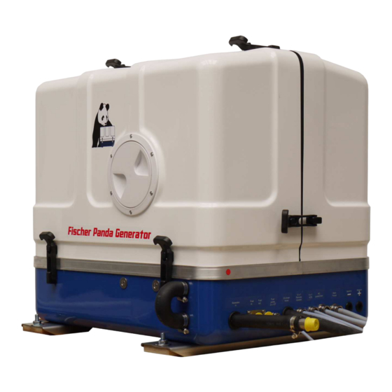
An adequate lifting yoke shall be used for transport/ Fig. 3.2-1: Lifting yoke (example) loading Scope of delivery The Fischer Panda PMS generator system contains following components: 3.3.1 Asyncron Genertoren: Fischer Panda Generator Fig. 3.3-1: Fischer Panda Generator representative picture Remote control panel Fig. - Page 32 Control Box is not required for this generators. representative picture Fischer Panda Manual Fig. 3.3.1-4: Fischer Panda Manual The Fischer Panda Manual contains following compon- ents: - Clear foil bag with general informations ect. - Generator manualwith added remote control panel manual - Spare part catalog „Installation &...
-
Page 33: Opening The Mpl Sound Insulation Capsule
3.3.2 Opening the MPL sound insulation capsule . To open the sound insulation capsule, the closures must Fig. 3.3-1: Sound insulation capsule, side part be rotated roughly 180° counter-clockwise. Use a fl at head screwdriver. Pull the sidewalls out by gripping into the slots. -
Page 34: Special Maintenance Notes And Arrangements At Long Periods Of Stand Still Time Or Shutdown
GFK sound insulation capsule with lash closures Fig. 3.3-1: Lash closures To open the lash closures pull the handle in arrow direc- Fig. 3.3-2: Lash closures tion and lift the lash of the closure pin. After lifting of the lashes, the sound isolation cover upper pars can be removed. -
Page 35: Arrangements At A Short-Term Standstill
For a 24 V battery applies 23,4 V lower open-circuit voltage (battery flat) - conservation charging 26,4 V. These data relate to a battery temperature of 20-25° C. Consider the specifications of the battery manu facturer. Fischer Panda recommendation: Notice: •... -
Page 36: Arrangements For Deconservation After A Medium-Term Standstill (3 To 6 Months)
• Clean engine according to the manufacturer. • Inject engine parts and v-belt pulleys with a preserving agent. • Clean air filter housing and inject with a preserving agent. • Close suction hole and exhaust opening (e.g. with tape or end caps). •... -
Page 37: Arrangements After A Long-Term Standstill (Shutdown) / Recommissioning (More Than 6 Months)
engine during the stand still. At the control unit a correspondent note „NO COOLING WATER“ has to be placed. • Drain engine oil as required. Refill engine with conservation oil up to maximum at the oil dip stick. • Drain diesel fuel from tank and refill with conservation mixture (90% diesel and 10% conservation oil - up to max). Let engine run for 10 min. - Page 38 • Keep shut-off lever at generator in 0-position and activate starter for approx. 10 sec. Make a break for 10 sec. and repeat procedure twice. • Visual inspection of the generator according to initial operation and start generator. Fischer Panda recommendation: Notice: After a long-term standstill a complete 150 h inspection according to inspection schedule should be carried out.
-
Page 39: The Panda Generator
The Panda Generator 4. The Panda Generator Type plate at the Generator Fig. 4.1-1: Type plate Fig. 4.1-2: Discription type plate 11.3.11 Panda_8000NE-10000NE_PMS_eng.R02 - Kapitel/Chapter 4: The Panda Generator Seite/Page 39... -
Page 40: Description Of The Generator
The Panda Generator 4.2 Description of the Generator 4.2.1 Right Side View Fig. 4.2.1-1: Right Side View Water-cooled exhaust manifold Injector for cooling water DC-alternator Engine oil filter Exhaust manifold thermo-switch Starter V-belt for DC-alternator and cooling water pump Generator power terminal box Magnetic switch for starter motor Connection for external cooling water expansion tank Generator housing with winding... -
Page 41: Left Side View
The Panda Generator 4.2.2 Left Side View Fig. 4.2.2-1: Left Side View 01) Charge control for DC-alternator 09) Seawater pump 02) Air suction housing with air filter 10) Oil dipstick 03) Actuator for speed control 11) Fuel fine filter 04) Generator housing with winding 12) Connection for external ventilation valve 05) Cooling water connection block 13) Relays... -
Page 42: Font View
The Panda Generator 4.2.3 Font View Fig. 4.2.3-1: Front View 02) Fuel solenoid valve 12) Fuel intake connection 03) Pulley for internal cooling water pump 13) Fuel backflow connection 04) Seawater pump 14) Fuel pump cable (2x1,5mm²) 05) Fuel fine filter 15) Oil drain hose 06) Ventilation screw thermostat housing 16) Remote control panel cable (12x1mm²) -
Page 43: Back View
The Panda Generator 4.2.4 Back View Fig. 4.2.4-1: Back View 01. Exhaust manifolf thermo-switch 06) Cooling water connection block 02) Air suction housing with air filter 07) Intake external cooling water expansion tank 03) Charge control for DC-alternator 08) Backflow external cooling water expansion tank 04) Generator front plate 09) Sound cover base part 05) Cooling plate... -
Page 44: View From Above
The Panda Generator 4.2.5 View from above Fig. 4.2.5-1: View from above 01) Water cooled exhaust manifold 06) Charge control for DC-alternator 02) Exhaust manifold thermo-switch 07) DC-alternator 03) Engine oil filler neck 08) Thermostat housing with thermostat set 04) Air suction housing with air filter 09) Injection nozzle 05) Cylinder head thermo-switch 10) Fuel solenoid valve... -
Page 45: Details Of Functional Units
The Panda Generator Details of functional units 4.3.1 Control panel The control panel is fitted with various monitoring functions, which increase functional reliability and operating safety of the generator. Various parts of the generator are monitored with sensors which, when triggered, generate an error message and can shut down generator operation under certain circumstances to prevent damage. -
Page 46: Cooling System - Schema
The Panda Generator 4.3.2 Cooling system - schema Fig. 4.3.2-1: Cooling System (Raw Water) - schema Seite/Page 46 Panda_8000NE-10000NE_PMS_eng.R02 - Kapitel/Chapter 4: The Panda Generator 11.3.11... -
Page 47: Fuel And Air System - Schema
The Panda Generator 4.3.3 Fuel and air system - schema Fig. 4.3.3-1: Fuel System - schema 11.3.11 Panda_8000NE-10000NE_PMS_eng.R02 - Kapitel/Chapter 4: The Panda Generator Seite/Page 47... -
Page 48: Electrical Connection - Schema
The Panda Generator 4.3.4 Electrical connection - schema see also wiring diagram Fig. 4.3.4-1: Electrical connection - schema Seite/Page 48 Panda_8000NE-10000NE_PMS_eng.R02 - Kapitel/Chapter 4: The Panda Generator 11.3.11... -
Page 49: The Operation Surveillance System
The Panda Generator 4.3.5 The Operation Surveillance System Thermo-switch at cylinder head Fig. 4.3.5-1: Thermo-switch at Cylinder Head The thermo-switch at the cylinder head serves to monitor the generator temperature. All thermo-switches for the genera- tors from Panda 6.000 upward are two-pole (earthed), so cal- led "openers". - Page 50 The Panda Generator Thermo-switch in the generator Fig. 4.3.5-4: Thermo-switch in the generator winding winding 1. Generator winding 2. Thermo-switch 3. Housing Two thermo-switches inside the windings to protect the gene- rator winding, which for safety reasons are installed indepen- dently in parallel.
-
Page 51: Lubrication Oil - Schema
The Panda Generator 4.3.6 Lubrication oil - schema Fig. 4.3.6-1: Lubrication oil - schema 11.3.11 Panda_8000NE-10000NE_PMS_eng.R02 - Kapitel/Chapter 4: The Panda Generator Seite/Page 51... -
Page 52: Remote Control Panel - See Separate Control Panel Manual
The Panda Generator 4.4 Remote Control Panel - see separate Control Panel Manual 4.4.1 Starting the Generator - see separate Control Panel Manual 4.4.2 Stopping the Generator - see separate Control Panel Manual Seite/Page 52 Panda_8000NE-10000NE_PMS_eng.R02 - Kapitel/Chapter 4: The Panda Generator 11.3.11... -
Page 53: Installation Instructions
Damages caused by faulty or incorrect installation are not covered by the warranty. Personal requirements The described instrallation must be done by a technical trained person or a Fischer Panda service point. 5.1.1 Hazard notes for the installation see “Safety instructions - Safety first!” on Page 18. - Page 54 Installation Instructions -Warning!: Danger of fire Oil and fuel vapours can ignite on contact with ignition sources. Therfore: - No open flames during work on the generator. - Do not smoke. - Remove oil and fuel residues from the generator and floor. Danger!: Danger of poisoning Contact with engine oil, antifreeze and fuel can result in .
-
Page 55: Preparing The Base - Placement
Installation Instructions Preparing the base - Placement Since Panda generators have extremely compact dimensions, they can be installed in tight locations. Attempts are sometimes made to install them in almost inaccessible places. Please consider that even almost maintenance-free machinery must still remain accessible at least at the front (drive belt, water pump) and the service-side (actuator, dipstick). -
Page 56: Installation Of The Cooling System - Raw Water
Installation Instructions 5.4 Installation of the cooling system - raw water 5.4.1 General Information The genset should have its own raw water (coolant water) inlet and should not be connected to any other engine systems. Ensure that the following installation instructions are complied with: For the avoidance of galvanic corrosion, refer to the chapter "Service instruction for marine generators (corrosion protection)". -
Page 57: Generator Installation Above Waterline
A repair is then very expensive. Replacement impeller and also a spare pump should always be on board. The old pump can be sent back to Fischer Panda. Installation above water level Fig. 5.4.4-1: Installing the generator above the water level 1. -
Page 58: Generator Installation Below Water-Line
Installation Instructions 5.4.5 Generator Installation below Water-Line If the generator cannot be attached at least 600 mm above the waterline, a vent valve must be installed at the raw water line. Possible heeling must be taken into consideration if installed Fig. -
Page 59: Generator Housing Cooled By Raw Water
Installation Instructions ...and bend it upwards. Fig. 5.4.5-3: Connection Vent Valve Both hose ends must be led out outside of the sound cover to one point, if possible 600 mm over the waterline at the mid- ships line. The valve is connected at the highest place with the two hose ends. -
Page 60: Indirect Cooling Of The Genset Housing (By The Heat Exchanger)
Installation Instructions 5.4.7 Indirect Cooling of the Genset Housing (by the Heat Exchanger) Fig. 5.4.7-1: Installation Scheme Indirect Cooling of teh Genset Housing 1. Vent valve 5. Raw water filter 2. Exhaust manifold 6. Water cock 3. Raw water pump (Raw water impeller pump) 7. -
Page 61: Ventilating At The First Filling Of The Internal Cooling Water Circuit
Installation Instructions ATTENTION! The external cooling water expansion tank may be filled only up to the lower edge of the lower tension tape (see note "max") in the maximum filling level in cold condition. 5.5.2 Ventilating at the first filling of the Internal Cooling Water Circuit Expansion Tank Fig. -
Page 62: Pressure Test For Controlling The Cooling Water Circuit
Installation Instructions 6. Close the vent screws. 7. Fill up the expansion tank. 8. Close the expansion tank. 9. Re-ventilating process 10 Operating hours after the first start-up (and if necessary) Also after the first implementing a small amount of air can be reside in the cooling circuit. To ensure an ima- culate und actual operating of the cooling system the ventilating process must be repeated casual in the next few days (weeks, if necessary). -
Page 63: Scheme For Freshwater Circuit At Two Circuit Cooling System
Installation Instructions 5.5.4 Scheme for Freshwater Circuit at Two Circuit Cooling System Fig. 5.5.4-1: Scheme for Freshwater Circuit at Two Circuit Cooling System 1. Expansion Tank 4. Freshwater pump 2. Exhaust Manifold 5. Heat Exchanger 3. Thermostat Housing 6. Cooling Water Connection Block 11.3.11 Panda PMS 8.000 NE - 42 NE Manual.R05 - Kapitel/Chapter 5: Installation Instructions Seite/Page 63... -
Page 64: Installation Of The Water Cooled Exhaust System
Installation Instructions 5.6 Installation of the water cooled exhaust system 5.6.1 Installation of the standard exhaust system The generator exhaust system must remain completely independent and separate from the exhaust system of any other unit(s) on board. The exhaust hose has an inner diameter of 30 mm. The water lock must be installed at the lowest point of the exhaust system. -
Page 65: Possible Cause: Exhaust Duct
Installation Instructions get into the engine. Thereby, the position of the generator and the water collector, as well as the arrangement of the coolant and exhaust ducts plays the decisive role. If the water collector is arranged in an unfavourable position, the coolant flowing back in the exhaust duct can rise so high, that it reaches the exhaust stack. -
Page 66: The Volume Of The Exhaust Water Collector
Installation Instructions The deeper the water collector is located underneath the generator, the better the protection from entering water into the combustion chamber. The pictures below, the distance between the critical point at the exhaust elbow and the maximum permissible water level in the exhaust duct is stated with 600 mm. - Page 67 Installation Instructions Fig. 5.6.5.1-1: Volume of the exhaust water collector If there are any doubts, a verifiction can easily be made by temporarily using a clear-sighted hose as exhaust hose. In that way, the coolant level can be checked very easily. Fig.
-
Page 68: Position Of The Water Collector
Installation Instructions 5.6.5.2 Position of the water collector Important Note! The ideal position of the water collector would be in center underneath the generator. Only in this position it is assured that the water level can not change drastically in tilted position by the water collector moving out of the center line. - Page 69 Installation Instructions Tilted position 30 degrees Fig. 5.6.5.2-3: Tilted position 30 degrees The distance of the water level, even in ideal position, chan- ges in a way that only 458 mm distance remain. So the criti- cal distance is under-run already. Tilted position 45 degrees Fig.
-
Page 70: Example Of The Installation Of The Water Collector Off-Center And Possible Effects
Installation Instructions 5.6.5.3 Example of the installation of the water collector off-center and possible effects: The following pictures are primarily relevant for an installation of the generator with the water collector on sailing yachts. A change in the mounting position caused by tilted position does not have to be reckoned concerning motor yachts. - Page 71 Installation Instructions Tilted position 30 degreed Fig. 5.6.5.3-3: Tilted position 30 degreed The distance between the hydrostatic head and the critical point at the exhaust elbow is only 216 mm. This means that in a tilted position of 30 degrees you already face the highest risk of sea water sloshing into the combustion chamber.
-
Page 72: Exhaust / Water Separator
In order to reduce the noise level of the generator unit to a minimum, an optional exhaust outlet muffler can be mounted next to the thru-hull fitting. Additionally there is a component at Fischer Panda, which acts as both an "exhaust goose neck", and water separator. - Page 73 Installation Instructions Water flow exhaust water Separator Fig. 5.6.6-1: Water Flow Exhaust Water Separator The water flow on the exhaust/water separator unit has an inner diameter (ID) of 30 mm. If the path from the water sepa- rator to the raw water outlet is very short, the hose can be fur- ther reduced to 1"...
-
Page 74: Installation Exhaust Water Separator
Installation Instructions 5.6.7 Installation exhaust water separator Fig. 5.6.7-1: Installation Exhaust Water Separator 1. Generator 4. Silencer 2. Silencer / Water lock 5. Sea cock 3. Exhaust-Water-Separator 6. Hull outlet If the exhaust water separator was sufficiently highly installed, a goose neck is no longer necessary. The exhaust/ water separator fulfils the same function. - Page 75 Installation Instructions Fig. 5.6.7-2: Expample for an unfavourable Installation Example of an unfavourable installation: - Water lock not far enough below the lowest level of the generator - Distance water lock to exhaust/water separator too large 11.3.11 Panda PMS 8.000 NE - 42 NE Manual.R05 - Kapitel/Chapter 5: Installation Instructions Seite/Page 75...
-
Page 76: Installation Of The Fuel System
Installation Instructions 5.7 Installation of the fuel system 5.7.1 General references Inside the generator capsule itself, there is the fuel filter installed (exception: Panda 4200 and 4500). Additional fuel filters (with water separator) must be mounted outside the capsule in easily accessible places in the fuel lines bet- ween the tank intake fuel pump and the diesel motor's fuel pump. -
Page 77: The Electrical Fuel Pump
Installation Instructions 5.7.2 The Electrical Fuel Pump Electrical fuel pump Fig. 5.7.2-1: Electrical Fuel Pump With the Panda generator is usually supplied an external, electrical fuel pump (DC). The fuel pump must be installed close at the fuel tank. The electrical connections are pre- loaded at the generator with the lead planned. -
Page 78: Position Of The Pre-Filter With Water Separator
Installation Instructions 5.7.4 Position of the pre-filter with water separator Additionally to the standard fine filter a pre-filter with water Fig. 5.7.4-1: Pre-filter with water separator separator must be installed outside of the sound insulation capsule in the fuel system line (not included in the delivery). 5.7.5 Ventilating air from the fuel system Normally, the fuel system is designed to vent air itself i.e. -
Page 79: Generator Dc System Installation
Installation Instructions Vent Screw at the fuel stop solenoid valve Fig. 5.7.5-1: Vent Screw at the Fuel Stop Solenoid Valve Not installed at all models! Generator DC system installation The Panda generators from 6.500 NE upwards have their own dynamo to charge a DC starter battery. It is recommended to install an additional starter battery for the generator. - Page 80 Installation Instructions NOTE: To avoid large voltage drops the battery should be installed as near as possible to the generator. The positive terminal of the battery is attached at the red cable, the negative pole at the blue cable. It must be guaranteed that first the cables are attached at the A t t e n t i o n ! : C o n s i d e r c o r r e c t c o n n e c t i o n generator and then at the battery.
- Page 81 Installation Instructions Negative battery cable Fig. 5.8.1-2: Negative Battery Cable The negative (-) battery cable is connected to the engine foot. Note! The battery negative pole may not be connected with the boat ground or with the protective grounding of the 120 V installation! DC-Relay Fig.
-
Page 82: Connection Of The Remote Control Panel - See Separate Control Panel Manual
Installation Instructions Fig. 5.8.1-5: Battery installation - Scheme 1. Generator 3. Fuse 2. Battery block 4. Battery main switch 5.8.2 Connection of the remote control panel - see separate control panel manual Seite/Page 82 Panda PMS 8.000 NE - 42 NE Manual.R05 - Kapitel/Chapter 5: Installation Instructions 11.3.11... -
Page 83: Generator Ac System Installation
Installation Instructions Generator AC System Installation ATTENTION! Before the electrical system is installed, READ the SAFETY INSTRUCTIONS of this manual FIRST! Be sure that all electrical installations (including all safety systems) comply with all required regulations of the regional authorities. This includes lightening conductor, personal protection switch etc. -
Page 84: Installation Ac-Box / Distribution Panel Separate Connected
Installation Instructions 5.9.2 Installation AC-Box / distribution panel separate connected Fig. 5.9.2-1: Installation AC-Box / distribution panel separate connected 1. Generator 3. Distribution panel 2. AC-Control Box A power source selector switch must be installed between the generator (or if applicable, AC-Control box) and the ship's electrical supply system. - Page 85 Installation Instructions generator housing and ground (in the AC-Control box) must be disconnected. Once such a ground protection cable is installed, it must be connected to the ground straps of all on board electrical devices. In order to monitor the electrical system, it is recommended to install a voltmeter (and, if possible, a current meter) down line from the power source selector switch so that all respective power sources can be monitored.
-
Page 86: Ac-Control Box With Vcs And Asb - Not All Models
Installation Instructions 5.9.3 AC-Control Box with VCS and ASB - not all models The required capacitors for the excitation of the generator are located in the AC-Control box, as well as the electro- nic control for voltage/speed regulation (VCS) and the starting current re-inforcement (ASB). The AC-Control box must be connected by electrical wires (high voltage and low-voltage) to the generator. -
Page 87: Vcs Voltage Control
Installation Instructions 5.9.4 VCS voltage control All Panda generators from Panda 8000 upwards are fitted with the electronic voltage control "VCS" as standard. The VCS controls the generator voltage and motor speed. A actuator on the injection pump can increase the engine speed by up to 8%. -
Page 88: Alternative Mini Vcs
Installation Instructions 5.9.4.1 Alternative Mini VCS Alternative for generators without AC control box the Mini VCS. The Mini VCS and the capacitators are is mounted at the generator. Mini VCS at the Panda 6500 NE PMS Fig. 5.9.4.1-1: Mini VCS at the Panda 6000 ND PMS Capacitors at the Panda 6500 NE PMS Fig. -
Page 89: Installation With Mini Vcs Mounted At The Generator
Installation Instructions 5.9.5 Installation with mini VCS mounted at the generator Fig. 5.9.5-1: Installation with mini VCS mounted at the generator 1. Generator 2. Distribution panel All electrical safety installations have to be made on board. 5.9.6 Jump start at high starting current (Booster) Additionally, the automatic start booster is located on the circuit control board. -
Page 90: Insulation Test
Installation Instructions 5.9.7 Insulation test ATTENTION: Once the electrical system installation is complete, a ground insulation test must be performed as follows: 1.) Switch off all on-board electrical devices. 2.) Start the generator. 3.) Measure the AC-voltage with a voltmeter (adjust to Volt/AC) between a) generator housing and AC-Control box b) generator housing and ground. -
Page 91: Maintenance Instructions
6. Maintenance Instructions Personal requirements All maintenance work - if not specially marked - can be made by the trained persons. Further maintenance work must only be made by Technical personel or Fischer Panda service points. Hazard notes for this chapter Notice!: see “Safety instructions - Safety first!”... - Page 92 Maintenance Instructions Danger!: Danger of poisoning Contact with engine oil, antifreeze and fuel can result in damage to health. Therefor : - Avoid skin contact with engine oil, fuel and antifreeze. - Remove oil and fuel splashes and antifreeze from the skin immediatlly. - Do not inhale oil and fuel vapours.
-
Page 93: Environmental Protection
Maintenance Instructions Environmental protection Environmental protection. Danger to the environment due to mishandling! Significant environmental damage can occur, particularly for incorrect dispo- sal, if environmentally hazardous operating materials are mishandled. The- refore: – Always observe the instructions mentioned below. – Take immediate action if environmentally hazardous materials reach the environment. - Page 94 Maintenance Instructions You require: paper towels / cloth for the oildipstick The generator must be placed at level. - with vehicular generators: Place the vehicle on a leveled surface. - with PSC generators: Place the generator on a leveled surface. - with marine generators: Measure the oil-level when the ship is not lop-sided.
-
Page 95: Refilling Oil
In that case, we recommend going to a shop or a Fischer Panda servicepoint. - if the oil is cloudy or even „creamy“, coolant might have mixed with the oil. See a garage or a Fischer Panda ser- vicepint immediately. -
Page 96: Replacement Of Engine Oil And Engine Oil Filter
Maintenance Instructions 6.6 Replacement of engine oil and engine oil filter You require: - Engine oil. See attachment. - New oil filter (not with generators with EA300 engines) - Sealings for oil drain screw - Personal protective gear - Container to collect used oil (heat resistant and of sufficient size) - Open-ended wrench for oil drain screw - Paper towels and cloth... - Page 97 Maintenance Instructions 2. Loosen oil filling cap Fig. 6.6-1: Oil filling cap Unscrew the oil filling cap. This is necessary, because otherwise a vacuum will form and the oil can not comple- tely drain off. Sample picture 3. Open oil drain screw. Fig.
-
Page 98: After The Oil Change
Maintenance Instructions Oil screen with generators with EA300 engines Fig. 6.6-4: Oil screen The oil screen should be cleaned every 500 operating hours: to do so follow the instructions in the engine manual. Use spanner size 17mm. Sample picture 6. Preparing a new filte Fig. -
Page 99: Verifying The Starter Batterie And (If Necessary) The Battery Bank
Maintenance Instructions Verifying the starter batterie and (if necessary) the battery bank Check the condition of the battery. Proceed here as prescribed by the battery manufacturer. If from the battery manufakturer not otherwise mentioned 6.7.1 Battery 6.7.1.1 Check battery and cable connections •... -
Page 100: Grease Lubricated Generator Backend Bearing
Maintenance Instructions • Measure the electrolyte density of individual cells with a Fig. 6.7.1-1: Battery commercial hydrometer. The hydrometer reading (see table on following page) indicates the battery’s state of charge. During measurement, the temperature of the electrolyte should preferably be 20 °C. Electrolyte density in [kg/ l] Charge status... -
Page 101: Exchange Of Grease Lubricated Bearing
Maintenance Instructions Grease lubricated backend bearing with cooling disc. Fig. 6.8-2: Grease lubricated backend bearing Sample Picture 6.8.1 Exchange of grease lubricated bearing Only special trained persons are allowed to do this STOP! maintenance! Warning!: Automatic start DANGER FOR LIFE! - Inappropriate handling can lead to health damages and death. -
Page 102: Installing The New Backend Bearing
Sample picture Note: If there is no suitable extractor available, a suitable extractor can be purchased from Fischer Panda. Check the O-ring seal which is mounted in the bearing cover and replaced if damaged. 6.8.1.3 Installing the new backend bearing Seite/Page 102 Panda PMS 8.000 NE - 42 NE Manual.R05 - Kapitel/Chapter 6: Maintenance Instructions... - Page 103 Maintenance Instructions Mount bearing case in the generator cap. Fig. 6.8.1.3-1: 1Mount bearing cover Place bearing case loosely into the generator cap, assure with one hand against falling out. Thereby pay attention that the case is mounted in the same position as before - the previously added markings have to match again! Sample Picture...
- Page 104 Maintenance Instructions Fig. 6.8.1.3-4: ’Attach bearing case Tighten fixing bolts M8 with 22 to 25 Nm (Allen key SW6). Now carefully press the bearing case with a soft-head hammer (or a hammer plus mandrel) in its hub. Thereby relocate mandrel rotatory after each hit to avoid can- ting.
- Page 105 Maintenance Instructions With the other hand, put a screw wrench on the long nut, fasten Fig. 6.8.1.3-7: Press in ball bearing slowly. Thus the ball bearing is pressed onto the shaft. If necessary hold driving shaft with suitable wrench, to prevent diesel engine from rotation simultaneously.
-
Page 106: Checking The Oil Level Of The Generator End Bearing At Fischer Panda Generators
If your generator does not feature these control modules or if these are not accessable, please refer to your Fischer Panda distribution partner or to Fischer Panda directly. The correct oil level is at the middle of the sight glass/ sight hose. -
Page 107: Refilling Oil
2. Refill some oil by means of a small hopper or a syringe. 3. Now tighten the screw again and fasten it with 20 Nm. 6.9.3 Refiller-Set An appropriate refiller set can be purchased at Fischer Panda. The refiller set contains: Oil: Shell Omala HD220. -
Page 108: Replacement Of The Oil-Cooled Backend Bearing
Maintenance Instructions 6.10 Replacement of the oil-cooled backend bearing A bearing replacement should only be executed by a trained professional. 6.10.1 Exchange oil-cooled bearing Warning!: Automatic start DANGER TO LIFE! - Inappropriate handling can lead to health damages or death. The battery bank must always be disconnected (first negative pole, then plus pole), to ensure that the generator can not be started by accident when ope- rations at the generator itself or its electrical system shall be executed. - Page 109 Maintenance Instructions Demount the oil cap by loosening the nuts M6 (Tool: Socket Fig. 6.10.2-3: Demounting the oil cap wrench SW10). As shown, degrease the spot with a fat solvent and make a Fig. 6.10.2-4: Marking the bearing position mark with a waterproof pen. 11.3.11 Panda PMS 8.000 NE - 42 NE Manual.R05 - Kapitel/Chapter 6: Maintenance Instructions Seite/Page 109...
- Page 110 Maintenance Instructions Unscrew the fastening screws (Tool: Allen wrench SW6). Fig. 6.10.2-5: Loosen fastening screws As shown, screw in 3 lifting screws M8x50 as far as possible by Fig. 6.10.2-6: Insert lifting screws hand. Then screw in those 3 screws with a screw wrench SW13 Fig.
- Page 111 Maintenance Instructions Knocking out the ball bearing Fig. 6.10.2-8: Knocking out the ball bearing Put the bearing housing horizontally on e.g. 2 wood ledges, the ball bearing pointing downwards. Alternatively, the bearing housing can rest on the lifting screws. Place an appropriate bolt (e.g. extension of a ratch) on the inner bearing ring.
- Page 112 Maintenance Instructions Dismounted shaft sealing ring Fig. 6.10.2-11: Dismounted shaft sealing ring Remove O-rings from the bearing seat: Fig. 6.10.2-12: Remove o-rings Take both O-rings out of the bearing seat. Seite/Page 112 Panda PMS 8.000 NE - 42 NE Manual.R05 - Kapitel/Chapter 6: Maintenance Instructions 11.3.11...
- Page 113 Maintenance Instructions Remove O-ring from the oil cap. Fig. 6.10.2-13: Remove O-ring Clean the bearing seat and the oil cap. Slightly lubricate the new O-rings and mount them. Mounting the NEW shaft sealing ring: Fig. 6.10.2-14: Mounting the shaft sealing ring Lubricate/grease the shaft sealing rings’...
- Page 114 Maintenance Instructions Push the sealing ring on the mandrel, the open side should Fig. 6.10.2-16: point towards the handle. The side marked with „X“ is to be used. Mounting of the shaft sealing ring Fig. 6.10.2-17: Fitting the shaft sealing ring Correctly mounted sealing ring Fig.
- Page 115 Maintenance Instructions Clean the shaft Fig. 6.10.2-19: Cleaning the shaft Check the wheel tread for damages Fig. 6.10.2-20: Checking the wheel tread The wheel tread has to be - clean - free of partial damages (drafts, indentations, notches, scratches). Mounting the bearing housing inside the generator cap: Fig.
- Page 116 Maintenance Instructions With the other hand, loosely screw in the lifting screws for gui- Fig. 6.10.2-22: Mount the bearing housing dance. Now carefully press the bearing housing in its seat with a soft Fig. 6.10.2-23: Mount the bearing housing headed hammer (or hammer plus mandrel). By doing that, shift the mandrel after each scale in a circle to avoid canting.
- Page 117 Maintenance Instructions Mounting the ball bearing: Fig. 6.10.2-25: Mount the thread rod Screw the thread rod into the generator shafts’ tap hole as far as possible. Push the ball bearing, the pressure ladle and the washer up Fig. 6.10.2-26: Mount the ball bearing against the shaft, then screw on the hex nuts.
- Page 118 Maintenance Instructions By doing that, the ball bearing is pressed onto the shaft. Fig. 6.10.2-28: Mount the ball bearing If necessary, hold the crank shaft with an appropriate wrench to keep the diesel engine from rotating concurrently. Press the ball bearing on as far as possible. (Tool: Wrench SW13 and SW22) Hold up the crank shaft Fig.
- Page 119 (PAO) Grades of oil 220 to 320 Minimum requirement gear oil: CLP HC These oils are available at industrial lubricant commerces as well as Fischer Panda. * Oil change intervals every 1500 hours ** Oil change intervals every 300 hours 11.3.11...
- Page 120 Maintenance Instructions Screw in the ventialtion screw and tighten it (Tool: Allen Fig. 6.10.2-34: Screw in the ventilation screw wrench SW6 - 20 Nm). Remove the start interlock. Re-connect the starter battery. Run the generator for 3-5 minutes. Check the oil level, if necessary refill/ discharge some oil. Mount the capsule.
-
Page 121: Checking The Water Separator In The Fuel Supply
Maintenance Instructions 6.11 Checking the water separator in the fuel supply The pre-filter with water separator has a cock underneath, by which means Fig. 6.11-1: Pre-filter with water separator the water can be drained. This water sinks to the bottom, due to the difference in the densities of water and fuel. -
Page 122: Exchange Of The Fuel Filter
Maintenance Instructions 3. After pressing the failure bypass switch for approx 3 - 4 Fig. 6.11.1-2: Ventilation Screw at the fuel solenoid valve minutes the ventilation screw located at the fuel solenoid valve has to be loosened. The button must be kept pres- sed, whilst opening the screw. -
Page 123: Optional Fuel Filter With Sight Glass
Maintenance Instructions 6.11.2.1 Optional fuel filter with sight glass The filter change depends on the fuels’ degree of pollution, Fig. 6.11.2-1: Fuel filter but should be executed every 300 operating hours at the latest. 01. Fuel filter housing 02. Fuel filter element 03. -
Page 124: Replacement Of The Air Filter Mat
Maintenance Instructions Screw the new filter element into the mount. Fig. 6.11.2-4: Fuel filter Lubricate the sight glasses o-ring with a heat resistant grease (Specification: Antiseize) and screw the sight glass back into its mount (right hand rotation). 6.11.3 Replacement of the air filter mat Open the air suction housing by loosen the six screws on the housing cover. -
Page 125: Alternative Replacement Of The Air Filter Mat With Pull Out Holder
Maintenance Instructions 6.11.3.1 Alternative replacement of the air filter mat with pull out holder Air filter housing with pull out holder Fig. 6.11.3-1: Air Suction Housing with pull out holder Tip the two fasteners 90° Fig. 6.11.3-2: Air Suction Housing with pull out holder Pull the filter mat holder out Fig. -
Page 126: Ventilation Of The Coolant Circuit / Freshwater
Maintenance Instructions Replace the air filter mat Fig. 6.11.3-4: Air Suction Housing with pull out holder Assembly in reversed order of steps 1-4 6.12 Ventilation of the coolant circuit / freshwater Attention Special notes for the ventilation of the cooling system If the cooling water is drained, or if other air has entered the cooling system, it is necessary to ventilate the cooling system. - Page 127 Maintenance Instructions Open the ventilating screw above the cooling water pump Fig. 6.12.0-2: Ventilating Screw casing. Sample Picture Open the ventilating screw on the thermostat casing. Fig. 6.12.0-3: Ventilating Screw on the Thermostat Housing Sample Picture The cooling water can be filled into the External expension Fig.
-
Page 128: Replacement Of The V-Belt For The Internal Cooling Water Pump
Maintenance Instructions The ventilation screw above the cooling water pump casing Fig. 6.12.0-5: Ventilation Screw above the Cooling Water Pump may not be opened under any circumstances, while the genera- Casing tor is running. Air will be sucked through the opening, if this should happen by mistake. - Page 129 Maintenance Instructions Loosen the screw beneath the alternator Fig. 6.12.1-2: Screw beneath the Alternator Sample Picture Press the alternator in the direction of the thermostat casing Fig. 6.12.1-3: DC Alternator Exchange V-belt Sample Picture Re-tighten V-belt Fig. 6.12.1-4: Drawing belt pulley The belt pulleys should only be tightened to the extent that it can still be pushed with a thumb (approx.
-
Page 130: The Seawater Circuit
The Cooling water pump Impeller must be regarded as a wearing part. The life expectancy of an impeller can vary considerably and depends exclusively upon the operating conditions. The Fischer Panda Generator cooling pumps are designed in a way, that the speed of the pump in comparison to other generators is relatively low. This has a positive effect on the life expectancy of the pump. -
Page 131: Replacement Of The Impeller
Maintenance Instructions 6.14.1 Replacement of the impeller Close the seawater valve. Fig. 6.14.1-1: Seawater valve Sample Picture The seawater pump is located on the front side of the genset. Fig. 6.14.1-2: Seawater pump Sample Picture Remove the cover of the seawater pump by loosen the 4 wing Fig. - Page 132 Maintenance Instructions Remove the impeller from the shaft by means of multi grip Fig. 6.14.1-4: Impeller pliers. Mark the impeller, to make sure that it is in the correct position when re-installation is carried out. Sample Picture Check the impeller for damage and replace it if necessary. Fig.
-
Page 133: Generator Faults
The work described here, unless otherwise indicated, are performed by the operator. Any further repair work may be performed only by specially trained personnel or by authorized repair shops (Fischer Panda service points). This is especially for working on the valve timing, fuel injection system and the engine repair. -
Page 134: Tools And Measuring Instruments
Generator Faults Danger!: Danger of poisoning Contact with engine oil, antifreeze and fuel can result in damage to health. Therefor : - Avoid skin contact with engine oil, fuel and antifreeze. - Remove oil and fuel splashes and antifreeze from the skin immediatlly. - Do not inhale oil and fuel vapours. -
Page 135: Troubleshooting Table And Flowchart
Generator Faults Troubleshooting Table and Flowchart 7.4.1 Generator output voltage too low For 50 Hz versions: less than 200 V Cause Solution Generator is overloaded. Reduce the electrical load (switch off load) Motor is not reaching the rated rpm. Refer to "motor faults" section. Defective capacitor(s). -
Page 136: Motor Does Not Achieve Enough Speed During Starting Process
Generator Faults Cause Solution Glow-plugs not working correctly. Check glow plugs and heating time. Too much air in fuel lines. Test fuel system for leakage. Bleed air from fuel system (refer to section "Bleeding Air from Fuel System"). Fuel-filter blocked. Replace fuel filter. -
Page 137: Motor Stops By Itself
Generator Faults 7.4.11 Motor stops by itself Cause Solution Lack of fuel. Check fuel supply system. Excess heat in cooling system (thermo switch tripped)-lack of cooling Check cooling water system flow: water pump, inlet water filter, extra water. Is indicated on the remote control panel. heat exchanger coolant flow. -
Page 138: Troubleshooting Flowcharts
Generator Faults 7.4.15 Troubleshooting Flowcharts Fig. 7.4.15-1: Troubleshooting Flowchart - Page 1 Page 1 Generator Install Generator installed Before you start, please read the manual and make yourself familiar with the generator. Correct Exchange Fuse Wiring Fuse on the back Wiring correct? Generator starts Panel works... - Page 139 Generator Faults Fig. 7.4.15-2: Troubleshooting Flowchart - Page 2 Page 2 Generator runs Go to page 1 Defective load/ Restore residual Exchange cable *1 Exchange cable *1 Switch off load magnetism *1 Generator runs Residual magnetism Cable AC-out ok? Cable generator AC Box ok? Load switched on? without load - No voltage...
-
Page 140: Details And Explanations Concerning The Troubleshooting Flowchart
Generator Faults 7.4.15.1 Details and explanations concerning the troubleshooting flowchart Each failure position in the flowchart above contains a reference number. With this reference number, the corresponding work steps can be taken from the list below. 1.1 Fuse at the remote control panel. Execute the fuse exchange as indicated in the data sheet of your remote control panel. - Page 141 Repair the connection assembly. 9.1 Defective cable to the AC-Box. Get the cable to the AC-Box exchanged by a Fischer Panda Servicepoint/Service Center. Attention: Voltage up to 400V - Danger to life! The operations are to be executed by a trained professional only! 9.2 Defective cable AC out.
- Page 142 The operations are to be executed by a trained professional only! 11.4 Disrupted measuring voltage to VCS. Get the measuring voltage cable connected/exchanged by a Fischer Panda Servicepoint/Service Center. Attention: Voltage up to 400V - Danger to life! The operations are to be executed by a trained professional only! 11.5 Generator is overloaded.
- Page 143 Generator Faults 13.4 Heat exchanger blocked. Get the heat exchanger checked and repaired by a Fischer Panda Servicepoint/Service Center. 13.5 Defective temperature switch, possibly loose contact/cable break. Get the temperature switch checked and repaired by a Fischer Panda Servicepoint/Service Center.
-
Page 144: Versions Of The Generator Power Terminal Box
Generator Faults 7.5 Versions of the generator power terminal box Generator Power Terminal Box 230 V / 50Hz Fig. 7.5.0-1: Generator output terminal box 230V / 50 Hz In these terminal boxe there are the electrical connection points for the AC generator. - Page 145 Generator Faults Fig. 7.5.0-4: Wiring diagram HP3 - 400V / 50 Hz Generator Power Terminal Box 120 V / 60 Hz Fig. 7.5.0-5: Generator power terminal box 120 V / 60 Hz Z1.2 In these terminal boxe there are the electrical connection points for the AC generator.
- Page 146 Generator Faults Fig. 7.5.0-6: Wiring diagram HP1 - 120 V / 60 Hz Generator Power Terminal Box 240 V / 60 Hz (208 V / 60 Hz) Fig. 7.5.0-7: Generator power terminal box 240 V / 60 Hz In these terminal boxe there are the electrical connection points for the AC generator.
- Page 147 Generator Faults Fig. 7.5.0-8: Wiring diagram HP3 - 240 V / 60 Hz Generator Power Terminal Box DVS - 120 V + 240 V / 60 Hz Fig. 7.5.0-9: Generator power terminal box DVS 1 1 1 1 3 3 3 3 2 2 2 2 In these terminal boxe there are the electrical connection points for the AC generator.
-
Page 148: Overloading The Generator
Generator Faults Fig. 7.5.0-11: Wiring diagram DVS - 230 V + 400 V / 50 Hz 7.6 Overloading the generator Please ensure that the generator is not overloaded. This must be considered, especially with regards to multi power generators. In this case the extra load including the electrical performance can be considerably greater than the drive performance of the motor, which can eventually lead to a damaged motor. -
Page 149: Monitoring The Generator Voltage
"normally". The Fischer Panda generators are aligned that they keep these default values during normal load. With high load or overload it can occur that the voltage drops on 190 V (95 V in the 60 Hz version) and partly still more deeply. -
Page 150: Setting The Speed Governor Of The Actuator
Generator Faults 7.7 Setting the speed governor of the actuator The speed of the generator is determined by two independent settings; an upper and lower speed governor: • By means of the adjusting nuts on the spindle of the servomotor right and left from the spindle nut (Setting of the normal speed limit). -
Page 151: Setting The Normal Speed Settings
Generator Faults Speed adjustment lever Fig. 7.7.1-1: Counter nut, adjustment screw and speed adjustment 1. Counter nut 2. Adjustment screw for upper setting 3. Speed Adjustment Lever This setting should not be changed otherwise the guaranty will expire. lever 7.7.2 Setting the normal speed settings Setting the lower speed limit 1. -
Page 152: Greasing The Trapezoidal Thread Spindle On The Speed Actuator
Generator Faults 7.7.3 Greasing the trapezoidal thread spindle on the speed actuator The speed setting of the trapezoidal thread spindle must be regularly greased. Only high temperature-resistant grease (up to 100 °C) may be used. The end of the nu ts must also be smeared with grease. If the spindle has not been sufficiently greased, then it can jam. -
Page 153: Consequences Of A Continual Overloading Of The Actuator
Generator Faults 7.7.4 Consequences of a continual overloading of the Actuator If the generator is overloaded, the voltage falls under the nominal value due to insufficient engine power. The actua- tor is already at the upperst speed limit and still tries to rise the rev. speed of the engine. There is an internal control which limits the actuator current, but an overloading over a longer period of time can still damage the winding of the actuator. -
Page 154: The Following Measures Are Necessary If The Actuator Is Jammed
Generator Faults If the above test produces no result, it can be assumed that the actuator operates smoothly. The electrical groups of components must then be checked: 1. Re-connect plug. 2. Start generator. 3. Turn the actuator by hand to check whether the Spindle is reversed by the motor. 4. -
Page 155: Generator-Output Voltage Is Too Low
Generator Faults Generator-Output Voltage is too low If the AC generated is too low, then the consumers should be disconnected, one after the other, in order to reduce the load on the generator. Generally the problem is then solved. The frequency should be checked, if the output voltage is correct after the consumers have been disconnected. -
Page 156: Checking The Capacitors
Generator Faults 7.8.2 Checking the Capacitors ATTENTION! If the capacitors are to be checked, make sure that the capaci- tors has been discharged. A visual check can give information on whether the capacitors are defective: - Dielectric leak? - Did the capacitor become longer? Multimeter Fig. -
Page 157: Measuring The Ohm Resistance Of The Generator Windings
Generator Faults Both partial windings must be connected for the 60Hz Version, i.e. there must be a connection made between wire 1 and 3 (see circuit plan). (Note: The current arises from the rest magnetism of the rotor, which induces a voltage in the winding). 7.8.4 Measuring the Ohm Resistance of the Generator Windings If a short circuit could not be found by using a multi-meter, then the windings parts of the generator must be checked by means of an Ohmmeter that is suitable for low resistance values. -
Page 158: Measuring The Inductive Resistance
Generator Faults 7.8.6 Measuring the Inductive Resistance An Ohm measurement of a winding does not always give reliable information concerning the state of the winding. If there are resistance irregularities between the windings parts, this is a sure sign that the winding is defective. This means the opposite cannot be concluded. -
Page 159: Engine Starting Problems
Generator Faults 7.10 Engine Starting Problems 7.10.1 Electric Fuel Solenoid Valve The fuel solenoid valve is located in front of the injection pump. It opens automatically, if the "START"-button is pres- sed on remote control panel. If the generator is switched to "OFF", the solenoid valve closes. It takes some seconds, before the generator stops. -
Page 160: Lifting Solenoid For Motor Stop - Optional
Generator Faults This period can be reduced by pushing the button on the front of the generator. The generator can be started by means of the remote control as long as the button is depressed. The switch/ button bypasses any faults allowing the generator to run. -
Page 161: Troubleshooting Table
Generator Faults the springs, roller bearings or cog teeth. This could lead to complete destruction of the starter. It is important that every person who operates the generator is informed of this situation. This is practically the only handling error that can be made on board that can lead to fatal consequences for both generator and operator. - Page 162 Generator Faults Leere Seite / Intentionally blank Seite/Page 162 Panda PMS 8.000 NE - 42 NE Manual.R05 - 11.3.11...
-
Page 163: Tables
Tables 8. Tables Technical Data Fig. 8.1-1: Technical Data Panda 6000 ND Panda 8000 NE Panda 9000 ND Panda 1000NE Panda 12000 NE Type Z482 Z482 D722 Z602 D722 Govenor MIni VCS mechanisch Automatic startbooster nein nein Cylinder Bore 67mm... - Page 164 Tables Panda 14000 NE Panda 15000NE Panda 18 NE Panda 24 NE Panda 30 NE Permissible max. permanent tilt of engine a) 25° crosswise to the longitudinal axis b) 20° in longitudinal direction ² progressive speed by VCS ³ 0,35l/kW electrical power, the randomized values between 30% and 80% of the rated speed Fig.
-
Page 165: Rated Current
Tables Panda 30/4 Panda 40/4 Panda 50/4 Cooling water requirement for seawater 40-50l/min 40-50l/min 40-50l/min circuit (Marine generators only) Permissible max. permanent tilt of engine a) 25° crosswise to the longitudinal axis b) 20° in longitudinal direction ² progressive speed by VCS ³... -
Page 166: Engine Oil
API CDEngine oil for suction- and turbo diesel engine API CFReplace the specification API CD since 1994 API CGEngine oil for highest demands, turbo-tested For the Fischer Panda Generator the API CF Oil is needed. Engine oil type over 25°C... -
Page 167: Coolant Specifications
Use a mixture of water and antifreeze. The antifreeze needs to be suitable for aluminium. The antifreeze concentra- tion must be regularly checked in the interests of safety. Fischer Panda recommend to use the product: GLYSANTIN PROTECT PLUS/G 48 Engine coolant automotive industry Product description Product name GLYSANTIN ®... -
Page 168: Hp1 - 120V / 60 Hz
Tables Fig. 8.7.1-1: HP1 - 230V / 50 Hz 8.7.2 HP1 - 120V / 60 Hz Fig. 8.7.2-1: HP1 - 120V / 60 Hz 8.7.3 HP3 - 400V / 50 Hz Fig. 8.7.3-1: HP3 - 400V / 50 Hz 8.7.4 HP3 - 120V / 60 Hz Seite/Page 168 Panda PMS 8.000 NE - 42 NE Manual.R05 - Kapitel/Chapter 8: Tables 11.3.11... -
Page 169: Dvs - 400V / 50 Hz
Tables Fig. 8.7.4-1: HP3 - 120V / 60 Hz 8.7.5 DVS - 400V / 50 Hz Fig. 8.7.5-1: DVS - 400V / 50 Hz 11.3.11 Panda PMS 8.000 NE - 42 NE Manual.R05 - Kapitel/Chapter 8: Tables Seite/Page 169... -
Page 170: Dvs - 120V 240V / 60 Hz
Tables 8.7.6 DVS - 120V 240V / 60 Hz Fig. 8.7.6-1: DVS - 120V 240V / 60 Hz 8.8 Resistor & inductance of the generator coil Fig. 8.8-1: Resistor + inductance generator coil HP1 L-N[Ohm] L-Z[Ohm] L-N[Ohm] L-Z[Ohm] Mains 120V / 60Hz Mains 120V / 60Hz Panda 8000... -
Page 171: Voltage Values Stator Coil
~ 2-3 Volt ~ 3-4 Volt ~ 3-5 Volt ~ 3-5 Volt If your generator is not mentioned, ask your local Fischer Panda Dealer for the technical datas coil. 8.10 Diameter of conduits Fig. 8.10-1: Diameter of conduits Generator type Ø... - Page 172 Tables Generator type Ø Cooling water conduit Ø Exhaust conduit Ø Fuel conduit [mm] Freshwater Seawater Supply Return [mm] [mm] [mm] [mm] Panda PMS 30 NE Panda PMS 33 KU Panda PMS 42 KU Panda PMS 32 YA Panda PMS 50 YA Panda PMS 60 YA Panda PMS 50 MB Panda PMS 60 MB...
-
Page 173: Impellerfilter
Impellerfilter Fischer Panda Datasheet 9. Impellerfilter Art Nr. 31.06.03.003P Bez. Impellerfilter for Marine Panda P6, P8, P9, P10, P12 and since March 2007 Dokument Hardware Software Aktuell: R2 04.05.07 12.04.07 -------------------------- Replace: V1 12.04.07 -------------------------- Tested for a flow rate up to 22l/min 31.06.03.003P_Kunde_Impellersieb_Panda_6,8,9,10,12,14_PMS_eng.fm... -
Page 174: General
Fischer Panda Datasheet 9.1 General Starting with March 2007 the Fischer Panda generators type 6, 8, 9, 10, 12 and 14 has got an extra impellerfilter. 9.2 How it works When the impeller breaks, pieces of rubber will penetrate into the cooling system. This pieces can stock in the pipes with lower diameter (such as the heat exchanger) and reduce the cooling water flow. - Page 175 Impellerfilter Fischer Panda Datasheet Impellerfilter. The impellerfilter is mounted at the right front motor- base. Fig. 9.3-1: Impellerfilter Loose holding screw. Loose the holding srew two turns. Srew M6 (*SW 10) *SW 10 = wrench size 10mm Fig. 9.3-2: Holding screw First hose clamp.
- Page 176 Impellerfilter Fischer Panda Datasheet Second hose clamp. Loose the second hose clamp. Use a srew driver, or better a wrench SW 7mm. Fig. 9.3-4: Second hose clamp Remove the cooling water hose. remove the first cooling water hose. Some raw water may flow out of the hose or the impellerfilter.
- Page 177 Impellerfilter Fischer Panda Datasheet Pull the Impellerfilter out of the capsule. The second cooling water hose can be removed within these procedure. Some raw water may flow out of the hose or the impellerfilter. The hose can be closed with the cap you get toge- ther with the impellerfilter spare part pack.
-
Page 178: Spare Part Kit
Impellerfilter Fischer Panda Datasheet 9.4 Spare part kit Fischer Panda Art Nr. 21.03.02.005S Impellerfilter Art. No. 31.06.03.003P Screw M6x10 Art. No. G3A20093306010 with spring ring Art.No. G3A20012706 cap 19mm (2x) Art.No. PMGPN610U19 Fig. 9.4-1: Spare part kit Page/Seite 178 - Kapitel 9: Impellerfilter... -
Page 179: Dimensions
Impellerfilter Fischer Panda Datasheet Dimensions Fig. 9.5-1: Dimensions 31.06.03.003P_Kunde_Impellersieb_Panda_6,8,9,10,12,14_PMS_eng.fm Kapitel 9: Impellerfilter - Page/Seite 179... - Page 180 Impellerfilter Fischer Panda Datasheet Intentionally Blank Page/Seite 180 - Kapitel 9: Impellerfilter 31.06.03.003P_Kunde_Impellersieb_Panda_6,8,9,10,12,14_PMS_eng.fm...
-
Page 181: Generator Control Panel P6
Power - wherever you are Manual Generator Control Panel P6+ 12V version - 21.02.02.046H 24V special version - 21.02.02.047H Option automatic adapter - 21.02.02.016H Option master-slave adapter - 21.02.02.015H Fischer Panda GmbH Panel Generator Control P6+ RE0703_Kunde_eng.R06.1 11.3.11... -
Page 182: Current Revision Status P6+ Manual
Duplication and change of the manual is permitted only in consultation with the manufacturer! Fischer Panda GmbH, 33104 Paderborn, reserves all rights regarding text and graphics. Details are given to the best of our knowledge. No liability is accepted for correctness. Technical modifications for improving the product wit- hout previous notice may be undertaken without notice. -
Page 183: Safety Instructions Generator Control P6
10.1 Personal requirements The settings described here can by performed by the operator, unless otherwise indicated. The installation should be carried out by specially trained personnel or by authorized repair shops (Fischer Panda service points). 10.2 Safety instructions for this chapter Note!: Follow the general safety instruction at the front of this manual. - Page 184 Safety Instructions Generator Control P6+ Note!: Note also the safety of the other components of your system. Seite/Page 184 Panel Generator Control P6+ RE0703_Kunde_eng.R06.1 - Kapitel/Chapter 10: Safety Instructions Generator Control P6+ 11.3.11...
-
Page 185: General Operation
14. Push button panel „off“ 07. LED for battery charge voltage fault green/red 15. Push button panel „on“ Fischer Panda Art. No. 21.02.02.009H LED green: normal operation mode, LED red: fault, LED yellow: warning, LED orange: active 11.3.11 Panel Generator Control P6+ RE0703_Kunde_eng.R06.1 - Kapitel/Chapter 11: General operation... -
Page 186: Rear View 12V-Version
02. Terminal block (master-slave adapter: left row; automatic adapter: right row) 03. Terminals 1-12 (see Kapitel 11.4.2, “Terminal connections,” auf Seite 188) 04. Fuse 630mA slow-blow Fischer Panda Art. No. 21.02.02.009H Seite/Page 186 Panel Generator Control P6+ RE0703_Kunde_eng.R06.1 - Kapitel/Chapter 11: General operation... -
Page 187: Rear View 24V-Version
03. Fuse 630mA slow-blow 04. Terminals 1-12 (see Kapitel 11.4.2, “Terminal connections,” auf Seite 188) 05. Linear controller 24V 06. Linear controller 24V Fischer Panda Art. No. 21.02.02.012H 11.3.11 Panel Generator Control P6+ RE0703_Kunde_eng.R06.1 - Kapitel/Chapter 11: General operation Seite/Page 187... -
Page 188: Installation Of The Remote Control Panel
General operation 11.4 Installation of the remote control panel 11.4.1 Placement. Install the remote control panel at a dry, good accessible and shady place. Connect the remote control panel to the standard 12 core cable at the generator. (1:1) 11.4.2 Terminal connections Standard for NC temperature switch configured i.e. -
Page 189: Function Of The Jumpers
General operation AC-Fault (Fuel Error generator AC input for NC-open-collector-sensor-switch to GND (N = no error). The input ≥ Level) [former T- loads the switch with 2,5mA to +12V. (with 24V-operated internally generated). The occurrence Oil] of an error is delayed, for analysis and displayed, around 100ms. Omission not. The input status is indicated with red LED. - Page 190 General operation J209 DC-Control-Signal (-) = OK dynamo 12V at Kubota Z 482 / D 722 engines DC-Control-Signal (+) = OK three-phase DC-alternator ≥ J210 closed Input AC-Fault has Pull-Up-current 10mA ≥ open Input AC-Fault has Pull-Up-current 2,5mA The solder jumpers are marked on the printed circuit board (with jumper no. and at three-part solder jumper with soldering surface no.) (1): Equivalent resistance for load control lamp e.g.
-
Page 191: Configuration And Adjustment
General operation 11.4.4 Configuration and adjustment 11.4.4.1 Configuration and setting sheet KE01 Standard jumpering for generators with three-phase DC-alternator (Kubota Super 5 series). Panel only for 12V-operation. The safety device is installed with the value 0,63AT. The circuit parts for 24V-operation are not equipped. Fig. -
Page 192: Configuration And Setting Sheet Ke02
General operation 11.4.4.2 Configuration and setting sheet KE02 Standard jumpering for generators with three-phase DC-alternator. Panel for 24V-operation (over attitude of solder jumper J101 alternatively 12V-operation is possible). The safety device is installed with the value 0,63AT. The circuit parts for 24V-operation are not equipped. Fig. -
Page 193: Configuration And Setting Sheet Ke03
General operation 11.4.4.3 Configuration and setting sheet KE03 Standard jumpering for generators with DC-alternator. Panel only for 12V-operation. The safety device is installed with the value 0,63AT. The circuit parts for 24V-operation are not equipped. Fig. 11.4.4.3-1: Einstellung der Lötjumper für diese Konfiguration (Spalte Konf.) Jumper Status Konf. -
Page 194: Configuration And Setting Sheet Ke04
General operation 11.4.4.4 Configuration and setting sheet KE04 Standard jumpering for generators with DC-alternator. Panel for 24V-operation (over attitude of solder jumper J101 alternatively 12V-operation is possible). The safety device is installed with the value 0,63AT. The circuit parts for 24V-operation are not equipped. Fig. -
Page 195: Starting Preparation / Checks (Daily)
General operation 11.5 Starting preparation / Checks (daily) 11.5.1 Marine version 1. Oil level control (ideal level: 2/3 MAX). The level should be about 2/3 of the maximum level of a cold engine. Further, if installed, the oil level of the oil-cooled bearing must be controlled before each start - see sediment bowl at generator front cover!. -
Page 196: Starting And Stopping The Generators
General operation 11.6 Starting and stopping the generators 11.6.1 Starting the generator Warning!: Automatic start Danger for life! - The generator can be equipped with a automa- tik start device. This means the generator can be started by an external signal. To avoid an unexpected starting of the genera- tor, the starter battery must be disconected before start wor- king at the generator. -
Page 197: Stopping The Generator
General operation Attention!: In the event of starting problems, close the sea water inlet cock. Panda marine generators only. Should there be any reason to turn the engine (over) or start the engine i.e. to bleed the fuel system, the sea water inlet cock must be closed! During the starting process, the cooling water pump is driven with the motor. -
Page 198: Automatic Adapter - Optional
01. Main terminals 02. Automatic adapter 21.02.02.016H 03. 8-pole DIP-switch Fischer Panda Art. No. 21.02.02.016H 11.7.1 Function: The automatic adapter RE0704 extends the generator control panel P6+ with an automatic input. A potential-free contact can be attached to this input. If this contact is closed, then the generator, which is attached to the generator control panel P6+, is started automatically. - Page 199 General operation With (+) characterized connection is the input. The input is connected through a resistance to 12V (with 24V-operated internally generated). If the two connections are short circuited over a potential-free contact, then the input current flows. To be considered for an electronic contact the low input current and the polarity is to be selected. The high input current is to be selected for an electromechanical contact.
-
Page 200: Terminal Connections
General operation 11.7.3 Terminal connections Connection for the automatic adapter X2 (row with odd pin numbers // I/O viwe from operating panel) Fig. 11.7.3-1: Terminal connections automatic adapter Pin-no. Pin-name I / O Description power supply + (operation voltage behind fuse) power supply - (ground) VBFS power supply + switched (voltage Pin 1, with panel switched on) -
Page 201: Master-Slave Adapter - Optional
General operation 11.8 Master-Slave adapter - optional 11.8.1 Fischer Panda Art. No. 21.02.02.015H 12V-version Fig. 11.8.1-1: Panel 21.02.02.009H with master-slave adapter 21.02.02.015H 01. Main terminals 02. Master-slave adapter 21.02.02.015H 11.8.2 Fischer Panda Art. No. 21.02.02.01H 24V-version Fig. 11.8.2-1: Panel 21.02.02.012H with master-slave adapter 21.02.02.015H 01. -
Page 202: Terminal Connections
General operation With the Master-Slave-Adapter RE0706 two Generator Control Panels P6+ RE0703 can be connected to a Master- Slave-Combination. In addition on each Generator Control Panel P6+ an Master-Slave-Adapter RE0706 is installed. The Generator Control Panel P6+ is interconnected by the 14pole connecting terminals on the Master-Slave-Adap- ters 1:1. -
Page 203: Terminal X3
General operation LED-AC-Fault Output for LED AC-Fault on the Slave panel, is switched to GND, if the LED is illuminated (Fuel Level) LED-T-Win- Output for LED T-Winding on the Slave panel, is switched to GND, if the LED is illuminated ding DC-Control Output for LED DC-Control-display on the Slave panel. -
Page 204: Configuration And Adjustment
General operation 11.8.6 Configuration and adjustment 11.8.6.1 Configuration and setting sheet KE05 Standard Jumperung for use as Slave-Panel in connection with two Master-Slave-Adapters RE0706 and a Genera- tor Control Panel P6+ RE0703 as Master-Panel. Panel only for 12V-Betrieb. The safety device is installed with the value 0,63AT. The circuit parts for 24V-operation are not equipped. Fig. -
Page 205: Configuration And Setting Sheet Ke06
General operation 11.8.6.2 Configuration and setting sheet KE06 Standard jumpering for use as Slave-Panel in connection with two Maste-Slave-Adapters RE0706 and a Generator Control Panel P6+ RE0703 as Master-Panel. Panel for 24V-operation. (over attitude of solder jumper J101 alterna- tively 12V-operation is possible) The safety device is installed with the value 0,63AT. - Page 206 General operation Seite/Page 206 Panel Generator Control P6+ RE0703_Kunde_eng.R06.1 - Kapitel/Chapter 11: General operation 11.3.11...
-
Page 207: Measurements
Q:\Zeichnungen\7067e01.idw Skizze für Lochbild layout for hole pattern Maßstab: Gewicht: Material: Halbzeug: 21.02.02.009H Artikel Nr.: Otto-Hahn-Str. 32-34 D-33104 Paderborn Tel.: (05254) 9202-0 Fax (05254) 85724 info@fischerpanda.de www.fischerpanda.de Panel Generator Control Datum Name 06.03.2007 jschaefers Bearb. Gepr. Norm. Allgemeintoleranzen nach Blatt 2D Zeichnungs Nr. - Page 208 Measurements Leere Seite / Intentionally blank Seite/Page 208 Panel Generator Control P6+ RE0703_Kunde_eng.R06.1 - 11.3.11...
Need help?
Do you have a question about the Panda 10000 NE and is the answer not in the manual?
Questions and answers