Sign In
Upload
Download
Table of Contents
Contents
Add to my manuals
Delete from my manuals
Share
URL of this page:
HTML Link:
Bookmark this page
Add
Manual will be automatically added to "My Manuals"
Print this page
×
Bookmark added
×
Added to my manuals
Manuals
Brands
NTI Manuals
Measuring Instruments
ENVIROMUX-5D
Installation and operation manual
NTI ENVIROMUX-5D Installation And Operation Manual
Enviromux series enterprise environment monitoring system
Hide thumbs
1
2
Table Of Contents
3
4
5
6
7
8
9
10
11
12
13
14
15
16
17
18
19
20
21
22
23
24
25
26
27
28
29
30
31
32
33
34
35
36
37
38
39
40
41
42
43
44
45
46
47
48
49
50
51
52
53
54
55
56
57
58
59
60
61
62
63
64
65
66
67
68
69
70
71
72
73
74
75
76
77
78
79
80
81
82
83
84
85
86
87
88
89
90
91
92
93
94
95
96
97
98
99
100
101
102
103
104
105
106
107
108
109
110
111
112
113
114
115
116
117
118
119
120
121
122
123
124
125
126
127
128
129
130
131
132
133
134
135
page
of
135
Go
/
135
Contents
Table of Contents
Troubleshooting
Bookmarks
Table of Contents
Table of Contents
Introduction
Materials
Supported Web Browsers
Features and Functions
Installation
Mounting Instructions-16D
Figure 1- Secure Rack Mount Ears to ENVIROMUX-16D
Figure 2- Mount ENVIROMUX in a Rack
Mounting Instructions-5D / -2D
Figure 3- Rotate the Tabs for Zero-RU Mounting
Sensor Attachment
RJ45 Sensor Ports
Figure 4- Sensors Connected by Cables with RJ45 Connectors
Figure 5- Contact Sensor Wired to RJ45 Socket
Digital in Terminals
Liquid Detection Sensors
Figure 6- DIGITAL in Terminal Connections
Figure 7- Secure Liquid Detection Sensor with Tape
Figure 8- Portion of Water Sensor Configuration Page
Alarm(Beacon/Siren) Connections
Figure 9- Connect Visual and Audible External Indicators
Connect Output Devices
Figure 10- Install Additional Devices to Output Terminals
Terminal Connection for RS232
Figure 11- Connect a Terminal for Direct RS232 Serial Communication
Figure 12- Connect a Terminal Using USB Console Port
Ethernet Connection for Remote User Control
Figure 13- Connect ENVIROMUX to the Ethernet
Figure 14- Connect ENVIROMUX to Ethernet Via SFP
Modem Connection
USB GSM Modem
Figure 15- Install USB GSM Modem
Serial GSM Modem
Power Connection-ENVIROMUX-16D
Dual Power Option
Figure 16- Connect the Power Cord
Figure 17- Power Connections for ENVIROMUX with Dual Power Option
DC Power Option
Power Connection- ENVIROMUX-5D/-2D
Figure 18- 48VDC Power Option Connections
Figure 19- Connect the AC Adapter and Power-Up
Figure 20- Power Connections on ENVIROMUX-5D-48VDP
Figure 21- Power Supply Sensors-Summary Page
Figure 22- Connect Serially Controlled Device
Figure 23- Create User "Rs232
Remote RS232 Device Control
Figure 24- Connection to Serial Device Successful
Overview - Use and Operation
Sensors
IP Assignment
User Management
Alerts
Data and Event Logging
Email
Syslog
Snmp
Modbus TCP/IP Support
External Modem
Power-On/Reset Operation
Out-Of-Box Operation
Expandability
Figure 25- Device Discovery Tool Page
Device Discovery Tool
Use and Operation Via Web Interface
Log in and Enter Password
Figure 26- Login Prompt to Access Web Interface
Figure 27- Summary Page
Monitoring
Summary Page
Figure 28- Summary Page
Power Supplies
Power Supply Alert Configuration
Figure 29- Power Supply Status- Dual Power Model
Figure 30- Power Supply Alerts Configuration-Part 1
Figure 31- Power Supply Alerts Configuration-Part 2
Internal Sensors
External Sensors
Figure 32- External Sensor Reading
Figure 33- Sensor Configuration Page (1)
Figure 34- Sensor Configuration Page (2)
Figure 35- Sensor Configuration Page (3)
External Sensor Configuration
Figure 36- Sensor Configuration Page (4)
Figure 37- Chart to Setup Alert Notification
Specialized Sensors (for S420MA-24V Current Sensor Configuration Only)
Figure 38- Current Sensor Added to ENVIROMUX
Figure 39- Configuration of Sensor Connected to ENVIROMUX-S420MA-24V
Contact Sensors
Figure 40- List of Sensors
Figure 41- Add a Contact Sensor
Figure 42- Contact Sensor Configuration Page
Figure 43- Digital Input Sensors
Figure 44- Select Connector on ENVIROMUX
Figure 45- Configure New Sensor
Figure 46- Status of Digital Input #2
Figure 47- Open Configuration from Digital Input Page
Figure 48- Connection that Supports Tachometer Sensor
Monitor Output Relay
Figure 49- Monitoring Output Relays
Figure 50- Output Relay Status
Figure 51- Output Relay Contact State
Figure 52- Configure Output Relay
IP Devices
Figure 53- IP Devices Monitored
Figure 54- Add New IP Device
Figure 55- IP Device Configuration
Figure 56- IP Device Configuration-More
IP Cameras
Figure 57- Monitoring IP Cameras
Figure 58- IP Camera Configuration
Administration
System Configuration
Figure 59- System Configuration Page
Figure 60- Configuration Backup and Restore
Figure 61- Select What will be Displayed on Connected USB LCD Monitor
Figure 62- Configure the Purpose of the "RS232 AUX" Port
Figure 63- System Configuration-Continued
Administration-Enterprise Setup
Figure 64- Enterprise Configuration Page
Figure 65- GSM Modem Status
Figure 66- SMS Relay Configuration
Administration-Network Setup
Figure 67- Network Configuration Page
Figure 68- Apply Ipv4 or Ipv6 Settings
Figure 69- Configure SMTP, SNMP, and Security Settings
Figure 70- Configure 3G Data Connection
Figure 71- Setup SNMP to Control Output Relays
User Configuration
Figure 72- Usernames List and Status
Figure 73- Edit User Profile for Root User
Figure 74- more User Settings
Figure 75-Summary Page for User Without Admin Privileges
Group Names
Figure 76- Enter Custom Group Names
Security
Figure 77- Security Configuration Page
Figure 78- Security Configuration- IP Filtering Rules
System Information
Figure 79- System Information Page
Administration- Firmware
Figure 80- Update Firmware Page
Advanced-Cascade Configuration
Figure 81- Cascade Configuration Options
Figure 82- Master with Local (RS485) Slaves
Figure 83- Cascade Configuration with Ethernet Slaves
Figure 84- Configure Which Slaves will be Connected to the Master
Figure 85- Apply Alert Settings to Alert for Slave Connection Loss
Figure 86- Portion of Summary Page from a Master with a Slave
Reboot the System
Figure 87- Reboot System Page
Figure 88- System Is Rebooting
Smart Alerts
Figure 89- Events Used for Smart Alerts
Figure 90- Sensor to be Used for a Predefined Event
Figure 91- Configuration Options for New Event
Figure 92- Event Configuration Options Continued
Figure 93- Smart Alert Summary Page
Figure 94- Smart Alert Configuration
Figure 95- Smart Alert Configuration- Continued
Figure 96- Smart Alert Configuration- Continued
Figure 97- Event Logical Function Diagram
Figure 98- Examples of Smart Alert Conditions
Log
View Event Log
Figure 99- Event Log Page
View Data Log
Figure 100- Data Log Page
Log Settings
Figure 101- Log Settings Page
Support
Logout
Figure 102- Support
Front Panel Controls and LED Indicators
System Reset Button
Alarm Test/Silence Button
Restore Defaults Button
Battery Backup
Enviromux-16D
Enviromux-5Db / -2Db
USB Port
Serial Control
Modbus TCP/IP Support
Modbus TCP Function Codes Definition
Function Code 01 - Read the State of Output Relays
Function Code 02 - Read the State of Digital Inputs
Function Code 04 - Read Internal/External Sensors Floating Point Values
Write Data to Force Multiple Output Relays Active/Inactive
How to Setup Email
How to Setup SNMP
How to Setup Syslog
Locating Oids
ENVIROMUX-16D Specifications
Front Panel Interface
RJ45 Sensor Inputs
Digital Inputs
Output Relays
Beacon Port & Siren Port
USB Device Ports
Control Serial Port "RS232
USB-Serial Port "Console
Auxiliary Power Port
Ethernet Port
Back-Up Battery
General Specifications
Tcp/Ip
ENVIROMUX-5D Specifications
User Interface
RJ45 Sensor Inputs
Digital Inputs
Output Relays
Alarm Port
USB Device Ports
USB-Serial Port "Console
Auxiliary Power Port
Ethernet Port
General Specifications
Tcp/Ip
Optional Battery
ENVIROMUX-2D Specifications
User Interface
RJ45 Sensor Inputs
Digital Inputs
Output Relays
USB Device Ports
USB-Serial Port "Console
Auxiliary Power Port
Ethernet Port
General Specifications
Tcp/Ip
Optional Battery
Wiring Methods
RS485 Sensor Cable
Contact Sensor Wiring
Troubleshooting
Recycling Information
Index
Warranty Information
Advertisement
Quick Links
1
Ip Assignment
Download this manual
®
ENVIROMUX
Series
ENVIROMUX-16D/-5D/-2D
Enterprise Environment Monitoring System
Installation and Operation Manual
Front and Rear View of ENVIROMUX-16D
Front View of ENVIROMUX-5D
Front View of ENVIROMUX-2D
MAN154
Rev Date 1/30/2014
Table of
Contents
Previous
Page
Next
Page
1
2
3
4
5
Advertisement
Table of Contents
Need help?
Do you have a question about the ENVIROMUX-5D and is the answer not in the manual?
Ask a question
Questions and answers
Related Manuals for NTI ENVIROMUX-5D
Measuring Instruments NTI ENVIROMUX-16D Installation And Operation Manual
Enviromux series enterprise environment monitoring system (135 pages)
Measuring Instruments NTI ENVIROMUX-16D Quick Installation Manual
Enviromux series (2 pages)
Measuring Instruments NTI ENVIROMUX-2D Installation And Operation Manual
Enviromux series enterprise environment monitoring system (135 pages)
Measuring Instruments NTI ENVIROMUX-MINI-LXO Installation And Operation Manual
Enviromux series mini server environment monitoring system (115 pages)
Measuring Instruments NTI ENVIROMUX Series Quick Installation Manual
(2 pages)
Measuring Instruments NTI ENVIROMUX Series Manual
Enterprise environment monitoring system (59 pages)
Measuring Instruments NTI ENVIROMUX Series Installation And Operation Manual
Enterprise environment monitoring system (150 pages)
Measuring Instruments NTI ENVIROMUX Series Quick Installation Manual
(2 pages)
Measuring Instruments NTI ENVIROMUX Series Instruction Manual
Temperature/humidity sensor (19 pages)
Measuring Instruments NTI ENVIROMUX E-MICRO-TRH Installation And Operation Manual
Micro environment monitoring system / remote temperature/humidity sensor over ip (82 pages)
Measuring Instruments NTI Minilyzer ML1 Manual
(6 pages)
Measuring Instruments NTI E D Series Manual
Restore defaults via rs232 (4 pages)
Measuring Instruments NTI USB-A+A-5M Installation And User Manual
(5 pages)
Measuring Instruments NTI E-BEEP2-x Manual For Installation
(3 pages)
Summarization of Contents
INSTALLATION
Mounting Instructions-16D
Detailed steps for mounting the ENVIROMUX-16D unit in a rack or on a shelf.
Mounting Instructions-5D / -2D
Steps for mounting the ENVIROMUX-5D and -2D units using various methods.
INTRODUCTION
ENVIROMUX Model Comparison
MATERIALS
ENVIROMUX Kit Materials
Lists the components included in the ENVIROMUX-16D, -5D, and -2D kits.
Required Connection Materials
Lists necessary cables and connectors not included with the kits.
SUPPORTED WEB BROWSERS
FEATURES AND FUNCTIONS
Ethernet Connection
Details how to connect the ENVIROMUX to a network via Ethernet for remote control.
Modem Connection
Explains how to connect a GSM modem for SMS alerts and remote access.
Serial GSM Modem
Instructions for connecting a serial GSM modem for alerts and remote access.
Power Connection Options
Describes power connection options for ENVIROMUX units, including dual and DC power.
Remote RS232 Device Control
How to control a remote serial device using the RS232 AUX port.
SYSTEM OPERATION OVERVIEW
Sensors
Details on internal and external sensors, including RS485 and contact sensors.
DEVICE DISCOVERY TOOL
USE AND OPERATION VIA WEB INTERFACE
Log In and Enter Password
Steps to log into the ENVIROMUX web interface using username and password.
Summary Page
Overview of the main summary page displaying monitored data categories.
Power Supplies
Power Supply Status
Displays the status of power supplies, especially for dual power models.
Power Supply Alert Configuration
Settings for configuring alerts related to power supply status.
Sensor Configuration
Temperature Configuration
Settings for configuring temperature sensors, including thresholds and groups.
External Sensor Configuration
Settings for configuring external sensors, including units, levels, and refresh rates.
Contact Sensors
Add a Contact Sensor to RJ45 Sensor port
How to add a contact sensor connected via RJ45 to the monitoring list.
New Sensor Configuration
Configuration options for new contact sensors, including normal status and tamper alerts.
Digital Inputs
Digital Input Sensors
Overview of digital input sensors and how they are listed.
Configure New Sensor
Steps and fields for configuring a new digital input sensor.
Output Relays
Monitor Output Relay
Monitoring the status of output relays and their current state.
Configure Output Relay
Settings for configuring output relays, including alert generation and associated sensors.
IP Devices
IP Device Configuration
Settings for configuring IP devices for network monitoring and ping tests.
IP Cameras
Configure IP Cameras
Settings for adding and configuring IP cameras for video monitoring and alerts.
Administration
System Configuration
Configuration of system settings like time zone, NTP, and backup/restore.
Enterprise Setup
Company information applied to alerts, including email and modem status.
Network Setup
Configuration of network settings, including IP addressing and DNS.
Security Configuration
Settings for user authentication, LDAP, and X509 certificates.
IP Filtering
Rules to allow or disallow network connections based on IP addresses.
System Information
Displays detailed system information about the ENVIROMUX unit.
Firmware Update
Instructions for updating the ENVIROMUX firmware.
Advanced-Cascade Configuration
Configuration for cascading multiple ENVIROMUX units as master or slaves.
User Configuration
Usernames List and Status
Displays a list of configured users and their status.
Edit User Profile
Options to edit user profiles, including account settings and group assignments.
Group Names
Security
Security Configuration
Settings for user authentication, LDAP, and X509 certificates.
IP Filtering
Rules to allow or disallow network connections based on IP addresses.
Smart Alerts
Events
Defining and configuring events based on sensor conditions for smart alerts.
Smart Alert Configuration
Setting up complex alert logic and notifications based on event combinations.
LOGGING AND REPORTING
Event Log
Viewing and managing event logs, including startups, logins, and alerts.
Data Log
Viewing and managing data logs of sensor readings and IP device status.
Log Settings
Configuring how logs are managed, stored, and sent.
FRONT PANEL CONTROLS AND LED INDICATORS
System Reset Button
Function and usage of the system reset button for rebooting.
Alarm Test/Silence Button
How to test or silence the alarm siren and beacon.
Restore Defaults Button
Procedure to restore ENVIROMUX to factory default settings.
BATTERY BACKUP
Information on battery backup for ENVIROMUX-16D, -5DB, and -2DB units.
USB PORT
SERIAL CONTROL
MODBUS TCP/IP SUPPORT
Function Code 01 - Read the state of Output Relays
Explains how to read the status of output relays using Modbus Function Code 01.
Function Code 02 - Read the state of Digital Inputs
Explains how to read the status of digital inputs using Modbus Function Code 02.
Function Code 04 - Read Internal/External Sensors floating point values
How to read sensor values using Modbus Function Code 04.
HOW TO SETUP EMAIL
HOW TO SETUP SNMP
SNMP Settings under Network Settings
Configuring SNMP agent type, traps, and community names in network settings.
Sensor #2.1 Configuration (Type: Temperature Combo)
Configuring sensor groups for SNMP alert message delivery.
Enable SNMP Traps for the sensor
Enabling SNMP traps for specific sensors in their configuration.
User Settings required for SNMP Traps
User settings needed to receive SNMP traps, including group and IP address.
Apply applicable authentication settings
Configuring SNMP authentication and privacy settings for secure messaging.
HOW TO SETUP SYSLOG
Configure which group(s) a sensor will belong to
Assigning sensors to groups for Syslog alert notifications.
Enable Syslog alerts for the sensor
Enabling Syslog alerts for sensors in their configuration.
LOCATING OIDS
ENVIROMUX-16D SPECIFICATIONS
Front Panel Interface
Details the LEDs, USB ports, and buttons on the ENVIROMUX-16D front panel.
RJ45 Sensor Inputs
Specifications for the RJ45 sensor input connectors on the ENVIROMUX-16D.
Digital Inputs
Specifications for the digital input terminals on the ENVIROMUX-16D.
Output Relays
Specifications for the output relay terminals on the ENVIROMUX-16D.
Beacon Port & Siren Port
Specifications for the beacon and siren output ports on the ENVIROMUX-16D.
USB Device Ports
Specifications for the USB device ports on the ENVIROMUX-16D.
ENVIROMUX-5D SPECIFICATIONS
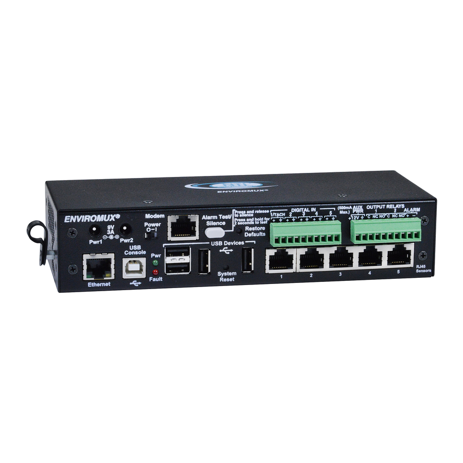
User Interface
Details the LEDs on the ENVIROMUX-5D front panel.
RJ45 Sensor Inputs
Specifications for the RJ45 sensor input connectors on the ENVIROMUX-5D.
Digital Inputs
Specifications for the digital input terminals on the ENVIROMUX-5D.
Output Relays
Specifications for the output relay terminals on the ENVIROMUX-5D.
Alarm Port
Specifications for the alarm port on the ENVIROMUX-5D.
USB Device Ports
Specifications for the USB device ports on the ENVIROMUX-5D.
USB-Serial Port “Console”
Specifications for the USB serial console port on the ENVIROMUX-5D.
ENVIROMUX-2D SPECIFICATIONS
User Interface
Details the LEDs on the ENVIROMUX-2D front panel.
RJ45 Sensor Inputs
Specifications for the RJ45 sensor input connectors on the ENVIROMUX-2D.
Digital Inputs
Specifications for the digital input terminals on the ENVIROMUX-2D.
Output Relays
Specifications for the output relay terminals on the ENVIROMUX-2D.
USB Device Ports
Specifications for the USB device ports on the ENVIROMUX-2D.
USB-Serial Port “Console”
Specifications for the USB serial console port on the ENVIROMUX-2D.
WIRING METHODS
RS485 Sensor Cable
Wiring specifications for RS485 sensor cables using CAT5 connectors.
Contact Sensor Wiring
Wiring details for connecting contact sensors to RJ45 sensor sockets.
TROUBLESHOOTING
WARRANTY INFORMATION
Table of Contents
Save PDF
Print
Rename the bookmark
Delete bookmark?
Delete from my manuals?
Login
Sign In
OR
Sign in with Facebook
Sign in with Google
Upload manual
Upload from disk
Upload from URL
Need help?
Do you have a question about the ENVIROMUX-5D and is the answer not in the manual?
Questions and answers