
Subscribe to Our Youtube Channel
Related Manuals for Simrad PI44 - INSTALLATION REV A


Summary of Contents for Simrad PI44 - INSTALLATION REV A
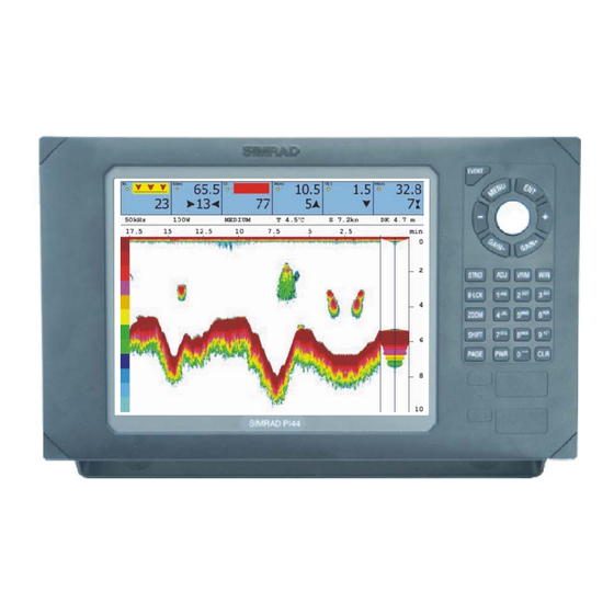
- Page 1 Installation manual Simrad PI44 Catch monitoring system www.simrad.com M A X I M I Z I N G Y O U R P E R F O R M A N C E S E A...
- Page 3 851-165101 / Rev.A Simrad PI44 Catch monitoring system Installation manual NOTICE Operation of the PI44 system assumes that the communication between the Operator Unit and the sensors fully functional. Ensure that communication channels defined on the Operator Unit matches those of the sensors.
- Page 4 The information contained in this document is subject to change without prior notice. Simrad AS shall not be liable for errors contained herein, or for incidental or consequential damages in connection with the furnishing, performance, or use of this document.
- Page 5 Installation manual Sections Introduction This section provides a general introduction to the PI44 installation. Refer to page 1. Echo sounder transducer installation This section provides general guidelines for the installation of the optional echo sounder transducer. Refer to page 18. Purse hydrophone installation This section provides general guidelines for the installation of the PI44 purse seine hydrophone.
-
Page 6: Table Of Contents
Simrad PI44 INTRODUCTION ......... - Page 7 Installation manual Installation drawings ........14 PORTABLE HYDROPHONE .
- Page 8 Simrad PI44 851-165101 / Rev.A...
-
Page 9: Introduction
Introduction 1 INTRODUCTION The purpose of this manual is to provide the information and basic drawings required for installation of the Simrad PI44 catch monitoring system. These instructions must be followed carefully to ensure optimal system performance. As a guide, installation procedures are presented in the order they are to be performed. -
Page 10: System Diagram
Simrad PI44 System diagram (A) = Operator Unit (B) = PI charger (C) = Hydrophone (provides communication with the sensors) (D) = Optional echo sounder transducer. Several types are available. (E) = Sensors mounted on the net. Maximum six sensors may be used simultanously, and several types are available. -
Page 11: Scope Of Supply
38/200 Combi W KSV--208845 50/200 Combi C KSV--202193 50/200 Combi D KSV--203005 Sensors The Simrad PI44 catch monitoring system can operate with six sensors simultanously. Several sensor types are available. Sensor Order number PI Bottom Contact sensor PI3--207642 PI Catch sensor... - Page 12 Simrad PI44 Sensor Order number PI Twin Spread sensor PI3--206896 PI Remote 1 sensor PI3--206870 PI Remote 2 sensor PI3--206871 PI Remote 3 sensor PI3--206872 PI Remote 4 sensor PI3--206885 PI Temperature sensor PI3--207640 Sensor chargers In order to charge the PI44 sensor batteries, the following charger is available.
-
Page 13: Supply Conditions
If any damage to the equipment is discovered, the recipient should notify both the transportation company and Simrad so that Simrad can arrange for replacement or repair of the damaged equipment. Once unpacked, the equipment must be stored in a controlled environment with an atmosphere free of corrosive agents, excessive humidity or temperature extremes. -
Page 14: General Installation Requirements
Simrad PI44 General installation requirements Responsibility and approval The Simrad PI44’s hydrophone and echo sounder installation must be approved on a case-by-case basis with regard to the vessel’s national registry and corresponding maritime authority. The shipowner and shipyard performing the installation are responsible for obtaining installation approval. -
Page 15: Equipment Handling
Unless otherwise stated in the accompanying documentation, electronic, electro-mechanical and mechanical units supplied by Simrad can be transported using all methods approved for delicate equipment; (by road, rail, air or sea). The units are to be transported in accordance with general or specific instructions for the appropriate unit(s), using pallets, transport cases, or carton boxes as appropriate. - Page 16 Simrad PI44 Heavy units may be equipped with lifting lugs for transportation by crane within the workshop or installation area. Before a crane is used, check: • The applicable weight certificate for the crane. • The security of the lifting lugs.
- Page 17 Introduction - If any units are damaged, prepare an inspection report stating the condition of the unit and actions taken. Describe the damage and collect photographic evidence if possible. Re-preserve the equipment. - If the units are not damaged, check the humidity absorbing material.
- Page 18 Describe the damage and collect photographic evidence if possible. Send the inspection report to Simrad as soon as possible. • If the units are not damaged, check the humidity absorbing material. If required, dry or replace the bags, then repack the unit(s) according to the packing instructions.
- Page 19 Introduction • Place the carton on a stable work bench or on the floor with the top of the carton uppermost. • In the absence of other instructions, always open the top of the carton first. The contents will normally have been lowered into the carton from above, so this will usually be the easiest route to follow.
- Page 20 Simrad PI44 Note: Do not break the seal to open a circuit board package before the board is to be used. If the board package is returned to the manufacturers with the seal broken, the contents will be assumed to have been used and the customer will be billed accordingly.
- Page 21 Introduction Once unpacked, the equipment must be kept in a dry, non condensing atmosphere, free from corrosive agents and isolated from sources of vibration. Note: Do not break the seal to open a circuit board package before the board is to be used. If the board package is returned to the manufacturers with the seal broken, the contents will be assumed to have been used and the customer will be billed accordingly.
- Page 22 The mediums to be used will normally be defined in the unit’s maintenance manual. Cables Wipe clean all exposed cables, and check for damage. If a cable shows signs of wear or ageing, contact Simrad for advice. 851-165101 / Rev.A...
- Page 23 Introduction Internal batteries If the unit contains batteries, these may discharge slowly during storage. If the unit is to be stored for an extended period, disconnect or remove all internal batteries. A suitable piece of insulating material can be placed between the battery and the electrical contacts to prevent electrical discharge.
- Page 24 Simrad PI44 ESD precautions Electro-Static Discharge (ESD) is the transfer of an electrostatic charge between two bodies at different electrostatic potentials, caused either by direct contact or induction by an electrostatic field. The passing of a charge through an electronic device can cause localised overheating, and it can also “puncture”...
- Page 25 Introduction Temperature protection If the unit must be protected against extremes of temperature, the carton/crate must be lined on all walls, base and lid with 5 cm thick polyurethane or polystyrene foam. These units will be identified as delicate in the applicable documentation.
-
Page 26: Transducer Installation
• Simrad 38-200 Combi C (dual frequency) • Simrad 38-200 Combi D (dual frequency) • Simrad 38-200 Combi W (dual frequency, wide beam) Other transducers may also be used. Budget transducers designed for leasure crafts are however not recommended for professional fishery applications. -
Page 27: Transducer Location
Transducer installation Transducer location General A single answer to the question where to locate the transducer cannot be given. It depends very much on the vessel’s construction. However, there are some important guide lines. Go deep The upper water layers of the sea contain a myriad of small air bubbles created by the breaking waves. - Page 28 Simrad PI44 Boundary water layer When the vessel forces its way through the sea, the friction between the hull and the water creates a boundary layer. The thickness of the boundary layer depends upon vessel speed and the roughness of the hull. Objects protruding from the hull, and dents in the hull, disturb the flow and increase the thickness of the boundary layer.
- Page 29 Transducer installation Propeller noise The propulsion propeller is the dominant noise source on most fishing vessels, research vessels, merchant vessels and pleasure crafts. The noise is transmitted through the sea water. For this reason, the transducer should be placed far away from the propeller, which means on the fore part of the hull.
- Page 30 Simrad PI44 Summary and general recommendation Some of the above guide lines are conflicting, and each case has to be treated individually in order to find the best compromise. Generally the propeller noise is the dominant factor, and a recommended transducer location is in the fore part of the hull, with maximum distance from the bow equal to one third of the total length of the hull at the water line.
-
Page 31: External Mounting
Transducer installation External mounting This transducer has a streamlined housing, and it is designed for installation outside the hull. This transducer is mainly used on smaller vessels. A location approximately 0.5 m aside from the keel may be adequate for the passage of water between the keel and the transducer. - Page 32 Simrad PI44 Steel hull A fairing (A), made by the shipyard, is placed between the transducer and the hull. It is required in order to adapt for the deadrise angle of the hull, and it will also house a cable service loop (B).
- Page 33 Transducer installation Wood or polyester hull A fairing (A), made by the shipyard, is placed between the transducer and the hull. It is required in order to adapt for the deadrise angle of the hull, and will also house a cable service loop (B).
- Page 34 Simrad PI44 Flat hull If the vessel’s hull is flat you do not need a fairing. The transducer is then be bolted directly to the hull using two bronze or stainless steel bolts (I) and a cable bushing. Note that the...
- Page 35 Transducer installation Longitudinal angle On deplacement hulls, the transducer (A) must be mounted in an angle of 5 to 8 degrees (B) in relation to the keel (C). With a planing hull, this angle must be 0 degrees. (A) = Transducer (B) = 5 to 8°...
-
Page 36: Transducer Blister
Simrad PI44 Transducer blister With a transducer with circular housing, one recommended installation method is by using a blister. The transducer blister must be designed and manufactured by the installation shipyard to fit the vessel’s sixe and hull shape. Mounting and clamping rings... - Page 37 Transducer installation Example: Large transducer The illustration below shows a typical transducer blister designed for a large transducer. Note that due to the physical size of the transducer, a U-shaped support bar (E) is used to support the transducer. (A) = Streamlined blister (F) = Forward (B) = Stiffening rib (G) = Cable service loop...
- Page 38 Simrad PI44 Example: Small transducer The illustration below shows a typical transducer blister designed for a small transducer. The same blister design principles as for a large transducer apply. (A) = Streamlined blister (E) = Air outlet (B) = Mounting ring...
- Page 39 Transducer installation Common guidelines The best performance is obtained with a blister height of 40 cm or more. A streamlined shape and rounded edges reduce the flow noise. A vertical leading edge or front will guide the aerated water to the sides of the blister. The orientation of the blister should follow the water flow.
- Page 40 Simrad PI44 Physical location The blister is placed on one of the sides of the hull, and the distance from the keel is a trade off between a close distance giving a turbulent flow of water in a narrow passage, and a large distance bringing the transducer higher up and also more affected by vessel roll.
-
Page 41: Box Keel
Transducer installation Box keel Vessels with a box keel may use this for transducer installation. The box keel is already the deepest part of the vessel. If the box keel is too narrow to accommodate the transducer, it can be widened, either symmetrically or to one side only. - Page 42 Simrad PI44 Example The figure below illustrates a symmetrical box keel installation. (A) = Box keel (D) = Cable in steel conduit (B) = U-shaped support bar (E) = Cable service loop (C) = Stuffing tube 851-165101 / Rev.A...
-
Page 43: Cable Glands
Note: Simrad strongly recommends that a length of conduit is fitted around transducer cable glands made of steel or bronze and extended over the water-line inside the vessel. This precaution reduces the danger of flooding in the event of gland failure and transducers installed in this manner are also easier to replace. - Page 44 (or a junction box) The gland gland kit includes all of the necessary parts needed to install the unit excluding screws. Simrad recommends that a one inch steel conduit (that the transducer cable will be run through) with an inside threaded diameter of three-quarter inches is welded to the gland’s stuffing tube.
- Page 45 (or a junction box) The gland gland kit includes all of the necessary parts needed to install the unit excluding screws. Simrad recommends that a one inch steel conduit (that the transducer cable will be run through) with an inside threaded diameter of three-quarter inches is attached to the gland’s packing nipple.
- Page 46 Simrad PI44 Cable gland installation for smaller vessels This cable glands made of plastic is designed for those smaller vessels that do not need to be classified. (A) = Packing nut (bronze). Ensure that you do not to damage the transducer cable by...
-
Page 47: Cable In Steel Conduit
Transducer installation Cable in steel conduit It is strongly recommended to lay a steel conduit from the transducer’s cable gland to the echo sounder transceiver, and to pull the transducer cable through this conduit. There are two reasons for this. •... -
Page 48: Handling And Maintenance
An anti-fouling paint may be applied to the transducer face. Because some paint types may be aggressive to the polyurethane in the transducer face, please consult Simrad’s list of approved paints on the next page. Note: Arctic tanks have acoustic windows made of polycarbonate. -
Page 49: Approved Anti-Fouling Paints
Transducer installation Approved anti-fouling paints This is Simrad’s list of approved antifouling paints on polyurethane transducer housing. From Jotun Paints, Sandefjord Norway: • Antifouling Seamate HB 33 • Antifouling Seamate HB 66 • Antifouling Seamate HB 99 • Racing • Non-stop From International Paints: •... -
Page 50: Purse Seine Hydrophone
Simrad PI44 3 PURSE SEINE HYDROPHONE Purpose The purpose of this chapter is to provide general guidelines for the installation of the PI44 hydrophone for purse seining. Note: If your vessel shall be fitted for trawl operations, DO NOT install the hydrophone(s) as explained in this chapter! -
Page 51: Installation Precautions
Purse seine hydrophone installation Installation precautions Caution: The following precautions must be observed. Failure to do so can result in damage to the hydrophone which may render the PI44 catch monitoring system inoperative. Observe the maximum allowable torque warning of 5 Nm when tightening the hydrophone studs. -
Page 52: Considerations
Note: Simrad strongly suggests that this information is read thoroughly, and that the instructions are understood and followed. Proper hydrophone placement is difficult to achieve, but essential for correct system operation. - Page 53 Purse seine hydrophone installation Boundary water layers: (A) = Turbulent flow (B) = Laminar flow (C) = Air bubbles in the water Air bubbles may also be introduced into the boundary layer. If the vessel’s hull has little flare and is relatively narrow, bubbles may escape to the sea surface without incident.
- Page 54 Simrad PI44 Propeller noise A vessel’s main propeller is the dominant source of underwater acoustic noise. When ever possible, hydrophone(s) should be located as far a way as possible from the main propeller and never closer than ten meters. Hydrophone(s) should not be mounted in the direct acoustic path (line-of-sight) of the main propeller unless absolutely necessary.
- Page 55 Purse seine hydrophone installation When not in operation, bow/sternthruster tunnels create turbulence and hence underwater noise when a vessel is under way. Also, as a vessel pitches in heavy weather, thruster tunnels may fill with air or aerated water which can disturb hydrophone reception when released.
-
Page 56: Pre-Installation Check-List
To aid in this evaluation process Simrad recommends that this installation manual be read thoroughly and the following check list completed before deciding on a final installation strategy for the PI44 system. - Page 57 Purse seine hydrophone installation Conduit used to run hydrophone cables in the interior of a vessel’s hull should extend well over its water line. If you install both trawl and purse seine hydrophones, do not confuse the two types. The Trawl hydrophones are marked with order number 314-205250, while the Purse seine hydrophones are marked with order number 314-202275.
-
Page 58: Optimal Location Of Purse Seine Hydrophones
Simrad PI44 Optimal location of purse seine hydrophones The most influential factors effecting hydrophone reception common to most vessels are: • Noise from cavitation generated by the main propeller. • Air bubbles in the water around the hydrophone which impede acoustic signals. -
Page 59: Coverage Area, Orientation And Tilt
Purse seine hydrophone installation Coverage area, orientation and tilt General Once the fore and aft placement of the purse seine hydrophone is decided, it is equally important to carefully consider its horizontal and vertical orientation. Hydrophone orientation can have a large influence on system performance. The hydrophone’s beam sensitivity is concentrated within a 90_ horizontal and -30_ vertical sector. - Page 60 Simrad PI44 Figure 1 Horizontal coverage area The illustration shows a hydrophone installed at an angle of 70 degrees to the vessel’s center line. (A) = The PI44 hydrophone (B) = The horizontal coverage area Vertical coverage area The hydrophone has a vertical beam width of -30_ and should be tilted so that the most important part of the seine is adequately covered.
- Page 61 Purse seine hydrophone installation Tilt angle The tilt angle is a function of net length and depth and may be estimated as follows: α = - [arctan (depth/length π) - 15_+ β] α = tilt angle β = angle of heel (to port) after deploying the purse seine to starboard The following table gives some examples of recommended tilt angles for common size pure seines:...
-
Page 62: Mounting Arrangement
Simrad PI44 Mounting arrangement The PI44 purse hydrophone are delivered ready for installation in either freestanding or keel mounted shoes (which are to be built by the shipyard responsible for the installation). Several alternatives with corresponding detailed drawings have been included in this manual to cover the majority of installation options available. - Page 63 Purse seine hydrophone installation Keel mounted shoes The hydrophone shoe may be keel mounted to avoid creating an appendage to the hull which may foul the purse wire. Keel mounted hydrophone shoe: (A) = Tilt angel (B) = Vertical coverage area (C) = Keel mounted hydrophone with fairing Should this solution be chosen, the...
- Page 64 Simrad PI44 Free standing hydrophone in blister If there is no risk that hull protrusions will be fouled by the purse wire, mounting the hydrophone in a freestanding blister is a viable option. Free standing hydrophone in blister: (A) = Tilt angel...
-
Page 65: Dual Hydrophone Installation
Purse seine hydrophone installation Dual hydrophone installation Large vessels and operations requiring a greater than normal coverage area can install two hydrophones with a vertical and horizontal overlap. Hydrophone selection is made with the help of a switch located in the wheelhouse. To reduce the possibility of interference from air bubbles and underwater noise when reversing propulsion or using thrusters the two hydrophones should be located at least five meters from... - Page 66 Simrad PI44 Vertical coverage areas When the seine is normally located forward of the starboard beam when pursing the following information should be taken into consideration: • The optimal tilt angle for dual hydrophone installations is derived in the same manner as a for single hydrophone installations.
-
Page 67: Hydrophone Protection
Deflection plates Simrad recommends that hydrophones mounted in blisters be protected by rope deflections plates both forward and aft. Such precautions will help protect the hydrophones, especially in the event the vessel passes over a wire, line or net. - Page 68 Hydrophone face This is Simrad’s list of approved antifouling paints for hydrophone faces. From Jotun Paints, Sandefjord Norway: • Antifouling Seamate HB 33, HB 66 and HB 99 •...
- Page 69 Purse seine hydrophone installation Location and marking After installation, the location of hydrophones should be clearly marked on the vessel’s hull (above the water-line) directly over them. This information will help prevent hydrophone damage when dry-docking the vessel. It is very important to amend the docking-plans of larger vessels to also reflect this information so that blocks will not be placed in the vicinity of hydrophones, fins, deflection plates or other associated appendages.
-
Page 70: Hydrophone Cable
Note: Simrad strongly recommends that a length of conduit be fitted around hydrophone cable glands made of steel or bronze and extended over the water-line inside the vessel. This precaution reduces the danger of flooding in the event of gland failure and hydrophones installed in this manner are also easier to replace. - Page 71 Purse seine hydrophone installation Cable gland installation for steel hulls The cable gland kit for steel vessels is included with standard deliveries. The drawing shows a single hydrophone, but normally a typical installation includes two hydrophones with respective cables spliced in a junction box and run to the wheelhouse in a conduit.
- Page 72 Simrad recommends that a one inch conduit (that the hydrophone cable will be run through) with an inside threaded diameter of three-quarter inches be attached to the gland’s packing nipple. This connection must be watertight, and the conduit must extend to over the vessel’s water line and...
- Page 73 Purse seine hydrophone installation Cable gland installation for smaller vessels Cable glands made of plastic for those smaller vessels that do njot need to be classified are optional equipment for standard deliveries. This cable gland kit is not included in the standard delivery, and must be ordered separately.
- Page 74 Cable shielding must be continuous. The shielding is terminated in the cabinet and must not be grounded in the junction boxes. In order to minimize electrical interference, Simrad strongly recommends that the hydrophone cable is installed in a metal conduit between the hydrophone and the PI44 cabinet.
-
Page 75: Installation Drawings
Purse seine hydrophone installation Installation drawings Observe the following drawings. The drawings are also available on electronic format (DWG or PDF), consult your local dealer. → PI44 Purse hydrophone, outline dimensions, page 68 → PI44 Purse hydrophone, cutout, page 69 →... - Page 76 Simrad PI44 PI44 Purse Seine hydrophone - Outline dimensions 851-165101 / Rev.A...
- Page 77 Purse seine hydrophone installation PI44 Purse Seine hydrophone - Cutout 851-165101 / Rev.A...
- Page 78 Simrad PI44 PI44 Purse Seine hydrophone - Keel mounted hydrophone, steel hull - Page 1 851-165101 / Rev.A...
- Page 79 Purse seine hydrophone installation PI44 Purse Seine hydrophone - Keel mounted hydrophone, steel hull - Page 2 851-165101 / Rev.A...
- Page 80 Simrad PI44 PI44 Purse Seine hydrophone - Keel mounted hydrophone, steel hull - Page 3 851-165101 / Rev.A...
- Page 81 Purse seine hydrophone installation PI44 Purse Seine hydrophone - Keel mounted hydrophone, wooden hull - Page 1 851-165101 / Rev.A...
- Page 82 Simrad PI44 PI44 Purse Seine hydrophone - Keel mounted hydrophone, wooden hull - Page 2 851-165101 / Rev.A...
- Page 83 Purse seine hydrophone installation PI44 Purse Seine hydrophone - Keel mounted hydrophone, wooden hull - Page 3 851-165101 / Rev.A...
- Page 84 Simrad PI44 PI44 Purse Seine hydrophone - blister installation on steel hull - Page 1 851-165101 / Rev.A...
- Page 85 Purse seine hydrophone installation PI44 Purse Seine hydrophone - blister installation on steel hull - Page 2 851-165101 / Rev.A...
- Page 86 Simrad PI44 PI44 Purse Seine hydrophone - blister installation on steel hull - Page 3 851-165101 / Rev.A...
-
Page 87: Trawl Hydrophone
Trawl hydrophone installation 4 TRAWL HYDROPHONE Purpose The purpose of this chapter is to provide general guidelines for the installation of the PI44 hydrophone for trawl.. Note: If your vessel shall be fitted for purse seine operations, DO NOT install the hydrophone(s) as explained in this chapter! Order numbers Trawl hydrophone, complete: HYD-205254 Trawl hydrophone, without cable gland: HYD-205826... -
Page 88: Installation Precautions
Simrad PI44 Installation precautions Caution: The following precautions must be observed. Failure to do so can result in damage to the hydrophone which may render the PI44 catch monitoring system inoperative. Observe the maximum allowable torque warning of 5 Nm when tightening the hydrophone studs. -
Page 89: Considerations
Note: Simrad strongly suggests that this information is read thoroughly, and that the instructions are understood and followed. Proper hydrophone placement is difficult to achieve, but essential for correct system operation. - Page 90 Simrad PI44 Boundary water layers: (A) = Turbulent flow (B) = Laminar flow (C) = Air bubbles in the water Air bubbles may also be introduced into the boundary layer. If the vessel’s hull has little flare and is relatively narrow, bubbles may escape to the sea surface without incident.
- Page 91 Trawl hydrophone installation Propeller noise A vessel’s main propeller is the dominant source of underwater acoustic noise. When ever possible, hydrophone(s) should be located as far a way as possible from the main propeller and never closer than ten meters. Hydrophone(s) should not be mounted in the direct acoustic path (line-of-sight) of the main propeller unless absolutely necessary.
- Page 92 Simrad PI44 When not in operation, bow/sternthruster tunnels create turbulence and hence underwater noise when a vessel is under way. Also, as a vessel pitches in heavy weather, thruster tunnels may fill with air or aerated water which can disturb hydrophone reception when released.
- Page 93 Trawl hydrophone installation Drop keel In the event the vessel is equipped with a drop keel, the hydrophones should be mounted aft of it. The choice between installing a one, or two hydrophone system should be based on the same horizontal and vertical coverage requirements for vessels operating under similar conditions with fixed keels.
-
Page 94: Pre-Installation Check-List
To aid in this evaluation process Simrad recommends that this installation manual be read thoroughly and the following check list completed before deciding on a final installation strategy for the PI44 system. - Page 95 Trawl hydrophone installation The hydrophone that is closest to the main propeller should be located on the port side of the vessel and have the greatest tilt. If both hydrophone are located equally distant from the main propeller, but are tilted differently, the starboard hydrophone should be tilted the most because underwater acoustic noise is more prevalent on that side of the vessel.
-
Page 96: Optimal Location Of Trawl Hydrophones
Simrad PI44 Optimal location of trawl hydrophones The most influential factors effecting hydrophone reception common to most vessels are: • Noise from cavitation generated by the main propeller. • Air bubbles in the water around the hydrophone which impede acoustic signals. - Page 97 Trawl hydrophone installation also aid in reducing the effects of turbulence, hydrophones should be installed as deeply as possible (preferably 600 mm, but not less than 400 mm) from the vessel’s outer hull. When ever possible, the distance from the keel to the bottom of the hydrophone blister should not exceed 50 mm which can be adjusted by countersinking the installation.
- Page 98 Simrad PI44 trawling in both deep and shallow water tilt one preferably 15 degrees and the other preferably 30 degrees. The hydrophone closes to the propeller should be tilted the most and care should be taken with regard to underwater acoustical noise.
-
Page 99: Coverage Area, Orientation And Tilt
Trawl hydrophone installation Coverage area, orientation and tilt Once the fore-and-aft placement of the hydrophone is decided, it is equally important to carefully consider its horizontal and vertical orientation. Hydrophone orientation can have a large influence on system performance. Hydrophones must be configured so that they overlap one an other in the horizontal plane. - Page 100 Simrad PI44 Vertical coverage area I Dual hydrophone installation with hydrophones equally distant from the bow, but tilted differently. Typical tilt configuration for operation in both deep and shallow water when the hydrophones have the same distance from bow. The hydrophones may be installed in shoes or blisters.
- Page 101 Trawl hydrophone installation Vertical coverage area II Dual hydrophone installation with hydrophones different distances from the bow, and tilted differently. Typical tilt configuration for operation in both deep and shallow water when hydrophones have different distances from bow. (A) = Port hydrophone tilted 20 to 35 degrees (B) = Starboard hydrophone tilted 10 to 20 degrees The hydrophone closest to the main propeller should be on the port side of the hull and have the greater tilt of the two,...
- Page 102 Simrad PI44 Simrad recommends that hydrophone tilt be preferably 20 degrees for normal trawling. If the vessel plans to operate in deep water the tilt can be increased to approximately 30 to 35 degrees or reduced to 10 degrees if trawling will be performed at or near the surface.
-
Page 103: Mounting Arrangement
Trawl hydrophone installation Mounting arrangement The PI44 trawl hydrophones are delivered ready for installation in either freestanding or keel mounted shoes (which are to be built by the shipyard responsible for the installation). Several alternatives with corresponding detailed drawings have been included in this manual to cover the majority of installation options available. - Page 104 Simrad PI44 Freestanding hydrophones in blisters For trawlers that do not have to take a pursing wire into consideration, hydrophones can be mounted in specially constructed blisters offset from the vessel’s keel (preferably 1200 mm, but no less than 700 mm) to avoid turbulence.
- Page 105 Trawl hydrophone installation The farther away from the hull a hydrophone is mounted the more the effects of turbulence are reduced. Simrad recommends that hydrophones be installed as deeply as possible (preferably 600 mm, but not less than 400 mm) from the vessel’s outer hull.
- Page 106 Simrad PI44 Keel mounted shoes Hydrophones can be keel mounted to avoid creating appendages to the hull that could foul the purse wire. Keel mounted hydrophone shoes, top view. (A) = Keel (B) = Towards the bow (S) = Starboard shoe with hydrophone...
- Page 107 Trawl hydrophone installation Mounting at the aft end of a shoe Hydrophones can be mounted at the after end of a transducer shoe for an echo sounder or other underwater acoustic equipment. The distance between the hydrophone and such equipment must not be less than one meter and the greater the separation, the better.
- Page 108 Simrad PI44 Mounting at the after end of a bulbous bow Trawling hydrophones have been successfully installed at the after end of bulbous bows (for vessels trawling in deep water and require tilt angles from 25 to 35 degrees). Vessels equipped...
-
Page 109: Dual Hydrophone Installation
Simrad recommends the use of two hydrophones to ensure the necessary horizontal and vertical coverage for proper system operation. This also allow the respective coverage areas of the... -
Page 110: Hydrophone Protection
Deflection plates Simrad recommends that hydrophones mounted in blisters be protected by rope deflections plates both forward and aft. Such precautions will help protect the hydrophones, especially in the event the vessel passes over a wire, line or net. - Page 111 Hydrophone face This is Simrad’s list of approved antifouling paints for hydrophone faces. From Jotun Paints, Sandefjord Norway: • Antifouling Seamate HB 33, HB 66 and HB 99 •...
- Page 112 Simrad PI44 Location and marking After installation, the location of hydrophones should be clearly marked on the vessel’s hull (above the water-line) directly over them. This information will help prevent hydrophone damage when dry-docking the vessel. It is very important to amend the...
-
Page 113: Hydrophone Cable
Note: Simrad strongly recommends that a length of conduit be fitted around hydrophone cable glands made of steel or bronze and extended over the water-line inside the vessel. This precaution reduces the danger of flooding in the event of gland failure and hydrophones installed in this manner are also easier to replace. - Page 114 Simrad PI44 Cable gland installation for steel hulls The cable gland kit for steel vessels is included with standard deliveries. The drawing shows a single hydrophone, but normally a typical installation includes two hydrophones with respective cables spliced in a junction box and run to the wheelhouse in a conduit.
- Page 115 Simrad recommends that a one inch conduit (that the hydrophone cable will be run through) with an inside threaded diameter of three-quarter inches be attached to the gland’s packing nipple. This connection must be watertight, and the conduit must extend to over the vessel’s water line and...
- Page 116 Simrad PI44 Cable gland installation for smaller vessels Cable glands made of plastic for those smaller vessels that do njot need to be classified are optional equipment for standard deliveries. This cable gland kit is not included in the standard delivery, and must be ordered separately.
- Page 117 Cable shielding must be continuous. The shielding is terminated in the cabinet and must not be grounded in the junction boxes. In order to minimize electrical interference, Simrad strongly recommends that the hydrophone cable is installed in a metal conduit between the hydrophone and the PI44 cabinet.
-
Page 118: Installation Drawings
Simrad PI44 Installation drawings Observe the following drawings. The drawings are also available on electronic format (DWG or PDF), consult your local dealer. → PI44 Trawl hydrophone, outline dimensions, page 111 → PI44 Trawl hydrophone, cut-out, page 112 → PI44 Trawl hydrophone, mounting flange, page 114 →... - Page 119 Trawl hydrophone installation PI44 Trawl hydrophone - Outline dimensions 851-165101 / Rev.A...
- Page 120 Simrad PI44 PI44 Trawl hydrophone - Cut-out - Page 1 851-165101 / Rev.A...
- Page 121 Trawl hydrophone installation PI44 Trawl hydrophone - Cut-out - Page 2 851-165101 / Rev.A...
- Page 122 Simrad PI44 PI44 Trawl hydrophone - Mounting flange - Page 1 851-165101 / Rev.A...
- Page 123 Trawl hydrophone installation PI44 Trawl hydrophone - Mounting flange - Page 2 851-165101 / Rev.A...
- Page 124 Simrad PI44 PI44 Trawl hydrophone in blister - Arrangement drawing - Page 1 851-165101 / Rev.A...
- Page 125 Trawl hydrophone installation PI44 Trawl hydrophone in blister - Arrangement drawing - Page 2 851-165101 / Rev.A...
- Page 126 Simrad PI44 PI44 Trawl hydrophone in keel mounted shoes - Arrangement drawing - Page 1 851-165101 / Rev.A...
- Page 127 Trawl hydrophone installation PI44 Trawl hydrophone in keel mounted shoes - Arrangement drawing - Page 2 851-165101 / Rev.A...
-
Page 128: Portable Hydrophone
Simrad PI44 5 PORTABLE HYDROPHONE Purpose The purpose of this chapter is to provide general guidelines for the installation of the PI44 portable hydrophone. The PI44 portable hydrophone has been developed as a temporary measure until a fixed hydrophone can be installed at the vessel’s next dry docking. -
Page 129: General Guidelines
Portable hydrophone General guidelines The following must be taken into consideration when using portable hydrophones: • Sharp edges that could damage the hydrophone cable insulation must be avoided. • Do step on cable lying on deck. • Do not place any objects (light or heavy) on top of cable lying on the deck. -
Page 130: Deployment Over The Side
Simrad PI44 Deployment over the side Unlike permanently mounted hydrophones, the portable hydrophone has an omni-directional beam. It can therefore be lowered below the level of high underwater noise and air bubbles generated by the main propeller and bow/sternthrusters which can block reception of hull mounted units. -
Page 131: Paravane Arrangement
The hydrophone weighs approximately 700 grams (in salt water) and can be mounted on a towed paravane. Simrad can supply a simple solution for this. This solution is suitable for smaller vessels, and it is made up of a little paravane and a weight. - Page 132 Simrad PI44 Paravane arrangement, parts The relevant part numbers in the arrangement kit are provided in brackets. (1) Towed hydrophone, portable type. Note that the hydrophone is NOT a part of the paravane kit, it must be ordered seperately. Order number is 314-203863.
- Page 133 (314-203863). (B) Paravane, included with KIT-207284. (C) Trolling weight, included with KIT-207284. (D) Snatch block, not available from Simrad. (E) Boom, not available from Simrad. (F) Hydrophone cable, included with the portable hydrophone. (G) Bight, in hydrophone cable secured with an elastic strop to...
-
Page 134: Portable Hydrophone Storage
Simrad PI44 Portable hydrophone storage The portable hydrophone and cable must not be left on deck unattended when not in use. When stored, observe the following precautions. • Prior to storage, clean the hydrophone with fresh water. • Take care so that the cable does not chafe due to the motion of the vessel. -
Page 135: Operator Unit
Operator unit installation 6 OPERATOR UNIT Purpose The purpose of this chapter is to provide general guidelines for the installation of the PI44 Operator Unit Topics → Installation choices, page 128 → Outline dimensions drawing, page 130 → Panel cut-out drawing, page 131 →... -
Page 136: Installation Choices
Simrad PI44 Installation choices The PI44 Operator Unit can be installed as follows: • Table • Bulkhead • Deckhead • Panel/console Table Secure the mounting bracket with four bolts to the table. Loosen the large thumbscrews (A) on each side of the cabinet, and tilt the cabinet backwards to the preferred angle. - Page 137 Operator unit installation Bulkhead Secure the mounting bracket to the upper or lower mounting holes. If you use the lower position you will be able to tilt the cabinet forward. If you wish to tilt the cabinet upwards, you need to use the upper mounting position.
- Page 138 Simrad PI44 PI44 Outline dimensions 851-165101 / Rev.A...
- Page 139 Operator unit installation PI44 Panel cut-out 851-165101 / Rev.A...
- Page 140 Simrad PI44 PI44 Footprint 851-165101 / Rev.A...
-
Page 141: Sensors
Sensors 7 SENSORS The Simrad PI44 catch monitoring system can use a large range of sensors. These sensors are however not installed like the other items described in this manual, but fastened on the nets. Topics → Introduction to the sensors, page 134 →... -
Page 142: Introducing The Sensors
PI Charger. Bottom Contact: Best at the bottom! With patented technology and awardwinning design, Simrad provides you full control of the actions that take place at the bottom. Mounted on a bottom trawl, pelagic trawl or purse... - Page 143 Sensors • Pelagic trawl: On a pelagic trawl, this sensor proves very useful when the trawl moves downwards. It will let you know immediately if the footrope touches bottom. • Purse seine: When you work with a purse seine, you need to know when the seine reaches the bottom.
- Page 144 Simrad PI44 Depth: How deep can you go? When the sonar and echo sounder tell you how deep the school goes, it is good to know that you can place your fishing gear at the same depth. And even better, you can monitor and hold the desired depth.
- Page 145 Sensors Rip: Check for damages! The Rip sensor is identical to the Catch sensor, and can thus be regarded as a application for the Catch sensor. Place the sensor on the trawl belly behind the footrope, and use it to detect if the trawl is torn or in any other ways damaged by rocks or other roughness on the bottom.
- Page 146 Simrad PI44 The water temperature is an important parameter. Fish and bait are temperature sensitive, and they are normally found within specific temperature zones for feeding and spawning. However, the temperature layers in the water are changing constantly, and for this reason the temperature must be monitored constantly.
-
Page 147: Sensor Configuration
Sensors Sensor configuration Communication channels and update rates All sensors are provided from the factory with pre-defined communication channels and update rates. Sensor Com.channel Update rate PI Bottom Contact Normal PI Catch Normal PI Depth (300 m) Fast PI Depth (600 m) Fast PI Depth (1000 m) Fast... - Page 148 Simrad PI44 To change the sensor setup, you can call your local Simrad dealer, or you can do it yourself if you have the proper equipment, training and the PI Configurator software. PI Configurator The PI Configurator application is provided to enable local sensor configuration.
- Page 149 Sensors The two groups must be configured as follows: Configuration Spread sensor Remote sensors PI Twin Spread 1 PI Twin Spread (*) Remote 1 Remote 3 PI Twin Spread 2 PI Twin Spread (*) Remote 2 Remote 4 (*) = The same PI Twin Spread sensor is used for both configurations. By default, it is programmed for PI Twin Spread 1.
-
Page 150: Cable Layout
/or classification society. If no such guide-lines exist, Simrad AS recommends that Det Norske Veritas (DNV) Report No. 80-P008 «Guidelines for Installation and Proposal for Test of Equipment» be used as a guide. -
Page 151: System Cabling
• Corresponding terminations System and shipyard cables Cables fall into two categories: • System cables supplied by Simrad with the standard PI44 system delivery. • Shipyard cables provided by the shipyard performing the installation, or the shipowner. Cables to be provided by the installation shipyard are specified accordingly. -
Page 152: Cable Plan
Simrad PI44 Cable plan The PI44 cable plan is shown on the next page. (A) = Operator Unit (B) = Junction box and/or hydrophone selector switch. One or both can be used, and more than one junction box may also be required on large vessels. - Page 153 Cable layout 851-165101 / Rev.A...
-
Page 154: Cable Specifications
Simrad PI44 Cable specifications The list below specifies each cable used by the PI44 catch monitoring system. References are made to the detailed cable drawings. C1 - DC power supply The PI44 Operator Unit operates on +10 to +32 Vdc. This voltage must be provided by an external power supply. - Page 155 3 meters from the plug. In order to splice the cable you will need a metal junction box. A suitable box may be ordered from Simrad, or you can manufacture or purchase one locally. →...
- Page 156 Simrad PI44 DC Power cable The power connection is made with a cable provided with the cabinet. Use black and red cables only. The blue and white cables may be cut off. Cable specifications Conductors 4 x 0.5 mm2 Screen...
- Page 157 Cable layout NMEA1 and NMEA2 The serial line connections are made using two 9-pin plugs. NMEA1 is female, while NMEA2 is male. Two cables are supplied with the PI44, each with a connector fitted to one end of the cable. The other end of each cable is open, and allows you to connect to external devices through junction boxes or other means of connection.
- Page 158 Simrad PI44 Alarm The Alarm output allows you to take advantage of the built-in relay contacts. Maximum throughput on the relay contacts is 24 Vdc and 0.5 A. Cable specifications Conductors 4 x 0.25 mm2 Screen Overall braided Voltage Max.diameter 8 mm 851-165101 / Rev.A...
- Page 159 Cable layout Cabinet ground A firm ground connection is required. Cable specifications Conductors 1 x 3 mm2 Screen Not applicable Voltage Max.diameter Not applicable 851-165101 / Rev.A...
- Page 160 Simrad PI44 Hydrophone cable The hydrophone is connected to the ANT socket on the rear side of the PI44 Operator Unit. Cable specifications Conductors 6 x 0.5 mm2 + GND Screen Overall braided Voltage Max.diameter 8 mm 851-165101 / Rev.A...
- Page 161 Cable layout Junction box The hydrophone cable will need to be spliced. DO NOT splice with solder and electrical tape, or by using a commercial terminal block for home lightning! You must use a metal box, and the box must be grounded. The cable shielding must however NOT be grounded in the junction box.
- Page 162 Simrad PI44 Echo sounder transducer ECHO1 The ECHO1 socket is used to connect the PI44 Operator Unit to a single frequency echo sounder transducer, as well as external speed log and temperature sensors. Cable specifications Conductors 6 x 0.5 mm2 + GND...
- Page 163 Cable layout Echo sounder transducer ECHO2 The ECHO2 socket is used to connect the PI44 Operator Unit to a dual frequency echo sounder transducer and an external temperature sensor. Cable specifications Conductors 6 x 0.5 mm2 + GND Screen Overall braided Voltage Max.diameter 8 mm...
- Page 164 Simrad PI44 Simrad 38-200 Combi C Observe the diagram below to connect the 38-200 Combi C dual frequency transducer. 851-165101 / Rev.A...
- Page 165 Cable layout Simrad 50-200 Combi C Observe the diagram below to connect the 50-200 Combi C dual frequency transducer. 851-165101 / Rev.A...
- Page 166 Simrad PI44 Simrad 38-200 Combi D Observe the diagram below to connect the 38-200 Combi D dual frequency transducer. 851-165101 / Rev.A...
- Page 167 Cable layout Simrad 50-200 Combi D Observe the diagram below to connect the 50-200 Combi D dual frequency transducer. 851-165101 / Rev.A...
- Page 168 Simrad PI44 Simrad 38-200 Combi W Observe the diagram below to connect the 38-200 Combi W dual frequency transducer. Note that the PI44 will automatically reduce the power output to the 38-200 Combi W transducer in order to compensate for the hogh power efficiency of this transducer.
- Page 169 Cable layout Other transducers Observe the table below to connect other echo sounder transducers. TRANSDUCER ECHO 1 ECHO 2 PINS Airmar 50&200 50: Depth 1 Pins 1 and 2 200: Depth 2 Pins 3 and 5 Airmar 50 (/200) 50: Depth 1 Pins 3 and 5 Airmar 200 (/50) 200: Depth 1...
-
Page 170: Basic Cabling Requirements
Simrad PI44 Basic cabling requirements Cable trays All permanently installed cables associated with the system must be supported and protected along their entire lengths using conduits and/or cable trays. The only exception to this rule is over the final short distance (max. 0.5 metre) as the cables run into the cabinets/units to which they are connected. - Page 171 Cable layout Radio Frequency interference All cables that are to be permanently installed within 9 m (30 ft) of any source of Radio Frequency (RF) interference such as a transmitter aerial system or radio transmitters, must, unless shielded by a metal deck or bulkhead, be adequately screened by sheathing, braiding or other suitable material.
- Page 172 Simrad PI44 Electrical continuity must be ensured along the entire length of all cable coverings, particularly at joints and splices. In no case should the shielding of cables be used as the only means of grounding cables or units. Metallic casings, pipes and conduits must be grounded, and when fitted with joints these must be mechanically and electrically grounded locally.
-
Page 173: Interface Setup
Setup 9 INTERFACE SETUP This chapter describes the setup procedures for the PI44 interfaces. Topics → Hydrophones, page 166 → Echo sounder transducers, page 167 → Positioning and navigation data, page 170 → Water speed, depth and temperature data, page 173 →... -
Page 174: Hydrophones
Simrad PI44 Hydrophones The PI44 will only interface with one hydrophone, but by means of external switches you may use more than one. Once the hydrohpne is connected to the PI44 Operator Unit, there are no further procedures. → Cable details (W813), page 152... -
Page 175: Echo Sounder Transducers
• Simrad 38-200 Combi C (dual frequency) • Simrad 38-200 Combi D (dual frequency) • Simrad 38-200 Combi W (dual frequency, wide beam) Other transducers may also be used. Budget transducers designed for leasure crafts are however not recommended for professional fishery applications. - Page 176 Simrad 38/200 Combi D Connect the transducer as described in the wiring diagram. → Simrad 38/200 Combi D (W814E), page 158 In the Echosunder setup dialogue, use the circular selector pad to move the cursor (inverse video) to the Transducer 1 / Type location.
- Page 177 Simrad 38/200 Combi W Connect the transducer as described in the wiring diagram. → Simrad 38/200 Combi W (W814G), page 160 In the Echosunder setup dialogue, use the circular selector pad to move the cursor (inverse video) to the Transducer 1 / Type location.
-
Page 178: Positioning And Navigation Data
Simrad PI44 Positioning and navigation data The PI44 will interface with external devices using NMEA connectors 1 and 2. → Cable details (W201B), page 149 Once the physical connections have been completed, you can use these procedures to ensure that all interfaces to external devices work properly. - Page 179 Setup Positioning system You can connect the PI44 to a positioning system by means of NMEA1 or NMEA2. In order to set up the PI44 to receive the information, observe the following procedure. A typical setup page is shown. For more detailed information about the parameters, refer to the operator manual.
- Page 180 Simrad PI44 Navigation system You can connect the PI44 to a navigation system by means of NMEA1 or NMEA2. In order to set up the PI44 to receive the information, observe the following procedure. A typical setup page is shown. For more detailed information about the parameters, refer to the operator manual.
-
Page 181: Water Depth, Speed And Temperature
Setup Water depth, speed and temperature The PI44 will interface with sensors for water depth, speed and temperature. Cable details: → Depth sensor (transducer) on ECHO1 (W814A), page 154 → Depth sensor (transducer) on ECHO2 (W814B), page 155 → Speed log on ECHO1 (W814A), page 154 →... - Page 182 Simrad PI44 Depth sensor The echo sounder transducer is the most likely depth sensor to be used, but you can also connect to external depth sensors using the NMEA interface. A typical setup page is shown. For more detailed information about the parameters, refer to the operator manual.
- Page 183 Setup Speed sensor The speed sensor may be a separate unit, or it may be integrated with the echo sounder transducer. You can also connect to external water speed sensors using the NMEA interface. A typical setup page is shown. For more detailed information about the parameters, refer to the operator manual.
- Page 184 Simrad PI44 Temperature sensor The temperature sensor may be a separate unit, or it may be integrated with the echo sounder transducer. You can also connect to external water speed sensors using the NMEA interface. A typical setup page is shown. For...
-
Page 185: Data Output On Nmea Format
Setup Data output on NMEA format You can connect the PI44 to external devices and transmit data to them by means of the NMEA1 and/or NMEA2 ports. In order to set up the PI44 to transmit the information, observe the following procedure. -
Page 186: Nmea Interface Verification
Simrad PI44 NMEA Interface verification You can verify the NMEA data traffic in and out of the PI44 by opening the NMEA0183 input or NMEA0183 output pages. These pages present the received and transmitted datagrams in real time. During normal operation the information on the pages is hard to read, due to the fact that the ongoing communication provides new data continuously. -
Page 187: Installing Sensor Adaptors
Installation of sensor adapters 10 INSTALLING SENSOR ADAPTORS Introduction The PI Spread and PI Remote sensor adaptors must be properly installed, and their protective cages fabricated correctly for the system to operate as designed. Misaligned sensors or cages that interfere with the sensors’ communication signals will negatively effect system performance. -
Page 188: Installation Keypoints
Simrad PI44 Installation keypoints The PI Spread sensor must be mounted on the port door. The PI Remote sensor must be mounted on the starboard door. The installation of the adapters must ensure that there is an unobstructed line of sight between the sensor “eyes” for the transverse communication link. - Page 189 Installation of sensor adapters The PI Spread and PI Remote sensors: (A) = Negative charging and fastening lug (B) = Positive charging and fastening (C) = Communication link to vessel’s hydrophone. Free line of sight must be provided. (D) = Location of sensor lamp (rear side on PI Spread) (E) = Water switch sensor, must have free access to the water once the door...
- Page 190 Simrad PI44 Location of sensor adapters: (A) = Starboard door (B) = Port door (C) = PI Remote sensor adapter (499-207615) (D) = PI Spread sensor adapter (499-207613) (E) = A protection cage is highly recommended for both adapters. It can be manufactured from ø20...
-
Page 191: Before Work Begins
Installation of sensor adapters Before work begins Proper preparation involves becoming familiar with all related documentation including: • Drawings 830-208247 and 830-208246 in full size (1:1) printout. With the proceeding information in mind: • Determine the optimal sensor placement and orientation with regard to the intended operation of the vessel. - Page 192 Simrad PI44 STEP 1: Cut openings in the doors for the sensor adapters Using drawing 830-208247 as a guide, and mark off the areas to be cut out. Note that you need to have the drawing available in size 1:1.
- Page 193 Installation of sensor adapters 2) Orient the sensor adapters Position the sensor adapters (port and starboard respectively) with the bottom portion just protruding through the back side of the door. Carefully check that the adapters’ angle and orientation are as close to those described in the drawings.
- Page 194 Simrad PI44 STEP 3: Mark the desired position of the sensor adapters With the senor adapter held firmly in the correct position, trace a line around it using the inside surface of the door as a reference point. Remove the sensor adapter. Using a centre punch and hammer, score the the adapter so that this reference line will not be lost when the primer is removed.
- Page 195 Installation of sensor adapters STEP 4: Dismantle the sensor adapters Remove the sensor adapters’ rubber inserts (two) before performing any hot work. Locking devices and internal plastic spacers may remain attached. Note: Over heating of either the sensor adapters or doors must be avoided though out the installation procedure.
- Page 196 Simrad PI44 STEP 5: Weld the sensor adapters to the doors Tack weld sensor adapters in position using the reference line created in step 3 as a guide. Check that both angle and orientation are in agreement with the drawings.
- Page 197 Installation of sensor adapters STEP 6: Measure the dimensions of the protective cage legs Using a yardstick bent at a ninety degree angle, measure the length of standard 20 mm diameter bar stock necessary for the apex of the protective cage to rise approximately 10 to 20 mm over the sensor adapters.
- Page 198 Simrad PI44 STEP 7: Attaching the doubling plates Place the appropriately sized doubling plates on the locations marked in step 6. Temporarily holding the protective cage leg in place, check that the release mechanism operates freely. Note: There must always be enough space between a protective cage and its respective sensor adapter so that in the event it becomes bent, the sensor may still be removed.
- Page 199 Installation of sensor adapters STEP 8: Attach the outboard protective cage legs Tack weld the protective cage legs to the doubling plates. Check the alignment in relationship to the sensor adapter and its release mechanism, adjust as necessary. Weld the protective cage legs permanently in place. 851-165101 / Rev.A...
- Page 200 Simrad PI44 STEP 9: Attach the outboard protective cage stiffener Using a yardstick, and measure the length of standard 20 mm diameter bar stock necessary to span from the apex of the protective cage to the door. Cut and weld the stiffener in place.
- Page 201 Installation of sensor adapters STEP 10: Fabricate and attach the inboard protective cage legs and stiffeners Proceed in the same manner as described in steps 6 through 9. The protective cage is now ready for priming and painting. 851-165101 / Rev.A...
-
Page 202: Software Updates
Note: Even though the software update procedures are uncomplicated, Simrad cannot be held responsible for errors or malfunctions that may occur after a software update, if the update has not been performed according to the procedures, or as a result of technical problems during the upload process. -
Page 203: Dsp Software Upgrade
Software updates DSP Software upgrade Purpose The DSP software is used by the digital signal processor inside the PI44 Operator Unit. This processor controls the interpretation of the coded signals from the sensors. Changing the DSP software will not change any of the menus or presentations on your PI44. - Page 204 The DSP software program file is provided on the following format: 281036xx DSP Vyzz.hex • 281036 is the last part of the order number, and Simrad’s internal identification number for this software. • xx is an internal version code. • DSP identifies the software.
- Page 205 Software updates When the upload process has been started, do not switch off power on the PI44 or the computer, and do not unplug the upload cable. Allow the process to finish. When the software has been uploaded, a message will inform you. Switch off the PI44.
- Page 206 If you loose power on the PI44 cabinet during this critical internal transfer process, you can not restart the upload. You must then contact your Simrad dealer to have the PI44 cabinet shipped for reprogramming. 851-165101 / Rev.A...
-
Page 207: Mmi Software Upgrade
The MMI software upgrade file is provided on the following format: 281037xx MMI Vyzz.exe • 281037 is the last part of the order number, and Simrad’s internal identification number for this software. • xx is an internal version code. • MMI identifies the software. - Page 208 Simrad PI44 Procedure In order to upgrade the MMI software, observe the following procedure. Switch off the PI44. Connect the upload cable between a serial line connector on the computer and the NMEA2 connector on the rear side of the PI44 Operator Unit.
- Page 209 Software updates Switch on the PI44 Operator Unit. Verify that the new software version is shown in the Status display. Messages The MMI upload program will keep you posted on the process by means of messages. Safety measures The following safety measures have been implemented to minimize the risk of errors during the upload process.
-
Page 210: Pi Dsp Upload
Simrad PI44 PI DSP Upload Purpose The PI DSP Upload application is used to upload DSP (Digital Signal Processor) software to the PI44 Operator Unit. The application runs on a standard computer with operating systems Microsoft® Windows 2000® or Windows XP®. - Page 211 Notes...
- Page 212 E 2005 Simrad AS ISBN 82-8066-048-8...
Need help?
Do you have a question about the PI44 - INSTALLATION REV A and is the answer not in the manual?
Questions and answers