
Subscribe to Our Youtube Channel
Related Manuals for Simrad FS 70


Summary of Contents for Simrad FS 70
- Page 1 FS 70 Trawl Sonar System Operator Manual SIMRAD Kongsberg Mesotech Ltd. Port Coquitlam, BC - Canada...
- Page 3 974-24007001/5.0 FS70 Trawl Sonar System Operator manual 974-24007001/5.0...
- Page 4 FS70 Trawl Sonar System Document revisions Date Written by Checked by Approved by Version January 04, 2011 LF/BC February 24, 2016 About this document The information contained in this document is subject to change without prior notice. Kongsberg Mesotech Ltd. shall not be liable for errors contained herein, or for incidental or consequential damages in connection with the furnishing, performance, or use of this document.
-
Page 5: Table Of Contents
2.5.3 RX Gain Response and Type................8 2.5.4 Pulse Length Control ..................8 2.5.5 Peak Detection ....................9 FS 70 SYSTEM OPERATION ................10 Introduction ....................... 10 3.1.1 Processor Requirements ................. 11 3.1.2 Installing DATSS ................... 11 Quick Reference ....................11... - Page 6 FS70 Trawl Sonar System 3.2.1 Starting DATSS: ..................... 11 3.2.2 Sonar Operation: ..................... 14 3.2.2.1 Selecting the Scan Mode: ................ 14 3.2.2.2 Selecting the Bandwidth: ................ 14 3.2.2.3 Changing the Gain:.................. 15 3.2.2.4 Changing the Scan Speed: ............... 15 3.2.2.5 Changing the Gain Type: ................
- Page 7 3.2.7.2 Operating Control Panel Tab..............42 3.2.7.3 Display Control Panel Tab ..............43 3.2.7.4 Setup Control Panel Tab ................. 43 3.2.7.5 Users Settings Control Panel Tab............44 3.2.7.6 Sensors Control Panel Tab ..............44 3.2.7.7 PI 40 kHz Channel Sensors Setup ............46 3.2.7.8 PI 40 kHz Sensors Receiver Setup ............
- Page 8 FS70 Trawl Sonar System 3.2.14 File Types ....................... 60 3.2.15 Activating the Sonar ..................61 FS 70 INSTALLATION INSTRUCTIONS ............62 Installation procedure ..................62 Surface Unit Installation ................... 62 4.2.1 Mounting of Units ..................62 4.2.2 Ship Power Requirement ................63 4.2.3...
- Page 9 TROUBLESHOOTING AND MAINTENANCE ..........74 Introduction ....................... 74 System overview ....................74 Handling & maintenance .................. 74 5.3.1 Wheelhouse Electronics ................. 75 5.3.2 Trawl Unit ...................... 75 5.3.2.1 Handling Tips ..................75 5.3.2.2 Maintenance Schedule................75 5.3.2.3 Connector Maintenance................76 5.3.2.4 Excessive Impacts ...................
- Page 10 FS70 Trawl Sonar System 5.4.12 Diagnostic and Message Files Transfer Procedure ........85 5.4.13 Diagnosing Problems ..................86 5.4.14 Troubleshooting Problems ................87 5.4.15 Power up Sequence of Events ................ 87 5.4.16 Host FS70 Software Start-up Sequence of Events ......... 88 What happens when you click “RUN”...
-
Page 11: System Familiarization
System Familiarization Overview The SIMRAD FS 70 Series is a third wire trawl monitoring system for pelagic and bottom fishing trawlers. The system provides real time information from the trawl sonar head and the associated sensors to the bridge, thus maximizing fishing efficiency and reducing sea time. -
Page 12: Equipment List
FS70 Trawl Sonar System Equipment List A typical FS70 Trawl Monitoring System consists of: FS 70 Deployment Housing FS 70, Vertical Sonar Head 120kHz, or 330kHz, 200kHz Sounder Transducer 40kHz or 70kHz Catch Sensors FS PWR/TTM Interface Unit ... -
Page 13: Display Monitor
Net Geometry Display Monitor The display monitor for the FS 70 can be a LCD monitor but any commercially available monitor may be used. This is in order to have the full benefit of high resolution provided by the video Multi-Display adapter available with the FS Processors. -
Page 14: Processor Unit
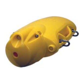
TTM. Deployment Housing Unit The trawl deployment housing unit is made from polyurethane and designed for the harshest of environments yet it is easy to handle. The FS 70 trawl unit sits within the 974-24007001/5.0... -
Page 15: Jointing Tool
The catch sensors are equipped with rechargeable batteries. 1.10 PI Sensors Option The FS 70 provides full integration with the PI System sensors. Door Spread, Net Geometry, Bottom Contact, Rip Sensor and Cod End Depth Sensors available from Simrad AS, Horten Norway. -
Page 16: 1.12 Trawl Cable, Winch And Block
FS70 Trawl Sonar System interfaced to echo sounders or other onboard equipment. The head rope depth information appears on the sounder showing the location of the trawl in relation to the fish or bottom returns. 1.12 Trawl Cable, Winch and Block The trawl cable and the associated equipment are supplied by the vessel. -
Page 17: Determining Target Position
In simple words, the TVG function controls the gain of the receiver so that a school with a given size and density is presented with approximately the same strength on the display, inside the regulated TVG range. Key Features Setting The following paragraphs describe some of the key features of the FS 70 System. 974-24007001/5.0... -
Page 18: Automatic Gain Control (Agc)
2.5.4 Pulse Length Control The FS 70 Trawl Sonar Heads are capable of changing the acoustic pulse length that is transmitted. The surface processing unit sets the pulse length based on the operating range of the sonar head. It is generally better to use a longer pulse as the operating range increases. -
Page 19: Peak Detection
Theory of Operation Maximize Range - The pulse length calculation can be optimized to increase the detection range of the sonar head. Generally, the longer the pulse length, the more energy is transmitted into the water which could then travel a longer distance and get reflected from the targets that are further away from the sonar head. -
Page 20: Fs 70 System Operation
FS70 Trawl Sonar System FS 70 System Operation Introduction The typical screen display for DATSS Sonar Processor consists of a tabbed Control Panel that allows changing the settings and operating parameters of the DATSS System, resizable display areas for the Sonar Head, Sounder and Message Log, a floating dockable Sensor Panel to monitor the sensors status, toolbars for quick access to various functionalities and a status bar to monitor the system status. -
Page 21: Processor Requirements
FS 70 System Operation 3.1.1 Processor Requirements Minimum: 1 GHz 32-bit x86 processor 512 MB RAM 300 MB of free hard drive space One COM port or USB port One Ethernet port One CD ROM or DVD ROM drive ... - Page 22 FS70 Trawl Sonar System The System Configuration page will appear showing available COM ports, KML USB devices and Ethernet devices. 974-24007001/5.0...
- Page 23 FS 70 System Operation To connect a head, click Detect Heads button. A progress bar will be shown as the system establishes communication with the sonar heads. The Part Number and Serial Number of the sonar head will be shown.
-
Page 24: Sonar Operation
FS70 Trawl Sonar System 3.2.2 Sonar Operation: 3.2.2.1 Selecting the Scan Mode: DATSS supports the following scan modes: Polar: used to allow the sonar scan for up to 360 degree. Sector: used to allow the sonar scan in a sector less than 180 degree. ... -
Page 25: Changing The Gain
FS 70 System Operation 3.2.2.3 Changing the Gain: Increase the Gain to get higher intensity image. Decrease the Gain to get lower intensity image. To change the Gain: Click Gain button from the Operation tab. 3.2.2.4 Changing the Scan Speed:... -
Page 26: Changing The Gain Type
FS70 Trawl Sonar System 3.2.2.5 Changing the Gain Type: Gain Type is used to enable elementary image processing for reverberation control (RCG), automatic gain control (AGC) or a combination of the two. AGC (Automatic Gain Control): provide automatic scaling to each sample in order to maintain proper dynamic range based on all sample values. -
Page 27: Changing The Resolution
FS 70 System Operation Gain Response is the severity of the Gain Type affects the sonar image. To change the Gain response: Click Gain R button on the Operation tab. 3.2.2.6 Changing the Resolution: Select low resolution for faster scan rate. -
Page 28: Sonar Operation
FS70 Trawl Sonar System 3.2.3 Sonar Operation Pages: To access sonar operation pages, right click on the sonar image display; select Control Head from the context menu. NOTE: Depending on the version of the DATSS software the operation pages will use either the “Head Settings”... - Page 29 FS 70 System Operation The Scan Mode box allows you to select Polar, Sector, Net Opening, Sounder, Smooth Sounder, or Lock mode. Use the Scan Speed box to select the scanning speed for the head. The Pause Head button will make the head stop scanning and/or pinging.
-
Page 30: The Transmit Page
FS70 Trawl Sonar System 3.2.3.2 The transmit page: The Transmit Page is used to control transmission from the head. The Uplink control is used to set the baud rate at which data is sent from the head to the surface. You will normally want to set this control to as high a rate as your system will support without generating too many errors. - Page 31 FS 70 System Operation Transmitter: The transmitter controls are usually used for receiver test. The Power Control is used to control the current transmit power output. The Hi Acquisition control is used to change the number of samples collected from the sonar head to twice its normal value.
-
Page 32: The Tvg Page
FS70 Trawl Sonar System If the sonar head has an auxiliary sounder, the sounder transmit page has a special control, Transmit Ratio. This is used to control the transmit ratio between the primary transducer and the auxiliary transducer. For example, at transmit ration 1:4, the auxiliary transducer will transmit once every 4 primary transducer transmit. - Page 33 FS 70 System Operation Gain Limit Select Default to use the default upper limit on TVG gain. Select High to set the upper limit on TVG gain higher than default. Select Low to set the upper limit on TVG gain lower than default.
-
Page 34: The Sensor Page
FS70 Trawl Sonar System 3.2.3.4 The Sensor page: The sensor page is used to adjust trawl sensors display information. Graph Time: sets the sensor reading display time. Depth Offset: when depth sensor reading is not accurate, use this offset to compensate the depth reading. -
Page 35: Using The Reference Cursors
FS 70 System Operation 3.2.4.1 Using the reference cursors: The Reference Cursors are two cross-hair type markers that can be placed on the sonar image to mark a point of interest. User can use the reference cursors to measure the range and bearing from the origin. -
Page 36: Using The Tools
FS70 Trawl Sonar System 3.2.4.2 Using the Tools: Tools can be selected from the Display tab. The Tools include the following: Pencil: Used for annotation. Drag from any point on the screen to label that point with a text box overlay. To enter new text or change the existing text, simply double click on the text box. - Page 37 FS 70 System Operation The FS Sensors Gauge Window: The FS Sensors Gauge Window shows the depth and temperature sensor data from the trawl sensor pack. Right-click on the sonar image view and select FS Sensors to display The FS Sensors Gauge Window.
-
Page 38: Nmea Input And Output
FS70 Trawl Sonar System 2. In the "Gauge Windows" dialog box, click "New" button. 3. Enter a name for the new gauge window then click "OK". 4. To add parameters into the gauge window, select from the "Unused Parameters" list then press the "Add"... - Page 39 FS 70 System Operation 1. From the Sensors Configuration page, select a COM port, 2. Select one or more of the NMEA standard in the "Standard" list, and click "Connect". 3. If you have "User Defined" sensors (see section Creating user defined sensors), select one or more from the "User Defined"...
-
Page 40: Creating User Defined Sensors
FS70 Trawl Sonar System To remove a sensor from a COM port: 1. Select the sensor to be removed 2. Click the Disconnect button Select "Adjust System Time" to allow the system clock to be synchronized to the time stamp from the NMEA sensor data. 3.2.5.2 Creating user defined sensors In the User Defined Sensors page, click the Create button to make a new user defined... - Page 41 FS 70 System Operation F --- Search for the next Field Delimiter I --- Ignore a character N --- Print as ASCII to the next Field Delimiter D --- Insert a Decimal point S --- Insert a Space Example Suppose you had a device which provided distance travelled through the water using the NMEA defined VLW sentence: $--VLW,x.x,N,x.x,N*hh<CR><LF>...
-
Page 42: Setting The Com Port For Sensors
FS70 Trawl Sonar System 3.2.5.3 Setting the COM port for sensors In the Ports Configuration page, select the COM port that you want to configure in the tree under My Computer. Set Bits Per Second, Data Bits, Parity, and Stop Bits to match with the sensor settings. -
Page 43: Checking The Sensor Data
FS 70 System Operation 3.2.5.4 Checking the sensor data In the Test page, check the sensor data received from the COM port. 3.2.6 Recording Playback and Exporting: 3.2.6.1 Recording With DATSS, you can record the sonar data and settings to the ".smb" data file. The recorded data are time-stamped with UTC time and displayed in GMT format during playback. - Page 44 FS70 Trawl Sonar System Click button on the recording tool bar 974-24007001/5.0...
- Page 45 FS 70 System Operation Select File: The DATSS creates a unique name for each file based on the date and time. If you do not want to use this name, click the Select File button to select a name for the file to be recorded.
-
Page 46: Playback
FS70 Trawl Sonar System 3.2.6.2 Playback To playback smb file, click button on the recording toolbar. The playback data dialog box allows you to select a file for playback. Select the file that you want to playback, then click Open to start playback. The Playback Progress dialog box is used to control data playback and show the current position within the data. -
Page 47: Exporting
FS 70 System Operation The slider bar shows the relative progress of the playback. The markers on top of the slider bar correspond to the beginning of each volume or file in the selected file group. The slider can be dragged ahead or back to see any part of the data. - Page 48 FS70 Trawl Sonar System The Ports Configuration page allows you to set the communications settings for the selected COM port. 974-24007001/5.0...
-
Page 49: Saving The Sonar Image
FS 70 System Operation Select the COM port that you want to configure in the tree under My Computer. Set the Communications Settings (Baud Rate, Data Bits, Parity, and Stop Bits). Use the highest baud rate to get the maximum exporting speed. -
Page 50: Control Panel
FS70 Trawl Sonar System 3.2.7.1 Control Panel The Control Panel allows adjustments to several system parameters without having to access a menu system. To minimize clutter the control items available in Control Panel are grouped into tabbed pages according to functionality. Items that lead to dialog boxes are shown in the “Advanced Menu”. - Page 51 FS 70 System Operation The Sonar Control Panel located above is divided into 7 tabbed Pages: Page 1 “Operation”, Page 2 “Display”, Page 3 “Setup”, Page 4 “Settings”, Page 5 “Sensors Control”, Page 6 “Receiver Setup” and Page 7 “Advanced”. Each page allows you to change the system parameters.
-
Page 52: Operating Control Panel Tab
FS70 Trawl Sonar System 3.2.7.2 Operating Control Panel Tab The main “Operating” control panel allows you to select operational settings for the active sonar. Click on the appropriate display window to activate the sonar you want to control, next position the mouse cursor on the button you want to change, then, click the left mouse button or right mouse button to change the settings. -
Page 53: Display Control Panel Tab
FS 70 System Operation 3.2.7.3 Display Control Panel Tab The main Display” control panel allows you to select the display settings for the active sonar. To change the value of the system parameter just left or right click the mouse over... -
Page 54: Users Settings Control Panel Tab
FS70 Trawl Sonar System 3.2.7.5 Users Settings Control Panel Tab The main “Users” control panel allows you to set the settings for the active sonar based on previously saved settings. To change the setting, just left or right click the mouse over the button you have selected, move the mouse up or down until the desired button is highlighted and click the left mouse button or right mouse button to activate the new setting. - Page 55 FS 70 System Operation By placing the mouse cursor on the “Setup Fish Sensors” button and then left clicking the mouse, the Fish Sensor Window will pop up as indicated on the following page. Move the mouse cursor up or down to select the sensor you want to select and then left click the mouse on the appropriate selection to activate the mode of operation.
-
Page 56: Pi 40 Khz Channel Sensors Setup
FS70 Trawl Sonar System 3.2.7.7 PI 40 kHz Channel Sensors Setup 974-24007001/5.0... -
Page 57: Pi 40 Khz Sensors Receiver Setup
#2. If you are adding for example a temperature sensor you can setup an offset. See the windows above for the example. Note: For additional information on the Simrad PI Setup, please refer to your PI Instruction Manual. 3.2.7.8 PI 40 kHz Sensors Receiver Setup The main “SENSORS RECEIVER SETUP”... -
Page 58: Pi 40 Khz Sensors Activation Menu
FS70 Trawl Sonar System NOTE: The PI sensor setup menus are not available if you are using a 70 kHz Catch Sensors system. 3.2.7.9 PI 40 kHz Sensors Activation Menu The main “SENSORS ACTIVATION MENU” control panel allows you to select the sensors you want to turn ON or OFF. -
Page 59: Pi 70 Khz Sensors Activation Menu
FS 70 System Operation NOTE: The PI sensor setup menus are not available if you are using a 70 kHz Catch Sensors system. Refer to the following section for the 70 kHz Catch Sensors activation setup. 3.2.7.10 PI 70 kHz Sensors Activation Menu... -
Page 60: Advanced Panel Tab
FS70 Trawl Sonar System The Catch Sensor windows will be displayed automatically when you left click on the Catch Window button located on the Sensors Page. To activate or de-activate individual Catch Sensors click on the appropriate button. When you activate a Catch Sensor the sensor information is automatically displayed in the Control Panel. -
Page 61: Sonar Orientation
FS 70 System Operation Click the middle of the TVG button, a drop down menu will appear. Select the appropriate TVG for the current selected sonar head. 3.2.8.2 Sonar orientation Click to change the sonar transducer orientation. There are 2 types of transducer orientation which depends on the sonar mounting. -
Page 62: External Synchronization
FS70 Trawl Sonar System 3.2.8.3 External Synchronization Click to select the hardware synchronization mode. The Hardware Synchronization is used in conjunction with devices with two hardware lines (signal and ground) that may be used to synchronize transmit bursts of two or more sonar heads or TTMs. -
Page 63: Acoustic Interference Filter
FS 70 System Operation Click to open the Audio Settings dialog window. 3.2.8.5 Acoustic interference Filter Click to enable the filter to filter out the acoustic interference. 3.2.8.6 Palette selection Click to select the palette to plot the sonar image. -
Page 64: The Status Bar
FS70 Trawl Sonar System Configuration: opens the configuration menu Tools: opens the tools menu 3.2.9 The Status Bar The status bar uses different colours to indicate different status of the system. 974-24007001/5.0... -
Page 65: The Message Log Window
FS 70 System Operation For NMEA sensors status: Green means receiving sensor data with good quality. Yellow means receiving sensor data with compromised quality. Purple means sensor data conflict from multiple sensors. Red means not receiving sensor data. - Page 66 FS70 Trawl Sonar System Menu items: Head Settings Opens the head settings gauge window. FS Sensors Opens the depth and temperature sensor gauge window. Autohide Menu Turn The Control Panel auto-hide on or off. Message Log Open / Close the Message Log Window Depth Graph Opens the depth graph window.
-
Page 67: The System Menu
FS 70 System Operation 3.2.12 The System Menu Click button to select one of the system modes. Click button to open the help file. 3.2.13 The Sensor Indicator The Sensor Indicator showing data from all the sensors with digits and symbols in data windows. -
Page 68: Catch Sensor Indicator
FS70 Trawl Sonar System 3.2.13.3 Catch Sensor Indicator Catch sensor is activated, data valid. Catch sensor is pulled, triggered the fish alarm for 4 minutes. 3.2.13.4 Depth Sensor Indicator 3.2.13.5 Temperature Sensor Indicator 974-24007001/5.0... -
Page 69: Spread Sensor Indicator
FS 70 System Operation 3.2.13.6 Spread Sensor Indicator 3.2.13.7 Geometry Sensor Indicator The geometry sensor measures the distance from the centre of the head rope to either door or wing end. 974-24007001/5.0... -
Page 70: File Types
FS70 Trawl Sonar System Skew = A - B 3.2.14 File Types File extension Description: ASCII files created during exporting. The extension of the first file in a series is .EXP and subsequent are .e001, .e002 and so on. ASCII files contain the system message logs. Binary files for recording and playback. -
Page 71: Activating The Sonar
FS 70 System Operation 3.2.15 Activating the Sonar When you click on the Run button the system will initialize the serial port and start the calibration of each sonar head connected to the TTM module. When you click the Stop button you will automatically disconnect the sonar heads from the system. -
Page 72: Fs 70 Installation Instructions
Deciding on the locations in the wheel house for the surface units. • Mounting the surface units and making the connections between the FS 70 Processor, the display unit, the FS Power Supply/TTM interface unit, and other optional equipment being installed. -
Page 73: Ship Power Requirement
“Connector 1” on the adapter card. If you are using two monitors, you must connect the 2 monitor to the “Connector 2” on the adapter card. NOTE: The FS 70 Processor must be is turned “OFF” prior to connecting the video monitors A User Guide manual is provided with the system including a Recovery CD-ROM. -
Page 74: Power/Ttm Unit
“B” and “C” including the 3rd wire trawl cable connector. 4.2.5 Connecting the Processing Unit The FS 70 Processor unit comes with the DATSS Trawl Sonar System operating software installed by the factory. NOTE: All Device drivers and utilities are preloaded on your system and provided on a Driver, Utilities and documentation CD-ROM. -
Page 75: Interconnect Cables Description
FS 70 Installation Instructions FS 70 Industrial Processing Rack Mount Unit C7 Ethernet 2 Optional C6 Ethernet 1 C12 FS 70 USB Security Key Port C1 Monitor (Primary) C8 (COM 1) Port C2 Monitor (Secondary) C9 Ground Wire (Optional) Opti... -
Page 76: Connection The Usb Security Key "Dongle
Connection the USB Security Key “Dongle” The security key “USB Dongle” is require to run the FS 70 host software and must be connect the to a USB port located at the rear of the processing Unit. Connect the key as indicated in the above DWG located in paragraph 4.2.5. -
Page 77: Connecting A Gps
Connecting a Echo Sounder The FS 70 Processor Unit may be connected to an echo sounder for display of the trawl unit depth on the sounder. This is made via the RS232 serial port on the rear panel of the processing unit or an RS232/USB converter. -
Page 78: Connection To Cable Winch/Slip-Rings
4.2.14 FS 70 Configuration The FS 70 trawl configurations all consist of an FS 70, 120 kHz or 330 kHz vertical sonar head with a 200 kHz echo sounder, an FS 70 sensor module is integrated in the trawl sonar head. -
Page 79: System Set-Up And Testing Using The Test Cable
FS 70 Installation Instructions System Set-up and Testing using the test cable Initial power-up, set-up and test of the system should be made with the trawl unit connected to the PWR/TTM module using the supplied test cable. The 3-pin MS connector of the test cable is attached to the connector labelled “TEST CABLE”... -
Page 80: Final System Test
Final System Test After preparing the trawl cable and before the final trawl unit assembly a system test should be conducted to insure correct operation of the FS 70 Trawl Monitoring System over the trawl cable. As before, the start- up procedures should be followed to power up the system. Once the FS 70 has been turned on, the power supply voltage and current meters should be examined. -
Page 81: Completing The Trawl Unit Assembly
FS 70 Installation Instructions 4.3.6 Completing the Trawl Unit Assembly First, the plastic cable strain relief supplied with the trawl unit must be bolted to the trawl cable. The location should be at or very near the pigtail splice, but NOT on the pigtail itself. -
Page 82: Mounting The Geometry Sensors
FS70 Trawl Sonar System For deep trawling, and when fish are abundant, it can be advantageous to mount three or four catch indicators in such a way that cod-end filling can be monitored continuously to insure that the trawl is hauled back in time. 4.3.8 Mounting the Geometry Sensors 974-24007001/5.0... -
Page 83: Pi Receiver Basic Configuration Settings
They may also be mounted on the trawl wings. Communication link between the PI sensors and the two Mini-R responders may be done via the FS 70 head rope unit forward hydrophone located inside the DP housing or via the PI hydrophone mounted below the ship hull. -
Page 84: Troubleshooting And Maintenance
FS 70 Trawl Monitoring System. System overview The Simrad FS Trawl Monitoring System FS 70 consists of wheelhouse electronics and a trawl unit. The wheelhouse electronics include the display unit, the FS Processing Unit, and the PWR/TTM interface unit. The trawl unit electronics include the sonar head with a integrated sensor module, receiver transducer, and up to four catch sensors and door spreads sensors. -
Page 85: Wheelhouse Electronics
Troubleshooting and Maintenance 5.3.1 Wheelhouse Electronics Once installed these units require little maintenance other than removing dust. A damp, lint-free cloth should be used for this purpose. 5.3.2 Trawl Unit The Trawl Unit is subjected to the harshest conditions and therefore proper handling and maintenance is crucial to ensure trouble free operation. -
Page 86: Connector Maintenance
1. Wipe connectors clean of old grease and dirt with a lint free cloth. 2. Inspect the connector’s metal contacts and sealing surfaces for corrosion, wear or damage. If problems are found, return the unit to a qualified Simrad service facility for replacement of the connector! 3. -
Page 87: Excessive Impacts
The catch sensors are relatively maintenance free except to charge the batteries. Refer to your Simrad FA701 and or PI 32 Catch sensors operator and installation manual for the information on both the charging of the catch sensors and the proper mounting of these sensors on the trawl. -
Page 88: On-Board System Troubleshooting
FS70 Trawl Sonar System Worn, dirty or wet winch slip-rings may add noise, current spikes or additional losses to cable. Slip-ring assemblies should be checked regularly for wear and proper sealing against the weather. Slip-ring technology has improved considerably over the past several years and sealed units from several suppliers (such as IEC Corp.) have proven to be very reliable. -
Page 89: Test Cable
Troubleshooting and Maintenance Cable Voltage and Resistance System Info Page Diagnostic Recording “SMB Format” Errors Message Log File 4 Hrs of Auto Recording “SMB Format” User Recording “SMB Format” Sonar Images and System Text Document “Bitmap Image Format” 5.4.2 Test Cable With every FS Trawl Monitoring system a 50’... -
Page 90: Trawl Cable Gain
FS70 Trawl Sonar System Note: The current meter will pulse each time the transmitter pings. The pulse will be at a constant rate depending on your operating setting. 2. Increase in Current: Gradual increases in the trawl unit current may be due to either the trawl cable or the trawl unit electronics. -
Page 91: Closed Loop Resistance, Voltage And Current At Trawl Unit
The cable closed loop resistance determines the maximum voltage drop along the trawl cable. For proper operation the FS 70 trawl unit electronics require a supply voltage of 60 to 200 VDC. For typical operation, the current is approximately 195 mA to 250 mA with peaks to 450 mA. -
Page 92: Test For Water Ingress In The Trawl Cable
FS70 Trawl Sonar System connected and the FS system powered up. This test is done where the trawl cable pigtail plugs into the sonar head. The cable closed loop resistance determines the maximum voltage drop along the trawl cable. For proper operation, the FS Trawl Sonar System requires between 120 VDC or 200 VDC @ 1 A maximum depending on the type of sonar head you are using. -
Page 93: Telemetry Errors
Troubleshooting and Maintenance To test for this the trawl cable should be disconnected from the FS system and a voltage meter connected to the trawl unit end of the cable. If water is present, then there may be a reading of 2 - 3 volts. 5.4.6 Telemetry Errors In the normal operation of the FS Trawl Monitoring system commands are sent from the... -
Page 94: Bitmap "Snapshots" Sonar Image
FS70 Trawl Sonar System 5.4.9 Bitmap “Snapshots” Sonar Image The system will allow you to save snapshots of the screen display. In the lower right hand corner of the display you will see the following display. 974-24007001/5.0... -
Page 95: Manual Recordings
Troubleshooting and Maintenance To take a snapshot of your display simply left click on the camera icon. A snapshot will be saved in the “diagnostic” folder. When you click the camera icon a grey message box will appear in the top left hand side of your display stating ”Saving a sonar image. Please wait.” This box will only appear for a second or two but confirms that you have taken a picture and that it has been saved. -
Page 96: Diagnosing Problems
FS70 Trawl Sonar System You will see the folders for “diagnostic”, “LOGS” and “Record”. Your recordings files are saved as follows: Diagnostic folder: Any snapshots that you take The auto-run four (4) hour recording LOGS folder: System messages and error messages (automatic) Record folder: Any recordings that you manually start All of these files are date and time stamped so you will know exactly when they occurred. -
Page 97: Troubleshooting Problems
Troubleshooting and Maintenance If the FS system develops a problem, or if it fails completely, the steps below should be followed. 1. Check the power supply unit meters and record their values. If the failure was on power up, ensure the voltage selection switch is on high and that the power is on. If the system developed a problem or failed while operating, then note the voltage and current meter behaviour. -
Page 98: Host Fs70 Software Start-Up Sequence Of Events
FS70 Trawl Sonar System Troubleshooting system power problems: Check TTM Interface unit panel meters for voltage and current, ensure unit is on and confirm voltage meter indicates 200 VDC. If no current is indicated then turn power off and disconnect the third wire cable from the TTM Unit. - Page 99 Troubleshooting and Maintenance (monitor by the TTM) is first detected then intentionally turned off and then detected again by changing the values being uplinked and re-written back to the DACs. The final values written to the DACs directly represent what we refer to as the “Cable Gain Numbers” i.e., example “6, 23”...
- Page 100 FS70 Trawl Sonar System NOTE: If any of the above host Downlink commands have issued a requested and a reply is not Uplinked back to the host, those errors are posted in the log file. Therefore you are having some Downlink or Uplink telemetry problem. If this is the case you will have to troubleshoot the problem.
-
Page 101: Catch Sensors
Catch sensors Refer to your SIMRAD FA or PI Sensor Operator and Service Manual. Winch slip-rings and trawl cable Refer to your Manufacturer Operator and Installation Manual. -
Page 102: Drawings
FS70 Trawl Sonar System Drawings Drawings List 436-00411000 - Test Cable 901-60181001 - FS power/TTM Outline Dwg 901-60181003 - FS Power/TTM Wiring Diagram 974-80161000 - FS 70 Housing Dwg (4 Dwgs) 974-24007001/5.0... - Page 103 974-24007001/5.0...
- Page 104 FS70 Trawl Sonar System 974-24007001/5.0...
- Page 105 974-24007001/5.0...
- Page 106 FS70 Trawl Sonar System 974-24007001/5.0...
- Page 107 974-24007001/5.0...
- Page 108 FS70 Trawl Sonar System 974-24007001/5.0...
- Page 109 974-24007001/5.0...
- Page 110 FS70 Trawl Sonar System <This page is left intentionally blank> 974-24007001/5.0...
-
Page 111: Annex A - Fs Sonar Test Report
ANNEX A - FS SONAR TEST REPORT ________________________________ Boat Name: Head Type: ________________________________________________ Part Number: _______________________ Serial Number: ____________________ Sensor Module Type: _____________________________________________ Part Number: _______________________ Serial Number: ____________________ Cable Gain Cable / Pre-Reg. Voltage Shop Test Cable: ______________ ____________________ Ship Test Cable: ______________ ____________________... - Page 112 FS70 Trawl Sonar System <This page is left intentionally blank> 974-24007001/5.0...
- Page 113 2010 Kongsberg Mesotech...
- Page 114 SIMRAD...
Need help?
Do you have a question about the FS 70 and is the answer not in the manual?
Questions and answers