Table of Contents
Advertisement
Quick Links
Advertisement
Table of Contents

Related Manuals for ensto Arcteq AQ-T3 Series


Summary of Contents for ensto Arcteq AQ-T3 Series
- Page 1 AQ-T3xx Transformer protection device Instruction manual...
-
Page 2: Table Of Contents
A A Q Q -T3x -T3xx x Instruction manual Version: 2.00 Table of contents 1 Document inf 1 Document informa ormation tion ..............................................4 4 2 Saf 2 Safe e t t y inf y informa ormation tion ................................................ - Page 3 A A Q Q -T3x -T3xx x Instruction manual Version: 2.00 8 Connections 8 Connections..................................................134 8.1 Block diagrams........................134 8.2 Connection example ......................138 9 Construction and installa 9 Construction and installation tion ........................................140 9.1 Construction........................140 9.2 CPU module ........................
- Page 4 A A Q Q -T3x -T3xx x Instruction manual Version: 2.00 Disclaimer Please read these instructions carefully before using the equipment or taking any other actions with respect to the equipment. Only trained and qualified persons are allowed to perform installation, operation, service or maintenance of the equipment.
-
Page 5: Document Inf
A A Q Q -T3x -T3xx x 1 Document information Instruction manual Version: 2.00 1 Document information Table. 1 - 1. History of Revision 1. R R e e vision vision 1.00 1.00 Date November 2010 Changes • The first revision of the manual. R R e e vision vision 1.01... - Page 6 A A Q Q -T3x -T3xx x 1 Document information Instruction manual Version: 2.00 • Description for the trip logic revised. • Parameters of the differential protection function revised. • The "Connection examples" subchapter added to the "Measurements" main Changes chapter.
-
Page 7: Saf Y Informa Ormation Tion
A A Q Q -T3x -T3xx x 2 Safety information Instruction manual Version: 2.00 2 Safety information This document contains important instructions that should be saved for future use. Read the document carefully before installing, operating, servicing, or maintaining this equipment. Please read and follow all the instructions carefully to prevent accidents, injury and damage to property. -
Page 8: Abbr Bbre E Via Viations Tions
A A Q Q -T3x -T3xx x 3 Abbreviations Instruction manual Version: 2.00 3 Abbreviations A A C C alternating current A A VR automatic voltage regulator circuit breaker CBFP CBFP circuit breaker failure protection CPU U central processing unit C C T T current transformer C C T T S S... - Page 9 A A Q Q -T3x -T3xx x 3 Abbreviations Instruction manual Version: 2.00 intelligent electronic device IO IO inputs and outputs L L CD liquid-crystal display light-emitting diode normally closed normally open Network Time Protocol radio frequency R R CA relay characteristic angle root mean square SCAD...
-
Page 10: General
A A Q Q -T3x -T3xx x 4 General Instruction manual Version: 2.00 4 General The AQ-T3xx transformer protection IEDs are members of the AQ-300 product line. The AQ-300 protection product line in respect of hardware and software is a modular device. The hardware modules are assembled and configured according to the application IO requirements and the software determines the available functions. -
Page 11: Ied User Interface Erface
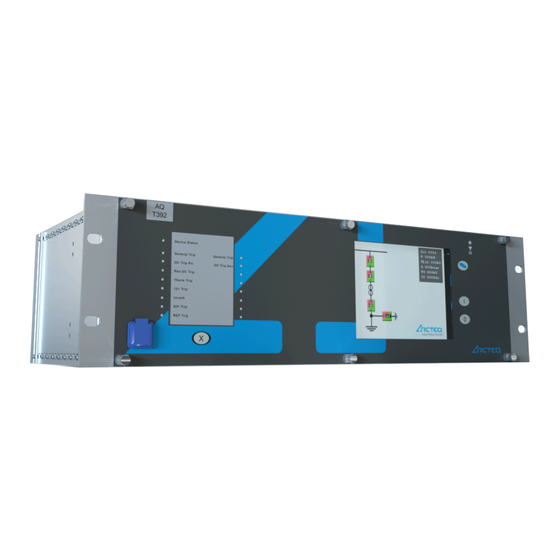
5 IED user interface A A Q Q -T3x -T3xx x 5.1 Front panel Instruction manual Version: 2.00 5 IED user interface 5.1 Front panel The figure below presents the front panel structure for AQ-300 series units, while the table below the image describes the functions of the front panel's various elements. -
Page 12: Led Assignment
A A Q Q -T3x -T3xx x 5 IED user interface Instruction manual 5.2 LED assignment Version: 2.00 Function Description The device has four (4) capacitive operational buttons: • "X" (below the LED label) latches and resets the LEDs. Operation •... - Page 13 5 IED user interface A A Q Q -T3x -T3xx x 5.3 Touch screen Instruction manual Version: 2.00 The image below depicts the main screen of the front panel as well as the "ON", "OFF" and "Change screen" buttons. Figure. 5.3 - 2. The main menu and three operation buttons. The t The touch scr ouch screen...
- Page 14 A A Q Q -T3x -T3xx x 5 IED user interface Instruction manual 5.3 Touch screen Version: 2.00 Figure. 5.3 - 3. Lock status indicator, as displayed in the main menu. The lock sta lock stat t us indic us indica a t t or or shows whether a password is required to unlock the device before parameters or settings can be changed.
- Page 15 5 IED user interface A A Q Q -T3x -T3xx x 5.3 Touch screen Instruction manual Version: 2.00 Figure. 5.3 - 4. The password input screen. NOTICE! TICE! The lock icon is displayed even when the device has no password! Parameter menu In the parameters menu (below) you can view, set and edit certain parameters within the device.
- Page 16 A A Q Q -T3x -T3xx x 5 IED user interface Instruction manual 5.3 Touch screen Version: 2.00 Figure. 5.3 - 5. The parameter set menu. The A A ctiv ctiva a t t e but e butt t on on activated the selected parameter set, which the device will now use.
- Page 17 5 IED user interface A A Q Q -T3x -T3xx x 5.3 Touch screen Instruction manual Version: 2.00 • Floating-point number A number with a decimal point, entered with the number pad. Please note that the pad has the decimal point available only when the value can be entered as a floating-point number! •...
- Page 18 A A Q Q -T3x -T3xx x 5 IED user interface Instruction manual 5.3 Touch screen Version: 2.00 Online measurement menu The online measurement menu displays real-time data depending on what is connected to the device. When you have selected a specific function block from the online functions list, clicking the V V ie iew w but butt t on takes you to a new window that displays the parameters and their current values.
- Page 19 5 IED user interface A A Q Q -T3x -T3xx x 5.3 Touch screen Instruction manual Version: 2.00 Figure. 5.3 - 9. Event structure. NOTICE! TICE! The events menu does no not t display the whole event log, only the first few hundred items in the log! System settings menu Figure.
- Page 20 A A Q Q -T3x -T3xx x 5 IED user interface Instruction manual 5.3 Touch screen Version: 2.00 Table. 5.3 - 5. The system settings. Setting Description System parameters and station bus settings Please contact your local network administrator for further information about these (IP address, settings.
-
Page 21: The Embedded Web Server
5 IED user interface A A Q Q -T3x -T3xx x 5.4 The embedded web server Instruction manual Version: 2.00 Figure. 5.3 - 11. Turning on Q2. (1) First, we press Q2 on the touch screen to highlight the object. This causes Q2 to start blinking for a short while;... -
Page 22: Ethernet Connections
A A Q Q -T3x -T3xx x 5 IED user interface Instruction manual 5.4 The embedded web server Version: 2.00 • provide remote or local firmware updgrades • perform administrative tasks. System requirements In order to access the device interface you need a compatible web browser as well as an Ethernet connection. - Page 23 5 IED user interface A A Q Q -T3x -T3xx x 5.4 The embedded web server Instruction manual Version: 2.00 The diagram below depicts the three (3) different CPU versions and their structures: Figure. 5.4.1 - 12. The three CPU versions. Settings needed for Ethernet connection The AQ-300 devices can only be accessed over Ethernet-based communication protocols.
- Page 24 A A Q Q -T3x -T3xx x 5 IED user interface Instruction manual 5.4 The embedded web server Version: 2.00 Make sure that your browser does NO NOT T use a proxy server while accessing an AQ-300 device. However, if there is a proxy server in your network, contact the system administrator and have them add an exception.
- Page 25 5 IED user interface A A Q Q -T3x -T3xx x 5.4 The embedded web server Instruction manual Version: 2.00 Figure. 5.4.1 - 14. Using the RJ45 connection. The crossover cable's pinout has been depicted in the diagram below: Figure. 5.4.1 - 15. The pinout of the crossover cable. Please note that the cable's RJ45 connector can also be connected to an Ethernet switch.
-
Page 26: Getting Started
A A Q Q -T3x -T3xx x 5 IED user interface Instruction manual 5.4 The embedded web server Version: 2.00 ST-type fiber optic connection The ST-type fiber optic connector of the 100Base-FX Ethernet provides a connection to an Ethernet switch with an identical fiber optic input. When using this connection, all the network's IEDs with client functionalities (e.g. - Page 27 5 IED user interface A A Q Q -T3x -T3xx x 5.4 The embedded web server Instruction manual Version: 2.00 Figure. 5.4.2 - 17. Web server elements. The menu that is currently selected is highlighted in black (in the image above, the main menu is selected).
-
Page 28: Menu Items
A A Q Q -T3x -T3xx x 5 IED user interface Instruction manual 5.4 The embedded web server Version: 2.00 5.4.3 Menu items Main menu Figure. 5.4.3 - 18. The main menu and its elements. In the main menu you can control the device's front panel. The image of a touch screen (located on the right) behaves the same way as the actual touch screen. - Page 29 5 IED user interface A A Q Q -T3x -T3xx x 5.4 The embedded web server Instruction manual Version: 2.00 Parameters menu Figure. 5.4.3 - 19. The parameters menu and its elements. You can view and change various parameters and variables in this menu. You can manage the different parameter sets by resetting, renaming, exporting and importing them.
- Page 30 A A Q Q -T3x -T3xx x 5 IED user interface Instruction manual 5.4 The embedded web server Version: 2.00 In the "Parameter set" section of the page there are options for managing the parameter sets. The section lists all the available parameter sets, and each can be manipulated with the buttons located on the right of the line.
- Page 31 5 IED user interface A A Q Q -T3x -T3xx x 5.4 The embedded web server Instruction manual Version: 2.00 Figure. 5.4.3 - 21. The system settings menu. Table. 5.4.3 - 7. The system setting sections and their content. Section name Description If enabled, the device asks you to confirm the saving of new settings by pressing the "I"...
- Page 32 A A Q Q -T3x -T3xx x 5 IED user interface Instruction manual 5.4 The embedded web server Version: 2.00 Section name Description Contain the parameters to control the LCD panel's behaviour. The light switches off after its set timeout. LCD backlight The "Backlight group"...
- Page 33 5 IED user interface A A Q Q -T3x -T3xx x 5.4 The embedded web server Instruction manual Version: 2.00 Figure. 5.4.3 - 23. Elements of the events menu. With the R R e e fr fresh esh button you can refresh the list displaying the events, the E E ra rase all e se all ev v ents ents button clears the list on the screen, and the Expor...
- Page 34 A A Q Q -T3x -T3xx x 5 IED user interface Instruction manual 5.4 The embedded web server Version: 2.00 Figure. 5.4.3 - 25. Disturbance recorder. The "Recorded disturbances" section lists all disturbance records. You can refresh the list with the R R e e fr fresh esh button to display any new disturbance records that have occurred after the page was opened or refreshed last.
- Page 35 5 IED user interface A A Q Q -T3x -T3xx x 5.4 The embedded web server Instruction manual Version: 2.00 You can set a setpoint by clicking anywhere on the graph, and the positioning the cursor to a desired second point. The preview then displays the timestamp of the first setpoint, and the time difference between the two setpoints.
- Page 36 A A Q Q -T3x -T3xx x 5 IED user interface Instruction manual 5.4 The embedded web server Version: 2.00 Advanced Figure. 5.4.3 - 29. The Advanced menu. This menu displays the additional, more advanced options. You can set a password request before a user is allowed access to these options.
- Page 37 5 IED user interface A A Q Q -T3x -T3xx x 5.4 The embedded web server Instruction manual Version: 2.00 The Ge Get r t repor eport t button generates a .zip file that has all of the log files archived together. The files have valuable information and they can help in analyzing errors and malfunctions;...
-
Page 38: Troubleshooting
A A Q Q -T3x -T3xx x 5 IED user interface Instruction manual 5.4 The embedded web server Version: 2.00 Figure. 5.4.3 - 32. Update manager. 5.4.4 Troubleshooting Some browsers have a tendency to handle and cache various JavaScript function improperly, and this may cause anomalies and errors in the interface. -
Page 39: Soft E Set T Up Up
6 Software setup A A Q Q -T3x -T3xx x 6.1 Functions included in AQ-T3xx Instruction manual Version: 2.00 6 Software setup 6.1 Functions included in AQ-T3xx In this chapter are presented the protection and control functions as well as the monitoring functions. The implemented protection functions are listed in the table below. -
Page 40: Measurements
A A Q Q -T3x -T3xx x 6 Software setup Instruction manual 6.2 Measurements Version: 2.00 Table. 6.1 - 10. Available control and monitoring functions Name Name ANSI ANSI Descrip Description tion TRC94 Trip logic Voltage transformer supervision SYN25 SYNC Synchro-check function Δf, ΔU, Δφ... - Page 41 6 Software setup A A Q Q -T3x -T3xx x 6.2 Measurements Instruction manual Version: 2.00 Figure. 6.2.1 - 33. Example connection. Table. 6.2.1 - 11. Values for the example above. Phase current CT: Ring core CT in Input I0: CT primary 100A I0CT primary 10A CT secondary 5A...
- Page 42 A A Q Q -T3x -T3xx x 6 Software setup Instruction manual 6.2 Measurements Version: 2.00 The performed basic calculation results the Fourier basic harmonic magnitude and angle and the true RMS value. These results are processed by subsequent protection function blocks and they are available for on-line displaying as well.
-
Page 43: Voltage Measurement And Scaling
6 Software setup A A Q Q -T3x -T3xx x 6.2 Measurements Instruction manual Version: 2.00 Measured value Dim. Explanation Angle Ch - I3 degree Vector position of the current in channel IL3 Current Ch - I4 A(secondary) Fourier basic component of the current in channel I4 Angle Ch - I4 degree Vector position of the current in channel I4... - Page 44 A A Q Q -T3x -T3xx x 6 Software setup Instruction manual 6.2 Measurements Version: 2.00 The connection of the first three VT secondary windings must be set to reflect actual physical connection of the main VTs. The associated parameter is “Connection U1-3“. The selection can be: Ph-N, Ph-Ph or Ph-N-Isolated.
- Page 45 6 Software setup A A Q Q -T3x -T3xx x 6.2 Measurements Instruction manual Version: 2.00 Figure. 6.2.2 - 36. Phase-to-phase connection. Ph-N Voltage: Residual voltage: Rated Primary U1-3: 20kV Rated Primary U4: 11.54A (=20kV/√3) Range: Type 100 The fourth input is reserved for zero sequence voltage or for a voltage from the other side of the circuit breaker for synchron switching.
- Page 46 A A Q Q -T3x -T3xx x 6 Software setup Instruction manual 6.2 Measurements Version: 2.00 Parameter name Title Selection range Default VT4_Ch13Nom_EPar_ Connection U1-3 Ph-N, Ph-Ph, Ph-N-Isolated Ph-N Selection of the fourth channel input: phase-to-neutral or phase-to-phase voltage VT4_Ch4Nom_EPar_ Connection U4 Ph-N,Ph-Ph Ph-Ph...
-
Page 47: Line Measurement
6 Software setup A A Q Q -T3x -T3xx x 6.2 Measurements Instruction manual Version: 2.00 Measured value Dim. Explanation Angle Ch - U2 degree Vector position of the voltage in channel UL2 Voltage Ch - U3 V(secondary) Fourier basic component of the voltage in channel UL3 Angle Ch - U3 degree Vector position of the voltage in channel UL3... - Page 48 A A Q Q -T3x -T3xx x 6 Software setup Instruction manual 6.2 Measurements Version: 2.00 The outputs of the line measurement function are • displayed measured values • reports to the SCADA system. NOTICE! TICE! The scaling values are entered as parameter setting for the “Voltage transformer input” function block and for the “Current transformer input”...
- Page 49 6 Software setup A A Q Q -T3x -T3xx x 6.2 Measurements Instruction manual Version: 2.00 Figure. 6.2.3 - 37. Measured values in a configuration for compensated networks. The available quantities are described in the configuration description documents. Reporting the measured values and the changes For reporting, additional information is needed, which is defined in parameter setting.
- Page 50 A A Q Q -T3x -T3xx x 6 Software setup Instruction manual 6.2 Measurements Version: 2.00 The selection of the reporting mode items is explained in next chapters. "Amplitude" mode of reporting If the “Amplitude” mode is selected for reporting, a report is generated if the measured value leaves the deadband around the previously reported value.
- Page 51 6 Software setup A A Q Q -T3x -T3xx x 6.2 Measurements Instruction manual Version: 2.00 Parameter name Title Dim. Step Default Range value for the apparent power MXU_SRange_FPar_ Range value - S 100000 0.01 Deadband value for the current MXU_IDeadB_FPar_ Deadband value - I 2000...
- Page 52 A A Q Q -T3x -T3xx x 6 Software setup Instruction manual 6.2 Measurements Version: 2.00 Figure. 6.2.3 - 39. Reporting when Integrated mode is selected. Periodic reporting Periodic reporting is generated independently of the changes of the measured values when the defined time period elapses.
- Page 53 6 Software setup A A Q Q -T3x -T3xx x 6.2 Measurements Instruction manual Version: 2.00 Parameter name Title Dim. Step Default Deadband value for the phase-to-neutral voltage MXU_UPhDeadB_FPar_ Deadband value - U ph-N 0.01 Range value for the phase-to-neutral voltage MXU_UPhRange_FPar_ Range value - U ph-N 1000...
-
Page 54: Measurement Connection Examples
A A Q Q -T3x -T3xx x 6 Software setup Instruction manual 6.2 Measurements Version: 2.00 6.2.4 Measurement connection examples Connection example with a current breaker Figure. 6.2.4 - 40. Connection example with a current breaker (open and closed connections, CT and VT connection). - Page 55 6 Software setup A A Q Q -T3x -T3xx x 6.2 Measurements Instruction manual Version: 2.00 Connection example with two CTs (facing) Figure. 6.2.4 - 41. Connection example with two CTs facing each other. © Arcteq Relays Ltd IM00077...
-
Page 56: Protection Functions
A A Q Q -T3x -T3xx x 6 Software setup Instruction manual 6.3 Protection functions Version: 2.00 Connection example with two CTs (inverted secondary) Figure. 6.2.4 - 42. Connection example with two CTs (the direction of the secondary side's starpoint has been inverted). - Page 57 6 Software setup A A Q Q -T3x -T3xx x 6.3 Protection functions Instruction manual Version: 2.00 Figure. 6.3.1 - 43. Operating characteristics of the instantaneous overcurrent protection function. The variables in the image above are: • t (seconds) = theoretical operating time if G>G (without additional time delay) •...
-
Page 58: Residual Instantaneous Overcurrent Protection (I0>; 50N/51N)
A A Q Q -T3x -T3xx x 6 Software setup Instruction manual 6.3 Protection functions Version: 2.00 The algorithm generates a trip command without additional time delay based on the Fourier components of the phase currents or peak values of the phase currents in case if the user set pick-up value is exceeded. -
Page 59: Three-Phase Time Overcurrent Protection (I>; 50/51)
6 Software setup A A Q Q -T3x -T3xx x 6.3 Protection functions Instruction manual Version: 2.00 The structure of the algorithm consists of following modules. Fourier calculation module calculates the RMS values of the Fourier components of the residual current. Peak selection module is an alternative for the Fourier calculation module and the peak selection module selects the peak values of the residual currents individually. - Page 60 A A Q Q -T3x -T3xx x 6 Software setup Instruction manual 6.3 Protection functions Version: 2.00 Figure. 6.3.3 - 47. The structure of the time overcurrent algorithm. The algorithm generates a start signal based on the Fourier components of the phase currents or peak values of the phase currents in case if the user set pick-up value is exceeded.
- Page 61 6 Software setup A A Q Q -T3x -T3xx x 6.3 Protection functions Instruction manual Version: 2.00 The variables of the equation above are: • t(G) (seconds) = theoretical operate time with constant value of G, when G>G • k, c = contants characterizing the selected curve •...
- Page 62 A A Q Q -T3x -T3xx x 6 Software setup Instruction manual 6.3 Protection functions Version: 2.00 Figure. 6.3.3 - 49. IEC - NI operating curves with minimum and maximum pick-up settings and TMS settings from 0.05 to 20. Figure. 6.3.3 - 50. IEC - VI operating curves with minimum and maximum pick-up settings and TMS settings from 0.05 to 20.
- Page 63 6 Software setup A A Q Q -T3x -T3xx x 6.3 Protection functions Instruction manual Version: 2.00 Figure. 6.3.3 - 51. IEC - EI operating curves with minimum and maximum pick-up settings and TMS settings from 0.05 to 20. Figure. 6.3.3 - 52. IEC - LTI operating curves with minimum and maximum pick-up settings and TMS settings from 0.05 to 20.
- Page 64 A A Q Q -T3x -T3xx x 6 Software setup Instruction manual 6.3 Protection functions Version: 2.00 Figure. 6.3.3 - 53. IEEE/ANSI - NI operating curves with minimum and maximum pick-up settings and TMS settings from 0.05 to 20. Figure. 6.3.3 - 54. IEEE/ANSI - MI operating curves with minimum and maximum pick-up settings and TMS settings from 0.05 to 20.
- Page 65 6 Software setup A A Q Q -T3x -T3xx x 6.3 Protection functions Instruction manual Version: 2.00 Figure. 6.3.3 - 55. IEEE/ANSI - VI operating curves with minimum and maximum pick-up settings and TMS settings from 0.05 to 20. Figure. 6.3.3 - 56. IEEE/ANSI - EI operating curves with minimum and maximum pick-up settings and TMS settings from 0.05 to 20.
- Page 66 A A Q Q -T3x -T3xx x 6 Software setup Instruction manual 6.3 Protection functions Version: 2.00 Figure. 6.3.3 - 57. IEEE/ANSI - LTI operating curves with minimum and maximum pick-up settings and TMS settings from 0.05 to 20. Figure. 6.3.3 - 58. IEEE/ANSI - LTVI operating curves with minimum and maximum pick-up settings and TMS settings from 0.05 to 20.
- Page 67 6 Software setup A A Q Q -T3x -T3xx x 6.3 Protection functions Instruction manual Version: 2.00 Figure. 6.3.3 - 59. IEEE/ANSI - LTEI operating curves with minimum and maximum pick-up settings and TMS settings from 0.05 to 20. Resetting characteristics for the function depends on the selected operating time characteristics. For the IEC type IDMT characteristics the reset time is user settable and for the ANSI/IEEE type characteristics the resetting time follows equation below.
- Page 68 A A Q Q -T3x -T3xx x 6 Software setup Instruction manual 6.3 Protection functions Version: 2.00 Table. 6.3.3 - 27. Parameters and operating curve types for the IDMT characteristics. Curve family Characteristics α NI (normally inverse) VI (very inverse) User settable fixed reset time EI (extremely inverse) LTI (long time inverse)
-
Page 69: Residual Time Overcurrent Protection (I0>; 50N/51N)
6 Software setup A A Q Q -T3x -T3xx x 6.3 Protection functions Instruction manual Version: 2.00 Setting Parameter value Step Default Description / range Settable reset delay for definite time function and IEC IDMT Reset 0…60 000 100 ms operating characteristics. - Page 70 A A Q Q -T3x -T3xx x 6 Software setup Instruction manual 6.3 Protection functions Version: 2.00 Figure. 6.3.4 - 61. Structure of the residual time overcurrent protection algorithm. The algorithm generates a start signal based on the Fourier components of the residual current in case if the user set pick-up value is exceeded.
-
Page 71: Current Unbalance Protection (60)
6 Software setup A A Q Q -T3x -T3xx x 6.3 Protection functions Instruction manual Version: 2.00 6.3.5 Current unbalance protection (60) The current unbalance protection function can be applied to detect unexpected asymmetry in current measurement. The applied method selects maximum and minimum phase currents (fundamental Fourier components). -
Page 72: Restricted Earth Fault Protection
A A Q Q -T3x -T3xx x 6 Software setup Instruction manual 6.3 Protection functions Version: 2.00 The function can be disabled by parameter setting, and by an input signal programmed by the user. The trip command is generated after the set defined time delay. Table. - Page 73 6 Software setup A A Q Q -T3x -T3xx x 6.3 Protection functions Instruction manual Version: 2.00 • the binary output status signal • the measured values for displaying. The software modules of the differential protection function: • Fourier calculations These modules calculate the basic Fourier current components of the phase currents and that of the neutral current individually.
- Page 74 A A Q Q -T3x -T3xx x 6 Software setup Instruction manual 6.3 Protection functions Version: 2.00 Figure. 6.3.6 - 66. Principal scheme of directional decision. Zero sequence differential characteristics This module performs the necessary calculations for the evaluation of the “percentage differential characteristics”, and decides if the differential current is above the characteristic curve of the zero sequence differential protection function.
-
Page 75: Circuit Breaker Failure Protection (Cbfp; 50Bf/52Bf)
6 Software setup A A Q Q -T3x -T3xx x 6.3 Protection functions Instruction manual Version: 2.00 Setting Parameter Step Default Description value/range Directional Enabling the directional checking of the measured and check calculated zero sequence currents. TR Primary 20…500 % 100 % Phase current CT compensation. - Page 76 A A Q Q -T3x -T3xx x 6 Software setup Instruction manual 6.3 Protection functions Version: 2.00 Figure. 6.3.7 - 68. Operation logic of the CBFP function. Table. 6.3.7 - 32. Setting parameters of the CBFP function. Setting Parameter value / Step Default Description range...
-
Page 77: Overvoltage Protection (U>; 59)
6 Software setup A A Q Q -T3x -T3xx x 6.3 Protection functions Instruction manual Version: 2.00 6.3.8 Overvoltage protection (U>; 59) The overvoltage protection function measures three phase to ground voltages. If any of the measured voltages is above the pick-up setting, a start signal is generated for the phases individually. Figure. -
Page 78: Residual Overvoltage Protection (U0>; 59N)
A A Q Q -T3x -T3xx x 6 Software setup Instruction manual 6.3 Protection functions Version: 2.00 Figure. 6.3.9 - 70. The principal structure of the undervoltage function. The general start signal is set active if the voltage of any of the three measured voltages is below the level defined by pick-up setting value. -
Page 79: Thermal Overload Protection (T>; 49)
6 Software setup A A Q Q -T3x -T3xx x 6.3 Protection functions Instruction manual Version: 2.00 Figure. 6.3.10 - 71. The principal structure of the residual overvoltage function. The general start signal is set active if the measured residual voltage is above the level defined by pick- up setting value. - Page 80 A A Q Q -T3x -T3xx x 6 Software setup Instruction manual 6.3 Protection functions Version: 2.00 Figure. 6.3.11 - 72. The principal structure of the thermal overload function. In the figure above is presented the principal structure of the thermal overload function. Theinputs of the function are the maximum of TRMS values of the phase currents, ambienttemperature setting, binary input status signals and setting parameters.
-
Page 81: Transformer Differential Protection (87T)
6 Software setup A A Q Q -T3x -T3xx x 6.3 Protection functions Instruction manual Version: 2.00 Setting Parameter value / Step Default Description range Rated 60…200 Rated temperature of the protected object. temperature Base Rated ambient temperature of the device related to allowed 0…40 deg 40 deg temperature... - Page 82 A A Q Q -T3x -T3xx x 6 Software setup Instruction manual 6.3 Protection functions Version: 2.00 • Sampled values of three primary side phase currents • Sampled values of three secondary side phase currents • Sampled values of three tertiary side phase currents (in DIF87_3w version only AQ-T393) •...
- Page 83 6 Software setup A A Q Q -T3x -T3xx x 6.3 Protection functions Instruction manual Version: 2.00 Vector shift compensation The three-phase power transformers transform the primary current to the secondary side according to the turns ratio and the vector group of the transformers. The Y (star), D (delta) or Z (zig-zag) connection of the three phase coils on the primary and secondary sides causes the vector shift of the currents.
- Page 84 A A Q Q -T3x -T3xx x 6 Software setup Instruction manual 6.3 Protection functions Version: 2.00 Conn. Code Transformation of the primary side currents Transformation of the secondary side currents Group Dy11 Dz10 © Arcteq Relays Ltd IM00077...
- Page 85 6 Software setup A A Q Q -T3x -T3xx x 6.3 Protection functions Instruction manual Version: 2.00 Conn. Code Transformation of the primary side currents Transformation of the secondary side currents Group Yd11 Yz11 The differential currents are calculated using the (RSTshift) values and the (TR primary) and (TR secondary) parameters, defined by the turns ratio of the transformer and that of the current transformers, resulting in the currents marked with an apostrophe (’).
- Page 86 A A Q Q -T3x -T3xx x 6 Software setup Instruction manual 6.3 Protection functions Version: 2.00 The current measuring software modules process these momentary values of the differential currents and calculate values that are proportional to the RMS values. Operation with the zero sequence current in case of a phase-to-ground fault on the delta side On the secondary side of a high voltage /medium voltage transformer which is connected in delta on...
- Page 87 6 Software setup A A Q Q -T3x -T3xx x 6.3 Protection functions Instruction manual Version: 2.00 The harmonic analysis block of modules consists of two sub-blocks, one for the second harmonic decision and one for the fifth harmonic decision. Each sub-block includes three individual software modules for the phases.
- Page 88 A A Q Q -T3x -T3xx x 6 Software setup Instruction manual 6.3 Protection functions Version: 2.00 Figure. 6.3.12 - 75. Operating principle of the current restraint and non-restraint characteristics. Setting parameters Table. 6.3.12 - 38. Setting parameters of the differential protection function. Parameter Setting value/range Step Default Description...
- Page 89 6 Software setup A A Q Q -T3x -T3xx x 6.3 Protection functions Instruction manual Version: 2.00 Parameter Setting value/range Step Default Description 5th Harm. Ratio 5…50 % 25 % Parameter of the fifth harmonic restraint. Basic pick-up setting for the current restraint Base sensitivity 10…50 % 20 %...
-
Page 90: Overfrequency Protection (F>; 81O)
A A Q Q -T3x -T3xx x 6 Software setup Instruction manual 6.3 Protection functions Version: 2.00 (This is a direct consequence of selecting TR primary; this is the current of the secondary side current transformer related to the rated current of the CT.) The code value of the transformer’s connection group (Yd11): Pri-Sec VGroup = Yd11 Fixed trip assignment into trip logic... -
Page 91: Underfrequency Protection (F<; 81U)
6 Software setup A A Q Q -T3x -T3xx x 6.3 Protection functions Instruction manual Version: 2.00 The frequency measurement is based on channel No. 1 (line voltage) and channel No. 4 (busbar voltage) of the voltage input module. In some applications, the frequency is measured based on the weighted sum of the phase voltages. -
Page 92: Rate-Of-Change Of Frequency Protection (Fd/Ft>/<; 81R)
A A Q Q -T3x -T3xx x 6 Software setup Instruction manual 6.3 Protection functions Version: 2.00 Table. 6.3.14 - 40. Setting parameters of the underfrequency protection function. Setting value Parameter Step Default Description / range Operating mode selection for the function. Operation can be Operation either enabled "On"... -
Page 93: Overexcitation (V/H>; 24)
6 Software setup A A Q Q -T3x -T3xx x 6.3 Protection functions Instruction manual Version: 2.00 Setting Parameter value / Step Default Description range 0…60 000 Operating time delay setting for the “Trip” signal from the“Start” Time delay 200 ms signal. - Page 94 A A Q Q -T3x -T3xx x 6 Software setup Instruction manual 6.3 Protection functions Version: 2.00 The magnitude can be calculated if at least one positive and one negative peak value have been found, and the function starts if the calculated flux magnitude is above the setting value. Accordingly, the starting delay of the function depends on the frequency: if the frequency is low, more time is needed to reach the opposite peak value.
- Page 95 6 Software setup A A Q Q -T3x -T3xx x 6.3 Protection functions Instruction manual Version: 2.00 R R ese eset time t time t(G) = t (when G<0.95*G Drop-off where: (seconds) = the drop-off time if G<0.95*G , fix value drop-off IEEE standar IEEE standard dependent time charact...
- Page 96 A A Q Q -T3x -T3xx x 6 Software setup Instruction manual 6.3 Protection functions Version: 2.00 Figure. 6.3.16 - 79. IEEE standard dependent time characteristics (enlarged). This inverse type characteristic is also combined with a minimum time delay, the value of which is set by user parameter VPH24_MinDel_TPar_ (Min.
- Page 97 6 Software setup A A Q Q -T3x -T3xx x 6.3 Protection functions Instruction manual Version: 2.00 Figure. 6.3.16 - 80. Structure of the overexcitation protection function. The inputs are • The sampled values of a line-to-line voltage (ULL) • Parameters •...
- Page 98 A A Q Q -T3x -T3xx x 6 Software setup Instruction manual 6.3 Protection functions Version: 2.00 Table. 6.3.16 - 42. Binary status signals. Binary output signals Signal title Explanation VPH24_GenSt_GrI_ General Start General starting of the function VPH24_GenTr_GrI_ General Trip General trip command of the function Binary sta Binary stat t us signal...
-
Page 99: Inrush Current Detection (68)
6 Software setup A A Q Q -T3x -T3xx x 6.4 Control, monitoring and measurements Instruction manual Version: 2.00 Setting Parameter value / Step Default Description range Min Time 0.01 Minimum time delay for inverse time characteristics or delay for the 0.5…60 s 10 s Delay... - Page 100 A A Q Q -T3x -T3xx x 6 Software setup Instruction manual 6.4 Control, monitoring and measurements Version: 2.00 1. The W 1. The WARNING signal of the de ARNING signal of the device vice The AQ300 series devices have several LED-s on the front panel. The upper left LED indicates the state of the device: •...
- Page 101 6 Software setup A A Q Q -T3x -T3xx x 6.4 Control, monitoring and measurements Instruction manual Version: 2.00 Figure. 6.4.1 - 83. The function block of the common function block. Table. 6.4.1 - 45. The binary output status signals. Binary output status signal Title Explanation...
-
Page 102: Trip Logic (94)
A A Q Q -T3x -T3xx x 6 Software setup Instruction manual 6.4 Control, monitoring and measurements Version: 2.00 Binary input status signal Title Explanation Common_Remote4_GrI_ Remote 4 Output 4 to indicate the state of group 4 as Remote Fix signal FALSE to be applied in the graphic logic editor, if Common_FixFalse_GrI_ False needed... - Page 103 6 Software setup A A Q Q -T3x -T3xx x 6.4 Control, monitoring and measurements Instruction manual Version: 2.00 Application example Figure. 6.4.2 - 85. Example picture where two I> TOC51 and I0> TOC51N trip signals are connected to two trip logic function blocks.
-
Page 104: Voltage Transformer Supervision (Vts)
A A Q Q -T3x -T3xx x 6 Software setup Instruction manual 6.4 Control, monitoring and measurements Version: 2.00 Trip contact connections for wirings can be found in Hardware configuration under Rack designer → Preview or in Connection allocations. During the parameter setting phase it should be taken care that the trip logic blocks are activated. The parameters are described in the following table. - Page 105 6 Software setup A A Q Q -T3x -T3xx x 6.4 Control, monitoring and measurements Instruction manual Version: 2.00 Figure. 6.4.3 - 88. Operation logic of the voltage transformer supervision and dead line detection. The voltage transformer supervision logic operates through decision logic presented in the following figure.
-
Page 106: Current Transformer Supervision (Cts)
A A Q Q -T3x -T3xx x 6 Software setup Instruction manual 6.4 Control, monitoring and measurements Version: 2.00 Figure. 6.4.3 - 90. The function block of the voltage transformer supervision function. The binary input and output status signals of voltage transformer supervision function are listed in tables below. -
Page 107: Synchrocheck (Dv/Da/Df; 25)
6 Software setup A A Q Q -T3x -T3xx x 6.4 Control, monitoring and measurements Instruction manual Version: 2.00 The function can be disabled by parameter setting, and by an input signal programmed by the user. The failure signal is generated after the defined time delay. The function block of the current transformer supervision function is shown in figure bellow. - Page 108 A A Q Q -T3x -T3xx x 6 Software setup Instruction manual 6.4 Control, monitoring and measurements Version: 2.00 The conditions for safe closing are as follows: • The difference of the voltage magnitudes is below the set limit. • The difference of the frequencies is below the set limit. •...
- Page 109 6 Software setup A A Q Q -T3x -T3xx x 6.4 Control, monitoring and measurements Instruction manual Version: 2.00 Figure. 6.4.5 - 92. Operation logic of the synchrocheck function. The synchro check/synchro switch function contains two kinds of software blocks: •...
- Page 110 A A Q Q -T3x -T3xx x 6 Software setup Instruction manual 6.4 Control, monitoring and measurements Version: 2.00 If the active bus section changes the function is dynamically blocked for 1000ms and no release signal or switching command is generated. The processed line voltage is selected based on the preset parameter (Voltage select).
- Page 111 6 Software setup A A Q Q -T3x -T3xx x 6.4 Control, monitoring and measurements Instruction manual Version: 2.00 If the conditions are fulfilled for at least 45 ms, then the function generates a release output signal (Release Auto/Manual).If the conditions for synchro check operation are not fulfilled and a close request is received as the input signal (SySwitch Auto/Manual), then synchro switching is attempted.
- Page 112 A A Q Q -T3x -T3xx x 6 Software setup Instruction manual 6.4 Control, monitoring and measurements Version: 2.00 Binary status signal Title Explanation Cancel SYN25_CancelM_GrO_ Signal to interrupt (cancel) the manual switching procedure. Manual Table. 6.4.5 - 54. The binary output signals. Binary status signal Title Explanation...
- Page 113 6 Software setup A A Q Q -T3x -T3xx x 6.4 Control, monitoring and measurements Instruction manual Version: 2.00 Setting Parameter value/ Step Default Description range Breaker operating time at closing. This parameter is used for the synchroswitch closing command compensation and it Breaker Time 0…500 ms 80 ms...
-
Page 114: Integrated Automatic Voltage Regulator (Avr)
A A Q Q -T3x -T3xx x 6 Software setup Instruction manual 6.4 Control, monitoring and measurements Version: 2.00 Setting Parameter value/ Step Default Description range Manual synchroswitching selection. Selection may be enabled SynSW Man "On" or disabled "Off". Deadbus Energizing mode of manual synchroswitching. - Page 115 6 Software setup A A Q Q -T3x -T3xx x 6.4 Control, monitoring and measurements Instruction manual Version: 2.00 The “Operation” parameter for selection of the operating mode has several choices: • Off, for disabling the control function • Single, for regulation a single transformer only •...
- Page 116 A A Q Q -T3x -T3xx x 6 Software setup Instruction manual 6.4 Control, monitoring and measurements Version: 2.00 Figure. 6.4.6 - 96. The logic schema of the automatic tap changer controller Automatic control mode V V olta oltage compensa ge compensation in a tion in aut utoma omatic contr...
- Page 117 6 Software setup A A Q Q -T3x -T3xx x 6.4 Control, monitoring and measurements Instruction manual Version: 2.00 , where (R) Compound Factor is a parameter value. If the “|I|” current is above the value defined by the parameter “I Comp Limit”, then in the formulas above this preset value is considered instead of the higher values measured.
- Page 118 A A Q Q -T3x -T3xx x 6 Software setup Instruction manual 6.4 Control, monitoring and measurements Version: 2.00 Figure. 6.4.6 - 97. Voltage level settings. T T ime dela ime delay in a y in aut utoma omatic contr tic control mode ol mode In automatic control mode the first and every subsequent control command is processed separately.
- Page 119 6 Software setup A A Q Q -T3x -T3xx x 6.4 Control, monitoring and measurements Instruction manual Version: 2.00 • "Inverse": the standard IDMT characteristic defined by the parameters: ◦ T1: the maximum delay defined by the parameter ◦ "U Deadband": the width of the permitted range in both + and – directions ◦...
- Page 120 A A Q Q -T3x -T3xx x 6 Software setup Instruction manual 6.4 Control, monitoring and measurements Version: 2.00 • TCDrive the supervision is based on the input “TCRun”. In this case, after command generation the drive is expected to start operation within one quarter of the value defined by the parameter “Max Operating Time”...
- Page 121 6 Software setup A A Q Q -T3x -T3xx x 6.4 Control, monitoring and measurements Instruction manual Version: 2.00 Table. 6.4.6 - 57. Outputs of the ATCC function block. Title Explanation AutoBlocked Automatic control blocked Manual Signaling the manual mode of operation Higher Command Command for increasing the voltage Lower Command...
- Page 122 A A Q Q -T3x -T3xx x 6 Software setup Instruction manual 6.4 Control, monitoring and measurements Version: 2.00 Title Explanation TCRun Running state of the tap changer Reset Reset to release from blocked state BlkProc Blocking signal from the tap changer VRed1 Reduced voltage 1 is required VRed2...
- Page 123 6 Software setup A A Q Q -T3x -T3xx x 6.4 Control, monitoring and measurements Instruction manual Version: 2.00 Table. 6.4.6 - 62. Setting parameters of the automatic tap changer controller function (timer parameters). Timer parameter Unit Step Default Timer parameter description name Time limit for tap change Max operating time...
-
Page 124: Switch-On-To-Fault
A A Q Q -T3x -T3xx x 6 Software setup Instruction manual 6.4 Control, monitoring and measurements Version: 2.00 Float parameter name Unit Digits Default Float parameter description Voltage lower limit to disable all U Low Block 50.0 100.0 70.0 operation. - Page 125 6 Software setup A A Q Q -T3x -T3xx x 6.4 Control, monitoring and measurements Instruction manual Version: 2.00 Figure. 6.4.7 - 99. The scheme of the switch-on-to-fault preparation. The binary input signals of the “switch-onto-fault” detection function are: • CBClose Manual close command to the circuit breaker. •...
-
Page 126: Disturbance Recorder
A A Q Q -T3x -T3xx x 6 Software setup Instruction manual 6.4 Control, monitoring and measurements Version: 2.00 6.4.8 Disturbance recorder The disturbance recorder function can record analog signals and binary status signals. These signals are user configurable. The disturbance recorder function has a binary input signal, which serves the purpose of starting the function. -
Page 127: Event Recorder
6 Software setup A A Q Q -T3x -T3xx x 6.4 Control, monitoring and measurements Instruction manual Version: 2.00 Table. 6.4.8 - 67. Setting parameters. Parameter Setting value/range Step Default Description Operation Function enbaling / disabling. PreFault 100…500 ms 1 ms 200 ms Pre triggering time included in the recording. - Page 128 A A Q Q -T3x -T3xx x 6 Software setup Instruction manual 6.4 Control, monitoring and measurements Version: 2.00 D D ir irectional o ectional ov v er ercurr current pr ent pro o t t ection function (T ection function (TOC67) hig OC67) high h se set t ting sta ting stage Start L1...
- Page 129 6 Software setup A A Q Q -T3x -T3xx x 6.4 Control, monitoring and measurements Instruction manual Version: 2.00 Low Start L1 Low setting stage start signal in phase L1 Low Start L2 Low setting stage start signal in phase L2 Low Start L3 Low setting stage start signal in phase L3 Low General Start...
- Page 130 A A Q Q -T3x -T3xx x 6 Software setup Instruction manual 6.4 Control, monitoring and measurements Version: 2.00 Close_Auto Close command in automatic mode of operation Released Man The function releases manual close command In progress Man The manual close command is in progress Close_Man Close command in manual mode of operation A A ut utoma...
-
Page 131: Measured Values
6 Software setup A A Q Q -T3x -T3xx x 6.4 Control, monitoring and measurements Instruction manual Version: 2.00 Local Local mode of operation Operation counter Operation counter DC OPCap D D isconnect isconnector Ear or Earth th Status value Status of the earthing switch Enable Close Close command is enabled... - Page 132 A A Q Q -T3x -T3xx x 6 Software setup Instruction manual 6.4 Control, monitoring and measurements Version: 2.00 Analog value Explanation Angle Ch – U4 Phase angle of the Fourier fundamental harmonic voltage component in Channel U4* C C T4 mod T4 module Current Ch –...
-
Page 133: Status Monitoring For Switching Devices
6 Software setup A A Q Q -T3x -T3xx x 6.4 Control, monitoring and measurements Instruction manual Version: 2.00 Analog value Explanation Voltage L2 True RMS value of the voltage in phase L2 Voltage L3 True RMS value of the voltage in phase L3 Voltage L12 True RMS value of the voltage in phase L1L2 Voltage L23... -
Page 134: Sy Y St Stem Int 7 S Em Integra Egration Tion
A A Q Q -T3x -T3xx x 7 System integration Instruction manual 6.4 Control, monitoring and measurements Version: 2.00 7 System integration The AQ T3xx contains two ports for communicating to upper level supervisory system and one for process bus communication. The physical media or the ports can be either serial fiber optic or RJ 45 or Ethernet fiber optic. -
Page 135: Block Diagrams
8 Connections A A Q Q -T3x -T3xx x 8.1 Block diagrams Instruction manual Version: 2.00 8 Connections 8.1 Block diagrams NOTICE! TICE! The structure of both AQ-T352 (the half-rack version) and AQ-T392 (the full rack version) is the same, except AQ-T392 has more option card slots available. The structure of both AQ-T353 (the half-rack version) and AQ-T393 (the full rack version) is the same, except AQ-T393 has more option card slots available. - Page 136 A A Q Q -T3x -T3xx x 8 Connections Instruction manual 8.1 Block diagrams Version: 2.00 Block diagram of AQ-T352 with all options Figure. 8.1 - 103. Block diagram of AQ-T352 with all options installed. O12+ 1101 PS+ 1030 DI 1 AQ-T352 DI 2 DI 3...
- Page 137 8 Connections A A Q Q -T3x -T3xx x 8.1 Block diagrams Instruction manual Version: 2.00 Block diagram of AQ-T393 with minimum options Figure. 8.1 - 104. Block diagram of AQ-T393 with minimum options installed. O12+ 1101 PS+ 1030 DI 1 DI 2 DI 3 DI 4...
- Page 138 A A Q Q -T3x -T3xx x 8 Connections Instruction manual 8.1 Block diagrams Version: 2.00 Block diagram of AQ-T393 with all options Figure. 8.1 - 105. Block diagram of AQ-T393 with all options installed. O12+ 1101 PS+ 1030 DI 1 DI 2 DI 3 DI 4...
-
Page 139: Arcteq Relays Ltd
8 Connections A A Q Q -T3x -T3xx x 8.2 Connection example Instruction manual Version: 2.00 8.2 Connection example Figure. 8.2 - 106. Connection example of AQ-T352 transformer protection IED. © Arcteq Relays Ltd IM00077... - Page 140 A A Q Q -T3x -T3xx x 8 Connections Instruction manual 8.2 Connection example Version: 2.00 Figure. 8.2 - 107. Connection example of AQ-T393 transformer protection IED. © Arcteq Relays Ltd IM00077...
-
Page 141: Construction And Installation Tion
9 Construction and installation A A Q Q -T3x -T3xx x 9.1 Construction Instruction manual Version: 2.00 9 Construction and installation 9.1 Construction Contruction and installation of AQ-T352 The AQ-T352 transformer protection IED consists of hardware modules. Due to modular structure optional positions for the slots can be user defined in the ordering of the IED to include I/O modules and other types of additional modules. - Page 142 A A Q Q -T3x -T3xx x 9 Construction and installation Instruction manual 9.1 Construction Version: 2.00 Position Module identifier Explanation R8+ 00 Binary output module, 8 output contacts CPU+ 1201 Processor and communication module H, I Spare — Contruction and installation of AQ-T392 The AQ-T392 transformer protection IED consists of hardware modules.
-
Page 143: Cpu Module
9 Construction and installation A A Q Q -T3x -T3xx x 9.2 CPU module Instruction manual Version: 2.00 The AQ-T393 transformer protection IED consists of hardware modules. Due to modular structure optional positions for the slots can be user defined in the ordering of the IED to include I/O modules and other types of additional modules. -
Page 144: Power Supply Module
A A Q Q -T3x -T3xx x 9 Construction and installation Instruction manual 9.3 Power supply module Version: 2.00 After power-up the RDSP processor starts up with the previously saved configuration and parameters. Generally, the power-up procedure for the RDSP and relay functions takes approx. 1 sec. That is to say, it is ready to trip within this time. -
Page 145: Binary Input Module(S)
9 Construction and installation A A Q Q -T3x -T3xx x 9.4 Binary input module(s) Instruction manual Version: 2.00 9.4 Binary input module(s) Figure. 9.4 - 112. The binary input module O12+ 1101. The inputs are galvanic isolated and the module converts high-voltage signals to the voltagelevel and format of the internal circuits. -
Page 146: Binary Output Module(S)
A A Q Q -T3x -T3xx x 9 Construction and installation Instruction manual 9.5 Binary output module(s) Version: 2.00 9.5 Binary output module(s) Figure. 9.5 - 113. The binary output module R8+ 80. The signaling output modules can be ordered as 8 relay outputs with dry contacts. The binary output modules are: •... -
Page 147: Milliampere Module
9 Construction and installation A A Q Q -T3x -T3xx x 9.6 Milliampere module Instruction manual Version: 2.00 9.6 Milliampere module Figure. 9.6 - 114. The milliampere (mA) input module AIC +0200. The analog input module accepts transducers current outputs. The AIC module can measure unipolar and bipolar current values in wide ranges. -
Page 148: Tripping Module
A A Q Q -T3x -T3xx x 9 Construction and installation Instruction manual 9.7 Tripping module Version: 2.00 9.7 Tripping module Figure. 9.7 - 115. The tripping module TRIP+ 2101. The tripping module applies direct control of a circuit breaker. The module provides fast operation and is rated for heavy duty controlling. -
Page 149: Voltage Measurement Module
9 Construction and installation A A Q Q -T3x -T3xx x 9.8 Voltage measurement module Instruction manual Version: 2.00 9.8 Voltage measurement module Figure. 9.8 - 116. The voltage measurement module VT+ 2211. For voltage related functions (over- /under -voltage, directional functions, distance function,power functions) or disturbance recorder functionality this module is needed. -
Page 150: Current Measurement Module
A A Q Q -T3x -T3xx x 9 Construction and installation Instruction manual 9.9 Current measurement module Version: 2.00 9.9 Current measurement module Figure. 9.9 - 117. Connector allocation of the current measurement module. Current measurement module is used for measuring current transformer output current. Module includes three phase current inputs and one zero sequence current input. -
Page 151: Installation And Dimensions
9 Construction and installation A A Q Q -T3x -T3xx x 9.10 Installation and dimensions Instruction manual Version: 2.00 9.10 Installation and dimensions Figure. 9.10 - 118. Dimensions of AQ-x35x IED. © Arcteq Relays Ltd IM00077... - Page 152 A A Q Q -T3x -T3xx x 9 Construction and installation Instruction manual 9.10 Installation and dimensions Version: 2.00 Figure. 9.10 - 119. Panel cut-out and spacing of AQ-x35x IED. Figure. 9.10 - 120. Dimensions of AQ-x39x IED. © Arcteq Relays Ltd IM00077...
- Page 153 9 Construction and installation A A Q Q -T3x -T3xx x 9.10 Installation and dimensions Instruction manual Version: 2.00 Figure. 9.10 - 121. Panel cut-out and spacing of AQ-x39x IED. © Arcteq Relays Ltd IM00077...
-
Page 154: Technic Echnical Da Al Data Ta
A A Q Q -T3x -T3xx x 10 Technical data Instruction manual 10.1 Protection functions Version: 2.00 10 Technical data 10.1 Protection functions Breaker failure protection function CBFP, (50BF) Current inaccuracy <2 % Re-trip time Approx. 15ms Operation time inaccuracy + 5ms Current reset time 20ms... - Page 155 10 Technical data A A Q Q -T3x -T3xx x 10.1 Protection functions Instruction manual Version: 2.00 Pickup time 25 – 30ms Residual instantaneous overcurrent protection I0> (50N) Operating characteristic Instantaneous Picku-up current inaccuracy <2% Reset ratio 0.95 Operate time at 2*In <15 ms Peak value calculation <25 ms...
- Page 156 A A Q Q -T3x -T3xx x 10 Technical data Instruction manual 10.1 Protection functions Version: 2.00 Residual overvoltage protection function U0> (59N) Pick-up starting inaccuracy < 0,5 % Reset time 50 ms U> → Un 40 ms U> → 0 Operate time inaccuracy + 15 ms Overfrequency protection function f>...
-
Page 157: Control Functions
10 Technical data A A Q Q -T3x -T3xx x 10.2 Control functions Instruction manual Version: 2.00 Voltage range 10…170V secondary Voltage measurement inaccuracy <1% (0.5 – 1.2xUn) Frequency measurement inaccuracy <1% (0.8 – 1.2xfn) Differential protection (87) Operating characteristic 2 breakpoint Characteristics inaccuracy <2%... -
Page 158: Monitoring Functions
A A Q Q -T3x -T3xx x 10 Technical data Instruction manual 10.3 Monitoring functions Version: 2.00 Inverse and “2powerN” time delay 12% < DU < 25% <5% 25% < DU < 50% 2% or +/- 20ms, whichever is greater Synchroncheck function du/df (25) Rated Voltage Un 100/200V, setting parameter... - Page 159 10 Technical data A A Q Q -T3x -T3xx x 10.4 Hardware Instruction manual Version: 2.00 Current measurement module 1/5A (parameter settable) Nominal current 0.2A (ordering option) Number of channels per module 50Hz Rated frequency 60Hz (ordering option) Burden <0.1VA at rated current 20A (continuous) Thermal withstand 500A (for 1s)
-
Page 160: Tests And Environmental Conditions
A A Q Q -T3x -T3xx x 10 Technical data Instruction manual 10.5 Tests and environmental conditions Version: 2.00 Breaking capacity 0.2A (L/R=40ms, 220Vdc) Binary output module Rated voltage Un 250Vac/dc Number of outputs per module 7 (NO) + 1(NC) Continuous carry Breaking capacity 0.2A (L/R=40ms, 220Vdc) - Page 161 10 Technical data A A Q Q -T3x -T3xx x 10.5 Tests and environmental conditions Instruction manual Version: 2.00 Between wires 2 kV / 1.2/50μs - Surge (According to EN61000-4-5 [09/96], level 4) Between wire and earth 4 kV / 1.2/50μs - RF electromagnetic field test (According.
-
Page 162: Ordering Inf Dering Informa Ormation Tion
A A Q Q -T3x -T3xx x 11 Ordering information Instruction manual 10.5 Tests and environmental conditions Version: 2.00 11 Ordering information Visit https://configurator.arcteq.fi/ to build a hardware configuration, define an ordering code and get a module layout image. © Arcteq Relays Ltd IM00077... -
Page 163: Contact And R Ence Informa Ormation Tion
12 Contact and reference information A A Q Q -T3x -T3xx x 10.5 Tests and environmental conditions Instruction manual Version: 2.00 12 Contact and reference information Manufacturer Arcteq Relays Ltd. Visiting and postal address Kvartsikatu 2 A 1 65300 Vaasa, Finland Contacts Phone: +358 10 3221 370...
Need help?
Do you have a question about the Arcteq AQ-T3 Series and is the answer not in the manual?
Questions and answers