Table of Contents
Advertisement
Quick Links
Advertisement
Table of Contents

Related Manuals for Gtec ZY120


Summary of Contents for Gtec ZY120
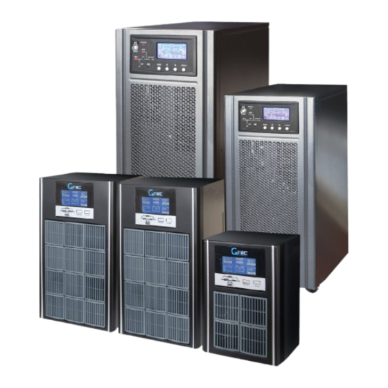
- Page 1 GTEC UPS MODEL: ZY120 1 – 3 kVA SERVICE MANUAL www.gtec-power.eu...
-
Page 2: Table Of Contents
STEPS TO OPEN THE CASE ......................4 INTRODUCTION .......................... 5 2. PRINCIPLE OF OPERATION ......................6 2.1. INTRODUCTION ........................6 2.2 Main power circuit ........................ 14 3. TROUBLE SHOOTING ......................... 21 3.1 Check the broken components ..................23 ZY120 1-3kVA Service manual EN rev.00.docx... -
Page 3: Important Safety Instructions
Before turn on ups, please check that whether the cable and the polarity of the batteries are correct. Important Tips: When need to replace board, please turn off ups, disconnect the mains switch and battery switch (built-in battery, please unplug at least one battery cable), wait for 10 minutes. ZY120 1-3kVA Service manual EN rev.00.docx... -
Page 4: Steps To Open The Case
STEPS TO OPEN THE CASE PLEASE FOLLOW THE STEPS TO OPEN THE CASE ZY120 1-3kVA Service manual EN rev.00.docx... -
Page 5: Introduction
4. Trouble shooting: This part describes the possible failure conditions and procedures to repair it. Before starting to serve this UPS, be sure to read this manual carefully for a correct and safe operation. ZY120 1-3kVA Service manual EN rev.00.docx... -
Page 6: Principle Of Operation
Basically, this ON-LINE UPS system utilizes high frequency PWM techniques to achieve high efficient performance. This UPS can feed a clean, regulated sine- wave output at any load under full load. The sub-systems are described as below: ZY120 1-3kVA Service manual EN rev.00.docx... - Page 7 DR4_J2 DR4_J21 I/P_N DR4_J1 O/P_N DR4_J18 DR4_J19 2 3 4 6 DR4_J10 BAT+ BAT+ BAT- BAT- Internal battery External battery PW4_J5 terminal 1 2 3 4 6 PW1_J3 PW1_J2 PCB_PS1202_PW1 PW1_J1 PW1_J4 (a) 1KVA ZY120 1-3kVA Service manual EN rev.00.docx...
- Page 8 +12V OUTPUT_L PS1103_DR5 fault OUTPUT_N DR5_J5 BAT+ DR5_J23 Internal battery DR5_J6 BAT- 2 3 4 6 DR5_J22 DR5_J10 External battery terminal PW4_J5 1 2 3 4 6 PW4_J3 PW4_J2 PS1103_PW4 PW4_J1 PW4_J4 (b) 2KVA ZY120 1-3kVA Service manual EN rev.00.docx...
- Page 9 OUTPUT_N DR6_J2 BAT+ DR6_J1 DR6_J8 BAT- 2 3 4 6 DR6_J7 DR6_J19 External battery terminal PW4_J5 1 2 3 4 6 PW4_J3 PW4_J2 PS1103_PW4 PW4_J1 PW4_J4 (c) 3KVA Fig. 1: wiring diagram 1-3KVA ZY120 1-3kVA Service manual EN rev.00.docx...
- Page 10 Network surge protection 8A charger board (a) 1kVA ZY120 1-3kVA Service manual EN rev.00.docx...
- Page 11 DSP board Power board EPO board 1A Charger IGBT dirver Netword surge protection 8A charger EMI board (b) 2kVA ZY120 1-3kVA Service manual EN rev.00.docx...
- Page 12 DSP board Power board RS232/EPO board 1A charger IGBT dirver Network surge protection 8A charger EMI board (c) 3kVA Fig. 2: Locations of Assemblies ZY120 1-3kVA Service manual EN rev.00.docx...
- Page 13 RELAY INVERTER INPUT OUTPUT FILTER/EMC FILTER/EMC AC/DC DC/AC RELAY CHARGER DC/DC BATTERY Fig. 3: 1-3KVA series block diagram ZY120 1-3kVA Service manual EN rev.00.docx...
-
Page 14: Main Power Circuit
PFC inductor CT& PFC inductor AC input EMI/RFI&TVSS current Input To DSP board voltage DSP(28035) To DSP board board voltage 3845 2.5V BAT+ IGBT drivers OUTPUT BAT- Fig. 4: Functional Diagram of Main Circuit ZY120 1-3kVA Service manual EN rev.00.docx... - Page 15 If charger is failure, or overcharged, UPS will shutdown charger to protect batteries from damage. BAT+ AC input 3845 2.5V Fig. 5: charger circuit ZY120 1-3kVA Service manual EN rev.00.docx...
-
Page 16: Dc Power Supply
PWM IC(3845)’s Vcc is over 8V. To have proper operation of PWM IC’s Vcc, its input power is controlled by the switch as indicated in fig.6. Power supply circuit is located on power board. BAT+ +12V 3845 Power BAT- Fig. 6: DC power supply ZY120 1-3kVA Service manual EN rev.00.docx... -
Page 17: Input Power Factor Correction
When the input AC power cord is plugged in, the AC relay is activated and the AC power goes through noise filter to the charger and to the line detector. Both DC buses present voltages at about 1.4 times of input RMS voltage. When the ZY120 1-3kVA Service manual EN rev.00.docx... - Page 18 DC buses for inverter. When the utility fails, the ± 390Vdc DC sources are caught up to supply the power needed by the inverter immediately. BAT+ BUS+ DSP PWM BAT- signal BUS- Fig. 9: DC discharge circuit ZY120 1-3kVA Service manual EN rev.00.docx...
- Page 19 20 seconds, The buzzer becomes silent and all the LEDs extinguish. When the utility is coming, the UPS will start up automatically. In case of the battery voltage is high voltage, the UPS ZY120 1-3kVA Service manual EN rev.00.docx...
-
Page 20: Front Panel
Inverter LED indicates inverter is working. Bypass LED flashes and others are dark, indicates UPS is not working and switch power supply is on. LCD includes information about input, output, battery, fault, warn, working mode, load. Please refer to user manual to get detailed information. ZY120 1-3kVA Service manual EN rev.00.docx... -
Page 21: Trouble Shooting
Warn: Bypass Load is on bypass and Remove some loads and restart UPS again. When UPS overload timeout overload. Overload time is working normally, turn on loads one by one. longer than overload capacity ZY120 1-3kVA Service manual EN rev.00.docx... - Page 22 Fault: Charger There charger Please contact with distributer or service center fault output. Warn: input over Abnormal large current Please contact with distributer or service center current enter in rectifier. ZY120 1-3kVA Service manual EN rev.00.docx...
-
Page 23: Check The Broken Components
0.5V, it’s ok. If it’s shorted or opened, it’s broken. Q4,Q5,Q6,Q7 Check every two pins, if they are shorted, it’s broken. Q11,Q12,Q13,Q14 Check the resistor value, if in the range of +-5%, it’s OK MOS drivers resistor R11-R14(10Ω) ZY120 1-3kVA Service manual EN rev.00.docx... - Page 24 R169(10Ω) R146(20Ω) R60(20Ω) Diode D32,D31 Using the diode measure function of multi-meter to measure the diode, if the voltage is near 0.7V, it’s ok. If Diode shorted or opened, it’s broken. D25,D26,D27 Diode D25,D26,D27 ZY120 1-3kVA Service manual EN rev.00.docx...
- Page 25 Using diode measure function of multi-meter to measure the voltage between pin1 and pin2, pin1 to pin3, pin2 to pin4, pin3 to pin4, if the voltage is near 0.7V, it’s OK. If shorted or opened, it’s broken. ZY120 1-3kVA Service manual EN rev.00.docx...
- Page 26 CAUTION: DO NOT supply UPS with the mains unless you are sure that you have replaced all defective components ZY120 1-3kVA Service manual EN rev.00.docx...
Need help?
Do you have a question about the ZY120 and is the answer not in the manual?
Questions and answers