Table of Contents
Advertisement
Quick Links
Advertisement
Table of Contents

Related Manuals for Gtec MUST400


Summary of Contents for Gtec MUST400
- Page 1 Preliminary Version Modular UPS MUST400 USER Manual...
-
Page 3: Safety Precautions
Preliminary Version Safety Precautions This manual is about installation and operation of MUST400 modular UPS (Hereinafter referred as UPS). Please carefully read this manual prior to installation. The UPS must be debugged and maintained by an engineer commissioned by the manufacturer or the agent. -
Page 5: Table Of Contents
Contents Chapter 1 Installation..........................4 1.1 Introduction ..........................4 1.2 Initial Checking..........................4 1.3 Positioning ..........................5 1.3.1 Distribution Room ......................5 1.3.2 Battery Room........................5 1.3.3 Storing ..........................5 1.4 Disassembly, Initial Checking and Positioning ................5 1.4.1 System Packaging: ......................5 1.4.2 Module Packaging: ...................... - Page 6 2.2.3 Auto-Restart Mode......................25 2.2.4 Bypass Mode ......................... 25 2.2.5 Maintenance Mode ......................25 2.2.6 ECO Mode ........................26 2.2.7 Frequency Converters Mode ..................26 2.3 Battery Management......................... 26 2.3.1 Normal Function ......................26 2.3.2 Advanced Functions (Battery Self-checking and Maintenance)........26 2.4 Battery Protection........................
- Page 7 7.3 Mechanical Characteristics ....................... 47 7.4 Electrical Characteristics (Input Rectifier) ................. 48 7.5 Electrical Characteristics (Intermediate DC Link)..............48 7.6 Electrical Characteristics (Inverter Output)................49 7.7 Electrical Characteristics(Bypass Mains Input) ................. 50 7.8 Efficiency........................... 50 Appendix A Guidebook to Ordering and Selection of PM System . Errore. Il segnalibro non è definito.
-
Page 8: Chapter 1 Installation
Chapter 1 Installation Chapter 1 Installation This chapter introduces the installation of RM series UPS (hereby referred to as UPS), including initial checking, sitting, positioning, cabling and installation drawings. 1.1 Introduction This chapter introduces the relevant requirements for positioning and cabling of the UPS. As each site has its requirements, this chapter provides step-by-step installation instructions, which acts as a guide to the general procedures and practices that should be observed by the installing engineer. -
Page 9: Positioning
Chapter 1 Installation 1.3 Positioning 1.3.1 Distribution Room The UPS is designed for indoor installation, which shall be located in a clean environment with adequate ventilation to keep the environmental temperature within the required specification. The UPS uses forced convection cooling by internal fans. Cooling air enters the module through ventilation grills located at the front part of the cabinet and exhausted through grills located in the rear part of the cabinet. - Page 10 Chapter 1 Installation Fig 1-1 Open method Firstly, open the top plate of the steel-edged wooden case with slotted awl and plier, followed by sideboards. Be careful not to scratch the product. See fig 1-2. Fig 1-2 Disassemble the case Take out the foam after disassembling the sideboards of the case as shown in fig 1-3.
-
Page 11: Module Packaging
Chapter 1 Installation Fig 1-3 Complete the disassembly Tip: Dismantle the bolt that connects the cabinet and wooden pallet after disassembly, then lift the cabinet to installation position. The dismantlement should be careful so as not to scratch the body. Verify the product label and confirm the correctness of the equipment. - Page 12 Chapter 1 Installation Foamed package Carton Fig 1-5 Open the carton Open the foamed cover, the equipment with plastic package can be see as shown in fig 1-6: Top cover of foamed package Foamed package Carton Equipment Fig 1-6 Open the foamed cover At last, take out the equipment with plastic package, and dismantle the packaging materials.
-
Page 13: Ups Composition
Chapter 1 Installation Air sufficient enough to dispel heat produced by UPS Against ambient corrosive gases Against excessive humidity and heat sources Against dust With the current fire prevention requirements The operating environment temperature is within 20°C~25°C. The batteries are at maximum efficiency in this temperature range (for information about the battery storage and transportation as well as the environment, please refer to table 6-2). -
Page 14: Operation Space
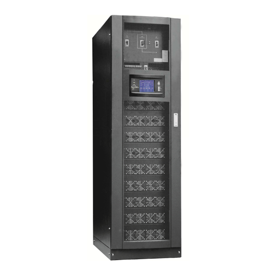
Chapter 1 Installation 开关单元 Switch unit 配电单元 Distribution unit 旁路模块 Bypass module 功率模块 Power module 1.6m cabinet (front view) 1.6m cabinet (back view) Fig 1-7 UPS Composition Diagram Table 1-1 UPS Configuration Table Involved part name Quantity (Piece) Note Switch PDU Standard configuration Cabinet Monitoring + bypass... -
Page 15: Cable Entry
Chapter 1 Installation Each module shall be installed from bottom to top, the default setting of the system is module No. 1, 2, 3, 4, 5, 6, 7, 8, 9, and 10. Insert the module into installation position, and push in the cabinet. The wiring terminals in between shall be tight, and excessive force shall be prevented against the damage to inserted pins of the terminals. -
Page 16: Protective Devices
Chapter 1 Installation 1.5 Protective Devices For safety concerns, it is recommended to install external circuit breakers or other protective devices for the input AC supply of the UPS system. This section provides generic practical information for qualified installation engineers. The installation engineers should have the knowledge of the regulatory wiring standards, and of the equipment to be installed. -
Page 17: Ups Output
Chapter 1 Installation 1.5.3 UPS Output A main output switch has been installed in UPS, the user shall install the over current protective device on the bypass of each output of the external distribution cabinet. 1.6 Power Cables Design the cables according to the descriptions in this section and local regulatory wiring standards, and the environmental conditions should be taken into consideration. -
Page 18: Control And Communication Cabling
Chapter 1 Installation After the equipment has been finally positioned and secured, connect the power cables as described in the following procedures: Verify that all the external input distribution switches of the UPS are completely opened and the UPS internal maintenance bypass switch is opened. Attach necessary warning signs to these switches to prevent unauthorized operation. -
Page 19: Dry Contact Interface Of Battery And Environmental Temperature Detection
Chapter 1 Installation 1.7.1 Dry Contact Interface of Battery and Environmental Temperature Detection The input dry contact J2 and J3 can detect the temperature of batteries and environment respectively, which can be used in environment monitoring and battery temperature compensation 1. J2 and J3 interfaces diagram are shown in fig 1-13, the description of interface is in table 1-3. -
Page 20: Generator Input Dry Contact
Chapter 1 Installation J4.3 EPO_NO EPO is activated when shorting with J4.2 The EPO is triggered when shorting pin 2 and 3 or opening pin 2 and 1 of J4. If an external emergency stop facility is required, it is connected via the reserved terminals of J4. The external emergency stop facility needs to use shielded cables to connect to the normally open/closed remote stop switch between these two pins. -
Page 21: Battery Warning Output Dry Contact Interface
Chapter 1 Installation Fig 1-16 BCB Port Table 1-6 Description of BCB port Position Name Description J6.1 BCB_DRV BCB actuating signal, provide the actuating signal of +18V, 20mA J6.2 BCB_CONT BCB contact status, connect with the normally open signal of BCB J7.1 Power ground BCB on-line–input (normally open) , BCB is on-line when the signal... -
Page 22: Mains Failure Warning Output Dry Contact Interface
Chapter 1 Installation Fig 1-18 Integrated warning dry contact interface diagram Table 1-8 Integrated warning dry contact interface description Position Name Purpose J9.1 ALARM_NC Integrated warning relay (normally closed) will be open during warning J9.2 ALARM_NO Integrated warning relay (normally open) will be closed during warning J9.3 Centre of integrated warning relay 1.7.7 Mains Failure Warning Output Dry Contact Interface... -
Page 23: Lbs (Load Bus Synchronizer) Port
Chapter 1 Installation 1.7.9 LBS (Load Bus Synchronizer) Port The dual bus system (DBS) consists of two independent UPS rack module systems, as shown in fig 1-20. The dual bus system is configured for high availability and is suitable for powering the load with dual inputs. - Page 24 Chapter 1 Installation Fig 1-21 Installation Diagram 顶视图 Top view 2m cabinet front view 1.6 m cabinet (front view) Fig 1-22 UPS front view (Unit: mm)
- Page 25 Chapter 1 Installation 2m cabinet Ѫ 1.6m cabinet Fig 1-23 UPS back view...
- Page 26 Chapter 1 Installation A处放大 Amplification of A Fig 1-24 UPS front view Ѫ...
-
Page 27: Chapter 2 Operations
Chapter 2 Operations Chapter 2 Operations This chapter introduces the basic knowledge of UPS operations, including working principle, operation mode, battery management and protection. Warning: Hazardous mains voltage and/or battery voltage present(s)behind the protective cover The components that can only be accessed by opening the protective cover with tools can not be operated by user. -
Page 28: Bypass Module
Chapter 2 Operations Fig 2-1 System principle framework 2.1.2 Bypass Module The circuit blocks labeled “bypass module” in fig 2-1 contain electronically controlled switching circuits that enable the critical load to be connected to either the inverter output or to a bypass power source via the static bypass line. -
Page 29: Normal Mode
Chapter 2 Operations Battery mode Auto-Restart mode Bypass mode Maintenance mode (manual bypass) ECO mode Frequency converters mode 2.2.1 Normal Mode The UPS inverter power modules continuously supply the critical AC load. The rectifier/charger derives power from the AC mains input source and supplies DC power to the inverter while simultaneously FLOAT or BOOST charging its associated backup battery. -
Page 30: Eco Mode
Chapter 2 Operations 2.2.6 ECO Mode If economical (ECO) mode is selected, the double-conversion UPS will stop to work so as to save energy. During the operation of ECO mode, the load power will be supplied by bypass preferentially. When bypass power is within the range of normal frequency and voltage, load power will be supplied by bypass, or the system will transfer to inverter output, followed by load power interruption which extends within 3/4 of the utility period. -
Page 31: Battery Protection
Chapter 2 Operations 2.4 Battery Protection The following functions should be fitted by commissioning engineers with specified software. Battery Low Pre-warning The battery under voltage pre-warning occurs before the end of discharge. After this pre-warning, the battery should have the capacity for 3 remaining minutes discharging with full load. The time is user configured from 3 to 60 minutes. -
Page 32: Chapter 3 Operating Steps
Chapter 3 Operating Instructions Chapter 3 Operating Steps This chapter describes UPS operation instructions in detail. All functional keys and LED display involved in operation instructions please refer to chapter 4. During operation, the buzzer alarm may occur at any time. Select “mute” on LCD to muffle the audible alarm. -
Page 33: Normal Module Start
Chapter 3 Operation Instructions 3.2.1 Normal Module Start This procedure must be followed when turning on the UPS from a fully powered down condition. The operating procedures are as follows: Warning This procedure results in mains voltage being applied to the UPS output terminals. If any load equipment is connected to the UPS output terminals please check with the load user that it is safe to apply power. - Page 34 Chapter 3 Operating Instructions Press the red start-up button of battery under the rectifier input circuit breaker for 3 seconds (see fig 3-2). The LCD starts up at this time. The green battery indicator flashes. The rectifier enters normal operation states and after about 30s, the battery indicator goes steady green. The inverter starts up automatically, the green inverter indicator flashes.
- Page 35 Chapter 3 Operation Instructions Battery startup button 电池启动按钮 Ҫ Fig 3-2 Position diagram of battery startup button...
-
Page 36: Procedure For Switching Between Operation Modes
Chapter 3 Operating Instructions 3.3 Procedure for Switching between Operation Modes 3.3.1 Procedure for Switching the UPS into Battery mode from Normal Mode Open input switch to cut off the mains, UPS enters the battery mode. If UPS should be switched to normal mode, wait for a few seconds before closing input switch, so as to supply the mains again. -
Page 37: Procedure For Completely Powering Down A Ups
Chapter 3 Operation Instructions The load power is supplied by bypass. In the meantime, the rectifier starts up, rectifier indicator goes green 30s later, at this time, the inverter will start up automatically, and transfer to inverter mode 1 min later automatically. -
Page 38: Chapter 4 Operator Control And Display Panel
Chapter 4 Operator Control and Display Panel Chapter 4 Operator Control and Display Panel This chapter introduces the functions and operation instructions of the parts on UPS operator control and display panel in detail, and provides LCD display information, including LCD display types, detailed menu information, prompt window information and UPS alarm list. -
Page 39: Led Indicator
Chapter 4 Operator Control and Display Panel 4.1.1 LED Indicator The LEDs shown on the mini current path represent the various UPS power paths and show the current UPS operating status. The status description of indicators is shown in table 4-2. Table 4-2 Status description of indicator Indicator State... -
Page 40: Functional Keys
Chapter 4 Operator Control and Display Panel 4.1.3 Functional Keys There are 4 functional keys on operator control and display panel, which are used together with LCD. The functions description is shown in table 4-4. Table 4-4 Functions of functional keys Functional key Functions To cut off the load power to shut down the rectifier, inverter, static... - Page 41 Chapter 4 Operator Control and Display Panel Icon Description Main input parameter History file, system information Function setting (display calibration, password setting, time setting, date format, communication protocol and language setting), system setting (used by product maintainers) Battery data, battery parameter setting (used by service staff) Test (battery self-test, battery maintenance) Functional keys used by service staff (fault clearing, history file clearing, noise clearing, manual switch of bypass),...
- Page 42 Chapter 4 Operator Control and Display Panel 5 modules on-line RM33-120/20 5模块在线 12:00 相电压(V) 相电流(A) I phase V phase 主路输入 Main input 18.3 219.5 18.3 219.5 18.3 219.5 功率因数 频率(Hz) Power factor Frequency 0.99 50.01 50.01 0.99 0.99 50.01 Fig 4-3 Select data Or select and confirm a module, as shown in fig 4-4, the LCD will display the operating status of this module:...
-
Page 43: Detailed Description Of Menu Items
Chapter 4 Operator Control and Display Panel Select in the operating status of a module to view the main output data of this module. Select , in the operating status of a module to view the load data of this module. Select in the operating status of a module to view the maintenance code and module software code of this module. - Page 44 Chapter 4 Operator Control and Display Panel Menu name Menu item Meaning Load (%) Load (The percentage of the UPS rating load) Environmental Environmental Temp Temp Battery Battery bus voltage voltage(V) Battery current Battery bus current Battery Temp ℃ Battery Temp(℃ ) Remaining Time Remaining battery backup time (Min.)
-
Page 45: Alarm List
Chapter 4 Operator Control and Display Panel Menu name Menu item Meaning software version Rectified Provide rectified software version software version Inverted Provide inverted software version information software version Serial No. The serial no set when delivery from the factory Rated Network setting of system operating information... - Page 46 Chapter 4 Operator Control and Display Panel Alarm Explanation Battery manual Battery fault during system self-check check failure Battery maintenance The system is in battery maintenance status Battery maintenance Battery maintenance status completes success Battery maintenance Battery maintenance process is not normal failure Stop testing Battery self-check or battery maintenance status stops...
-
Page 47: Chapter 5 Installation Of Parallel Operation System
Chapter 5 Maintenance Chapter 5 Installation of Parallel Operation System The parallel operation system is installed as required by the installation procedures of the single system and this chapter. The single devices are put parallel and connected as shown in fig. 5-1, and the difference between the lengths of the output cables of the single devices is not more than 10m. - Page 48 Chapter 5 Maintenance Fig.5-2 parallel cables 庀 ґ...
-
Page 49: Chapter 6 Maintenance
Chapter 5 Maintenance Chapter 6 Maintenance This chapter introduces UPS maintenance, including the maintenance instructions of power module, monitoring bypass module and the change method of dust filter. 6.1 Instruction to Power, Bypass, and Output Power Distribution Module 6.1.1 Precautions Only maintaining engineers can maintain the power module and monitoring bypass module. -
Page 50: Replacing Dust Screen (Optional)
Chapter 5 Maintenance Take off the fixing bolt at the two sides of front board of bypass module, extract the front cable assembly of the module and extract the module from the cabinet. After maintaining the module, insert the module into the cabinet, tighten the screw at the two sides, and connect the front cable assembly of manufacturer’s module. -
Page 51: Chapter 7 Product Specification
Appendix 2 Toxic or Hazardous Materials or Elements Identification Table Chapter 7 Product Specification This chapter provides UPS product specification. 7.1 Applicable Standards The UPS has been designed to conform to the following European and international standards: Table 7-1 Compliance with European and International Standards Item Normative reference General safety requirements for UPS... -
Page 52: Electrical Characteristics (Input Rectifier)
Chapter 5 Maintenance Module type Unit RM20 Mechanical Dimension, W×D×H 440×590×134 Weight Color Black 7.4 Electrical Characteristics (Input Rectifier) Table 7-4 Rectifier AC input (mains) Items Unit Parameter Rated AC Input 380/400/415(three-phase and sharing neutral with the Voltage bypass input) -40%~+25% (-10%+25% full load) Input voltage range Vac 50/60Hz (range: 40Hz~70Hz) -
Page 53: Electrical Characteristics (Inverter Output)
Appendix 2 Toxic or Hazardous Materials or Elements Identification Table 7.6 Electrical Characteristics (Inverter Output) Table 7-6 Inverter Output (to important load) 20~ ~ ~ ~ 200 Rated capacity(kVA) Unit 380/400/415(three-phase four-wire and sharing neutral with the Rated AC voltage bypass) Freqency 50/60Hz... -
Page 54: Electrical Characteristics(Bypass Mains Input)
Chapter 5 Maintenance 7.7 Electrical Characteristics(Bypass Mains Input) Table 7-7 Bypass Mains Input Rated Unit 120kVA 200kVA capacity(kVA) Rated AC 380/400/415 Three-phase four-wire, sharing neutral with the rectifier Voltage input and providing neutral reference for the output 182@380V 302@380V Rated current 174@400V 288@400V 166@415V...
Need help?
Do you have a question about the MUST400 and is the answer not in the manual?
Questions and answers