Gtec ZP120N User Manual
Online double conversion ups single and three phases input
Hide thumbs
Also See for ZP120N:
- User manual (126 pages) ,
- Service manual (58 pages) ,
- Service manual (50 pages)
Table of Contents
Advertisement
USER MANUAL
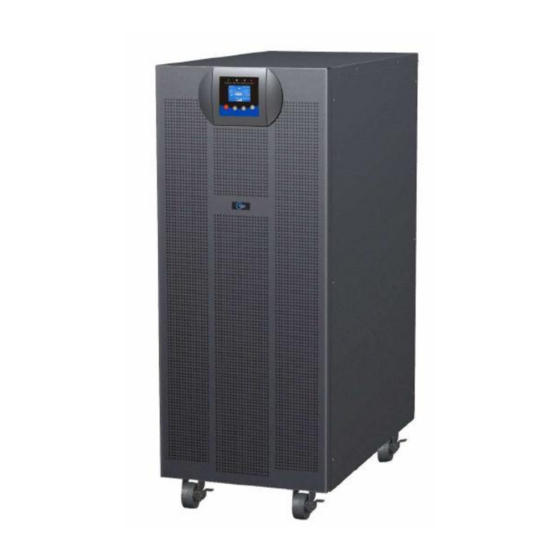
ZP120N 10-20kVA 3phases/1phase
Uninterruptible power supply
CONTENT:
1. Safety........................................................................................................... 1
1.1 Installation .............................................................................................. 1
1.2 Operation ............................................................................................... 2
1.3 Maintenance, Servicing and Faults........................................................ 3
1.4 Transport ................................................................................................ 4
1.5 Storage................................................................................................... 4
1.6 Standards ............................................................................................... 5
2. Description of Commonly Used Symbols................................................ 6
3. Introduction................................................................................................. 7
3.1 System and Model Description .............................................................. 7
3.2 Product Specification and Performance............................................... 10
4. Installation................................................................................................. 13
4.1 Unpacking and Inspection.................................................................... 13
Installation .................................................................................................. 16
5. Operation................................................................................................... 23
5.1 Display Panel ....................................................................................... 23
5.2 Operating Mode ................................................................................... 27
5.3 Turning On and Turning Off UPS ......................................................... 29
5.4 LCD Operation ..................................................................................... 31
6. Special function........................................................................................ 40
6.1 HE Function ......................................................................................... 40
Advertisement
Table of Contents
Troubleshooting

Related Manuals for Gtec ZP120N


Summary of Contents for Gtec ZP120N
-
Page 1: Table Of Contents
1.3 Maintenance, Servicing and Faults............3 1.4 Transport ....................4 1.5 Storage....................4 1.6 Standards ....................5 ZP120N 10-20kVA 3phases/1phase 2. Description of Commonly Used Symbols..........6 3. Introduction....................7 3.1 System and Model Description .............. 7 3.2 Product Specification and Performance..........10 4. -
Page 2: Safety
6.2 Converter Function ................40 1. Safety 6.3 Parallel Function .................. 41 Please read carefully the following user manual and the safety 6.4 tower 3/1 10K Optional Design of Charger Current ......47 instructions before installing the unit or using the unit! 6.5 Backfeed Protection ................ -
Page 3: Installation
1.3 Maintenance, servicing and faults An appropriate disconnect device as short-circuit backup protection should be provided in the building wiring ★ The UPS operates with hazardous voltages. Repairs should be installation. carried out only by qualified maintenance personnel. For three-phase equipment connection to an IT power system, ★... -
Page 4: Transport
1.6 Standards ★ Do not attempt to dispose of batteries by burning them. It could cause explosion. * Safety Do not open or destroy batteries. Effluent electrolyte can cause ★ IEC/EN 62040-1 injury to the skin and eyes. It may be toxic. * EMI Please replace the fuse only by a fuse of the sa me type and of... -
Page 5: Description Of Commonly Used Symbols
2. Description of Commonly Used Symbols 3. Introduction Some or all of the following symbols may be used in this manual. It is 3.1 System and model description advisable to familiarize yourself with them and understand their This Online Series is an uninterruptible power supply incorporating meaning: double-conversion technology. - Page 6 High output power factor (0.9), to adapt more type load. Intelligent Battery Management technology that uses advanced battery management to increase battery service life, optimize recharge time. Selectable High Efficiency mode (ECO mode) or CVCF mode operation. Combo input (single phase or three phase) auto detection Back-feed protection Start-on-battery capability for powering up the UPS even if utility power is not available.
-
Page 7: Product Specification And Performance
Voltage 200VAC/208VAC/220VAC/230VAC/ 240VAC* Parallel Port Intelligent Slot Output 45A/48.1A/45.5A/4 90A/96.2A/90.9A/8 45A/48.1A/45.5A/4 (Optional) Current 3.5A/41.7A 7.0A/83.3A 3.5A/41.7A 、 EPO、 RS232 USB Dimension 350x650x890 260*550*708 (WxDxH) mm Net Weight (kg) External Battery 2) Electrical Performance AS400 IEC Connector Input Maintenance and Output Switch Cover Model Voltage... -
Page 8: Installation
4. Installation 3) Operating Environment Temperature Humidity Altitude Storage temperature The system may be installed and wired only by qualified 0°C-45°C <95% <1000m -15°C-50°C electricians in accordance with applicable safety regulations! Note: if the UPS is installed or used in a place where the altitude is 4.1 Unpacking and Inspection above than 1000m, the output power must be derated in use, please refer to the following:... - Page 9 Remove the packaging following the sequence illustrated in Fig. 4-1 to Fig. 4-4. (only for tower 3/1 10k-20k) Tools kit Lifter Phillips screwdriver Scissors Wrench Fig. 4-3 Unpacking-step3 Fig. 4-4 Unpacking-step4 The shipping materials are recyclable. After unpacking, save them for later use or dispose of them appropriately. 2) Inspect the appearance of the UPS to see if there is any damage during transportation.
-
Page 10: Input And Output Power Cords And Protective Earth Ground
4.2 Input and Output Power Cords and Protective For safety, please cut off the mains power switch before installation. Earth Ground Installation Open the terminal block cover located on the rear panel of the UPS, please refer to the appearance diagram. 1. - Page 11 To connect the load with the UPS, please turn off all the loads first, then perform the connection and finally turn on the loads one by one. No matter the UPS is connected to the utility power or not, the output of the UPS may have electricity.
-
Page 12: Operating Procedure For Connecting With The External Battery
External Battery Cabinet Positive Output L,N, Pole(+),Neutral pole,Negative Min.conductor cross section[mm pole(-), Max.conductor cross section[mm Min.conductor cross section[mm External Battery Cabinet Positive Max.conductor cross section[mm Pole(+),Neutral pole,Negative Line input Backfeed protection device A 4-pole disconnection device with 100A/250VAC, less than 15s break pole(-), time and min. -
Page 13: Operation
5. Operation 5.1 Display Panel The UPS has a four-button graphical LCD with dual color backlight. Standard back-light is used to light up the display with white text and a blue background. When the UPS has a critical alarm, the backlight changes the text to dark amber and the background to red. - Page 14 Normal LED Battery LED Bypass LED Fault LED UPS state The Button Function Illustration (Green) (Yellow) (Yellow) (Red) When the unit is no power and has connected Bypass mode Power on with battery, press this button for >100ms&<1s ↑ ★ to power on with no output Bypass mode...
-
Page 15: Operating Mode
measurements, identification, and settings through the front panel display. 5.2 Operating Mode After powering on, the LCD will display the “WELCOME” logo for several The different graphic symbol could be displayed corresponding to current seconds and then enter to the default page which shows the UPS status operating mode or status. -
Page 16: Turning On And Turning Off Ups
High Efficiency Mode: Fault: After the UPS is turned on, the power used by When the fault occurs, it illustrates that some the load is supplied from the utility power via fatal problems happened, the UPS would internal filter while the utility power is in directly cut off the output or transfer to normal range, so the high efficiency could be bypass, and keep alarming. -
Page 17: Lcd Operation
2) When completing the above action, UPS output voltage is still 5.3.1 Turning On UPS With Utility present. In order to cut off the UPS output, simply cut off the utility Check that power supply connection is correct. Check the breaker power supply. - Page 18 5.4.2 The UPS Status Menu By pressing on the menu of “UPS status”, the display would enter the next UPS status menu tree. The content of UPS status menu tree is same as the default UPS status summary menu. By pressing >1s, the display would return the last main menu tree.
- Page 19 Fig. 5-16 Measurement menu tree 5.4.5 The Control Menu By pressing on the menu of “Control”, the display would enter the next control menu tree. Start Battery Test: is one command to control the UPS to do the battery test. Fig.
- Page 20 Restore factory settings: all the settings would be recover to 5.4.6 The Identification Menu default factory settings. It could only be done in Bypass mode. By press on the menu of “Identification”, the display would enter the next identification menu tree. The identification information includes UPS serial number, firmware serial number, model type, would be shown here.
- Page 21 Example: set rated output voltage value function loss, even directly damage the load, battery or UPS. The most of settings could only be done while UPS is in Bypass mode. Fig. 5-20 Set rated output voltage value Fig. 5-19 Setting menu tree *:Password is USER when enabled...
-
Page 22: Special Function
6. Special Function The great virtue is the output frequency is fixed, which is required by some very sensitive loads. The series UPS has some special functions, which could satisfy some But the load should be derated to 60% when running in converter special application of user. - Page 23 Strictly follow the chapter of 4, the wiring requirement of single UPS to perform the wiring of each UPS. Connect the output wires of each UPS to an output breaker panel. Disconnect the Jumper on JP1 and JP2 of the terminal block first, and connect each output breaker to a main output breaker and then to the loads.
- Page 24 4) For tower 3/1 10k-20k ,Set the main maintenance switch or static 10) Do not switch on the output breaker of each UPS, switch on the input breaker of the each UPS, the UPS should work in bypass with switch from “UPS” to “BPS”, For tower 3/1 10K-31C model, turn the output, observe their display to check if there are any warning or maintenance switch in the “ON”...
-
Page 25: Tower 3/1 10K Optional Design Of Charger Current
own maintenance switch in the “ON” position, and turn the own 6.4 Tower 3/1 10K Optional Design of Charger output switch in the “OFF” position. Current 3) For tower 3/1 10k-20k, Set the main maintenance switch or static 6.4.1 Our charger output current has two optional levels switch from “UPS”... -
Page 26: Backfeed Protection
6.5 Backfeed Protection To support protection against UPS backfeeding a new logic is integrated into tower 3/1 10k-20k model. But in tower 3/1 10K-31C model,there’s no this function. Using backfeed protection On customers side an additional external isolation device (magnetic contactor, MC or minimum voltage tripping device) must be provided as shown in Fig. -
Page 27: Trouble Shooting
7. Trouble Shooting Operation If the UPS system does not operate correctly, first check the operating If bypass thyristor is short (short circuit) and UPS runs in double information on the LCD display. conversion mode (online) the following steps follow: Please attempt to solve the problem using the table below. -
Page 28: Trouble Shooting According To Fault Indication
Inside temperature of Check the ventilation of UPS and 7.2 Trouble Shooting According To Fault Indication Heatsink Over UPS is too high the ambient temperature. Temperature Alarm code:86 Problem Displayed Possible cause Remedy The parallel cable is Check the parallel cable. Para Cable Male Loss Inv Overload Fault Overload... -
Page 29: Trouble Shooting In Else Cases
Inv Under Voltage UPS internal fault Consult dealer. Emergency supply Batteries not fully Charge the batteries for at least 12 Alarm code:33 period shorter than charged / batteries hours and then check capacity. Inv Softstart Fail UPS internal fault Consult dealer. nominal value defect Alarm code:34... -
Page 30: Battery Maintenance, Replacement And Disposal
8. Battery Maintenance, Replacement and 8.2 Replacement and Disposal of Batteries Disposal 1) Before disposing of batteries, remove conductive jewelry such as necklace, wrist watches and rings. 8.1 Maintenance 2) If it is necessary to replace any connection cables, please ■... - Page 31 Easy for Battery Replacement (for tower 3/1 10k-20K model) 3) Remove the battery pack from the cabinet. See Fig. 8-3. Open the front panel and request service engineer to replace batteries. Steps: 1) Remove the front panel and disconnect the connector on the LCD display board.
-
Page 32: Communication Port
9. Communication Port Pin # Description Pin # Description UPS Fail Output Bypass Output 9.1 RS232&USB Interface Summary Alarm Output Battery Low Output RS232&USB interface is for the monitoring software and firmware Input UPS ON Output update. There is only one option can work in the same time and same Remote Shutdown Input Line Loss... -
Page 33: Software
10. Software Free Software Download – WinPower WinPower is a UPS monitoring software, which provides user-friendly interface to monitor and control UPS. This unique software provides safely auto shutdown for multi-computer systems while power failure. With this software, users can monitor and control any UPS on the same LAN, which communicated with local computer through RS232 or USB protocol, no matter how far from the UPSs.
Need help?
Do you have a question about the ZP120N and is the answer not in the manual?
Questions and answers