FUTABA CGY750 Instruction Manual
Flybarless control gyro for model helicopter
Hide thumbs
Also See for CGY750:
- Instruction manual (123 pages) ,
- Instruction manual (28 pages) ,
- Instruction manual (31 pages)
Advertisement
Quick Links
Advertisement

Subscribe to Our Youtube Channel
Related Manuals for FUTABA CGY750


Summary of Contents for FUTABA CGY750
- Page 1 NSTRUCTION ANUAL 1M23N24902...
- Page 2 ABLE OF ONTENTS...
- Page 3 : Instructions for gyro functions Gyro : Instructions for governor function Governor Technical updates and additional programming examples can be found at: www.futaba-rc.com/faq RECAUTIONS DANGER - Procedures which may lead to dangerous conditions and cause death/serious injury if not carried out properly.
- Page 4 flight. Always exit programming mode before at- tempting to fly the model. Only use the CGY750 with a 2.4GHz system such as the Futaba FASST™ system, or a PCM system. Use with an FM system is strongly dis- couraged since interference can cause serious operational problems.
- Page 5 The servo type parameters within the CGY750 must match the type of servo you are using. In- correct setting may damage the CGY750 or the servos, possibly resulting in a loss of control dur- ing flight.
- Page 6 Do not drop the CGY750 sensor onto a hard surface or subject the CGY750 sensor to a strong shock as this may damage the sensor.
- Page 7 RECAUTIONS transmitter, always set the throttle servo maxi- mum operating point to less than the point at which the governor is activated. If this is not done the governor may activate while in condition hold. While preparing for flight or starting the engine always ensure the throttle remains below the gov- ernor activation point and do not select any flight modes that may activate the governor.
- Page 8 ARRANTY & EPAIR ERVICE (IN U.S.A.) www.futaba-rc.com or www.hobbyservices.com Fax (217)-398-7721, Tel (217) 398-0007 numbers) Futaba Service Center 3002 N Apollo Drive Suite 1 Champaign, IL 61822...
- Page 9 NTRODUCTION EATURES...
- Page 10 EATURES...
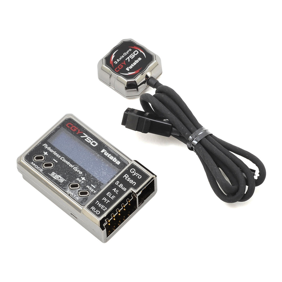
- Page 11 EATURES ONTENTS SET CONTENTS CGY750 Control Amp *Mini Screwdriver *Dust Covers (x3) Gyro Sensor *Mounting Pads (x3) Governor Sensor --- --- X *Sensor Mounting Hardware *Magnet (x2) --- X --- X R6203SB Receiver Extension Cord X: supplied ---: not supplied...
- Page 12 ONTENTS CGY750 Control Box Dust Cover Adjustment Screwdriver Gyro Sensor Mounting Pads R6203SB Receiver...
- Page 13 ONTENTS Revolution Sensor Magnets (2) Sensor Mounting Bracket Extension Cord:...
- Page 14 PECIFICATIONS...
- Page 15 ECOMMENDED ERVOS Futaba S9254 Digital Servo Heli: FUTM0224 (280Hz/1520μS) Futaba BLS254 Brushless Heli Servo: FUTM0524 (280Hz/1520μS) Futaba S9257 EP Heli Digital Servo: FUTM0667 (280Hz/1520μS) Futaba BLS257 EP Brushless Heli Servo: FUTM0527 (280Hz/1520μS) FUTM0226 Futaba BLS251 Brushless Heli Servo: FUTM0521 EPLACEMENT &...
- Page 16 CGY750 ONNECTING THE OLED Display ters and status information. Edit Keys justment screwdriver to press the buttons.
- Page 17 CGY750 ONNECTING THE (1) Gyro Sensor: *Insert the sensor connector until it is firmly locked. (2) Rsen (Revolution sensor): (3) S.Bus: receiver with the supplied extension. (4) AIL Output: (5) ELE Output: (6) PIT Output: (7) TH Output: (7) E2 2nd ELE Output:...
- Page 18 CGY750 ONNECTING THE...
- Page 19 CGY750 ONNECTING THE DANGER It is necessary to remove the pinion gear from the electric motor or disconnect the mo- tor from the ESC before powering the model...
- Page 20 CGY750 ONNECTING THE up for setup or bench testing. Electric motors are extremely powerful and the capable of de- livering the power instantly causing injury to yourself, others, or the surroundings.
- Page 21 Please use the guidelines below and address all is- sues before installing and flying the CGY750. tempt to fly the CGY750 using a wire driven tail rotor system. pulleys, belt, bearings and shafts are in proper working condition.
- Page 22 ECHANICS REPARATIONS crease the performance of the CGY750 gyro and this may also shorten the servo lifespan. Please take the time now to ensure the tail rotor system on your helicopter is working correctly, without fric- tion or binding. mance. All rotating components on the helicop- ter should be balanced to minimize vibrations in flight.
- Page 23 PENING CREEN...
- Page 24 CREEN 1. Axis indication 2. Gyro operation mode 3. Gyro gain 4. on/off switch 7. Setting Menus 5. Yaw rate comp. 6. Battery voltage (b) Aileron gain (c) Elevator gain (d) Gyro only display display mode 1. Axis indicator Gyro 2.
- Page 25 CREEN RUD AVCS Mode RUD NOR Mode Neutral offset at at 100% gain at 100% gain AVCS mode Return servo to center position Read and memorize the current neutral position.
- Page 26 CREEN 3. Gyro gain Gyro 4. Operating condition Governor 5. Yaw rate comp. Governor 6. Battery voltage 7. Setting Menus Governor...
- Page 27 CREEN 1. Maximum RPM Governor 2. Engine runtime Governor...
- Page 28 CREEN 3. OLED display options [default: Saver] 4. Operation mode [default: Gyro+Gov] WARNING If the operating mode has been changed then the CGY750 must be reset by powering down and then powering back up.
- Page 29 CREEN 1. Roll rate maximum display Gyro 1. Elevator rate maximum display Gyro ARNING isplay Governor...
- Page 30 ARNING ISPLAY Gyro WARNING The helicopter must remain perfectly still during the initialization process or a [Sensor- ER] sensor calibration error may occur. WARNING The [Low Batt] warning is displayed if the...
- Page 31 ARNING ISPLAY receiver battery voltage falls below the [BAT/ FS] voltage set within the CGY750 ´ Gover- nor ´ Expert menu. If this condition lasts for more than one second then the Battery Fail Safe function activates and the throttle servo is brought back to idle.
- Page 32 The gyro operation is disabled within sev- eral of the settings menus to help with setup tasks. Always check the operation of the CGY750, verify that the controls are operating the correct direction and ensure the gyros are correcting in the proper direction for all axis...
- Page 33 ETTING ENUS Push MODE +/– key Push DATA Maximum RPM +/– key Engine runtime OLED Setting Home screen Operating mode Maximum Roll Rate Maximum elevator rate (Basic) (Expert) Gyro (RUD) Gyro (AIL) Gyro (ELE) Swash Governor Push MODE +/– key for 1 second...
- Page 34 UDDER ASIC ETTING...
- Page 35 UDDER ASIC ETTING Push MODE +/– key Use the mode [+] / [-] keys to navigate the setting menus. Select the appropriate setting for the tail rotor servo that you are using. Use the data [+] or [-] key to choose from the following servo types: DG 760: BLS251, S9256, S9251 DG 1520: BLS254, BLS257, S9254, S9257...
- Page 36 The CGY750 should compensate by adding clockwise rotation pitch to the tail rotor blades. If the CGY750 compen- sates by adding counter-clockwise rotation pitch to the tail rotor blades, then it will be necessary to reverse the Compensation Direction setting by pressing the [+] or [-] data key.
- Page 37 To obtain the best performance it is recommended to set the limit in the CGY750 the servo arm length to set the mechanical endpoints. After that has been completed use the servo limit parameter to make small adjust- ments that could not be made mechanically.
- Page 38 UDDER ASIC ETTING Selects the flight mode. Always try the “Sports” flight mode first and if you determine that the feel is not aggressive enough or if the pirouette mode. The “Sports” Flight Mode will satisfy most pilots. The flight mode is changed by pushing the data [+] or [–] key.
- Page 39 This parameter controls which direction the CGY750 (roll axis) will compensate when the helicopter rolls. Pick the helicopter up and roll the helicopter to the right. The CGY750 should compensate by adding left cyclic to the swash plate. If the CGY750 compensates in the wrong...
- Page 40 The top line shows the Aileron Gyro Base Gain and the bottom line shows the actual working gain as set within the transmitter. If the Aileron Gain Channel is set to [INH] within the CGY750 [S.Bus]->Basic setting menu, then the remote transmitter gain adjustment is not available and the actual working gain is set by using data [+] or [-] keys within this parameter.
- Page 41 Use the mode [+] / [-] keys to navigate the setting menus. This parameter controls which direction the CGY750 (pitch axis) will compensate when the helicopter pitches forward or backward. Pick the helicopter up and rotate the nose of the helicop- ter downward.
- Page 42 The top line shows the Elevator Gyro Base Gain and the bottom line shows the actual working gain as set within the transmitter. If the elevator Gain Channel is set to [INH] within the CGY750 [S.Bus]->Basic setting menu, then the remote transmitter gain adjustment is not available and the actual working gain is set by using data [+] or [-] keys within this setting menu.
- Page 43 WASH ASIC ETTING Push MODE +/– key Use the mode [+] / [-] keys to navigate the setting menus. (Confirmation screen) ing the Data [+] key once will show the next ing confirmation of the change. If the Data [+] (Set) key is pressed again within one second, the new swash plate type is selected and the “?”...
- Page 44 The available presets are 450-550, The size profiles change many of the options within the CGY750 to tailor the gyro towards a certain helicopter size and the way that it reacts in flight. When using this option the CGY750 will be adjusted to provide a consistent feel for various helicopter sizes.
- Page 45 ASIC ETTING The flight mode presets are used to control the overall feel and aggressiveness of the CGY750 in flight. The adjustment range is 1 through 5. Flight mode 1 is the least aggressive and is intended for beginners, sport, scale and even pilots who are not very aggressive.
- Page 46 This setting is used to set the operational direc- tion for the Aileron CCPM servo. The easiest way to set up the CGY750 is to observe which direction each servo needs to move when the collective stick is moved towards positive col- lective pitch.
- Page 47 This setting is used to set the operational direc- tion for the Pitch CCPM servo. The easiest way to set up the CGY750 is to observe which direc- tion each servo needs to move when the col- lective stick is moved towards positive collective pitch.
- Page 48 CGY750. Use the Data [+] or [-] key to make an adjustment. If any of the functions operate the incorrect di-...
- Page 49 ETTING rection, then reverse the sign of the value. For the servo, neutral and reversing adjustments should be made within the CGY750 and the transmitter functions should be left at the default values. pendent on servo arm length and head geom- etry, so it will be necessary to use a pitch gauge to make adjustments.
- Page 50 ENSOR NSTALLATION axis Gyro Sensor...
- Page 51 ENSOR NSTALLATION Important: The CGY750 gyro sensor must be mounted so that the roll and pitch sensing axis are in alignment with the helicopter. Any misalign- ments over 1/2 of a degree will cause a loss in performance. Please take extra care in this step to ensure the optimum flight performance.
- Page 52 Throughout extensive testing it has been found that the CGY750 gyro sensor performs best when the sensor is mounted rigidly to the airframe. This is mainly...
- Page 53 WASH ERVO NSTALLATION AND ETUP H3-120 H3-140 H3-90 H4-00 ELE2 H4-45 Normal ELE2 FRONT...
- Page 54 WASH ERVO NSTALLATION AND ETUP...
- Page 55 WASH ERVO NSTALLATION AND ETUP...
- Page 56 WASH ERVO NSTALLATION AND ETUP...
- Page 57 WASH ERVO NSTALLATION AND ETUP...
- Page 58 ILERON LEVATOR ETUP Using the T8FG, T12FG, T12Z and 14MZ Re- mote Gain Functions (roll, pitch and yaw) WARNING Verify that the gyro compensates in the cor- rect direction for all three axis before flight. If the compensation direction is incorrect, the model will roll, flip, or pirouette uncontrollably at a very high rate.
- Page 59 ILERON LEVATOR ETUP Setting the CGY750 gains by using endpoints or manual adjustments WARNING Verify that the gyro compensates in the cor- rect direction for all three axis before flight. If the compensation direction is incorrect, the model will roll, flip, or pirouette uncontrollably at...
- Page 60 ILERON LEVATOR ETUP Manual gain adjustment WARNING Verify that the gyro compensates in the cor- rect direction for all three axis before flight. If the compensation direction is incorrect, the model will roll, flip, or pirouette uncontrollably at a very high rate.
- Page 61 OTOR ERVO NSTALLATION AND ETUP WARNING Do not connect the tail rotor servo to the gyro until the servo type has been selected. Operating the servo using the incorrect setting may damage the CGY750 or the servo.
- Page 62 OTOR ERVO NSTALLATION AND ETUP 90° 13.5mm...
- Page 63 OTOR ERVO NSTALLATION AND ETUP...
- Page 64 EFORE LIGHT HECKLIST...
- Page 65 Vibrations contribute to this ground resonance. Verify that everything on your model is balanced correctly. * When the CGY750 is used with a ESC or BEC and a power switch is not used there is a possibility that the intermittent connection as you connect the flight battery may cause the CGY750 initialization to fail.
- Page 66 DJUSTMENTS URING THE LIGHT...
- Page 67 DJUSTMENTS URING THE LIGHT...
- Page 68 ECOMMENDED ETTINGS Size AIL/ELE Gyro 450-550 750-more...
- Page 69 SING ORMAL...
- Page 70 OVERNOR ASIC ETTING Push MODE +/– key The editing menus are scrolled by pushing the mode + or – key. Setting the main rotor revolution. This is calcu- lated by engine revolution with the gear ratio of the main shaft.
- Page 71 OVERNOR ASIC ETTING Input the main rotor gear ratio by pushing the data + or-key. speed and actual engine speed will be differ- ent. copter instruction manual. If the helicopter in- struction manual does not give the gear ratio, calculate the gear ratio as follows: Engine Rotor pinion gear...
- Page 72 WARNING This parameter must match the type of ser- vo you are using. Incorrect setting may damage the CGY750 or the servo, possibly resulting in a loss of control during flight. The governor can be activated by throttle stick position. Move the throttle stick to the on position and push SET key, the on point is function is inhibited.
- Page 73 OVERNOR ASIC ETTING (Governor operating point) Set speed Set point or more and 60% of set speed more´´´ than the slow side´´´OFF 100% set point or less (OFF region) (OFF at slow side)
- Page 74 OVERNOR ASIC ETTING It selects the governor activate switch if addi- tional switch is used. Pushing the SET (Data+) key activates the function. The on/off direction is changed by pushing the SET key again. The key. Governor can be turned on and off by a switch.
- Page 75 OVERNOR ASIC ETTING The governor goes into the failsafe mode when the battery voltage is below BFS.Volt. When activated, the governor is deactivated and the throttle servo is moved to B/FS position. Move the throttle stick to idle position. The B/FS Move the throttle stick to B/FS position as de- sired.
- Page 76 “Error” is displayed when the setting position is out of through). When using the CGY750 for the first time, or when making changes in the throw of a servo, always perform the limit setting operation.
- Page 77 OVERNOR ASIC ETTING It tests the output level of the revolution sensor. Turn the engine by hand, and check the output level. The display indicates the current level on left side numbers, maximum level on right side numbers. The output level needs to be more...
- Page 78 OUNTING THE AGNET AND ENSOR Cooling fan Magnet (Embedded in cooling fan.) Sensor (Attached to engine flange through a stay.) Sensor Magnet...
- Page 79 OUNTING THE AGNET AND ENSOR Cement the magnet to the cooling fan so that the magnet is level with this side of the cooling fan. Magnet...
- Page 80 OUNTING THE AGNET AND ENSOR Sensor Magnet 1-2mm Center of sensor is offset. Sensor case 3.7mm 3.7mm...
- Page 81 OUNTING THE AGNET AND ENSOR...
- Page 82 USELAGE ETTING RECAUTIONS...
- Page 83 USELAGE ETTING RECAUTIONS...
- Page 84 OVERNOR PERATION...
- Page 85 OVERNOR PERATION...
- Page 86 OVERNOR PEED ETTING be set. maximum speed setting. be achieved with the engine and pitch setup that you are using. Please set the governor maximum...
- Page 87 OVERNOR PEED ETTING governor to 1750) speed display. However, this could show some unlocked main rotor condition which is not accu- rate. Point 3 Point 2 Point 1 Speed setting channel travel Neutral...
- Page 88 S.BUS B ASIC ETTING WARNING Always verify that the S.Bus function assign- ments match your transmitter function assign- ments. If any changes are made within the trans- mitter function assignments, then it will also be necessary to make the changes within the S.Bus function assignments as well.
- Page 89 S.BUS B ASIC ETTING Using the data [+] or [-] keys to set the correct channel number. Using the data [+] or [-] keys to set the correct channel number. Using the data [+] or [-] keys to set the correct channel number. Using the data [+] or [-] keys to set the correct channel number.
- Page 90 S.BUS B ASIC ETTING Using the data [+] or [-] keys to set the correct channel number. Using the data [+] or [-] keys to set the correct channel number. Using the data [+] or [-] keys to set the correct channel number. Using the data [+] or [-] keys to set the correct channel number.
- Page 91 UDDER XPERT ETTING default: 0 uS ranges: -140 ~ +140 uS default: 100 % ranges: 50 ~ 120 %...
- Page 92 UDDER XPERT ETTING default: -60% (Sports-AVCS), -40% (Sports-Normal), -20% (3D-AVCS), -20% (3D-Normal) ranges: -100% ~ +100% default: Function default: Sports=12, 3D=15 ranges: 0 ~ 20...
- Page 93 UDDER XPERT ETTING default: Sports=10, 3D=12 ranges: 0 ~ 20 default: 120% ranges: 100% ~ 400% default: CMT...
- Page 94 UDDER XPERT ETTING default: 450 deg/sec (Sports), 720 deg/sec (3D) ranges: 100 ~ 999 deg/sec default: 12 ranges: 1 ~ 50 default: 3 ranges: 1 ~ 50...
- Page 95 UDDER XPERT ETTING default: 7 uS ranges: 0 ~ 50 uS default: 0 % ranges: -20% ~ +20% default: off...
- Page 96 UDDER XPERT ETTING default: 0 % range: -100% ~ +100% default: 0 % range: 0 ~ 200 % default: Moderate...
- Page 97 UDDER XPERT ETTING default: ON default: ON default: Off range: Off ~ 200%...
- Page 98 UDDER XPERT ETTING...
- Page 99 ILERON XPERT ETTING default: -40% (FLT.Mode-3, 600-700) ranges: -10% ~ +100%...
- Page 100 ILERON XPERT ETTING default: 7 (FLT.Mode-3, 600-700) ranges: 0 ~ 20 default: 7 (FLT.Mode-3, 600-700) ranges: 0 ~ 20 default: 120% ranges: 100% ~ 400% default: 98% (FLT.Mode-3, 600-700) ranges: 0 ~ 150%...
- Page 101 ILERON XPERT ETTING default: 5n ranges: 1 ~ 10n default: 50% (FLT.Mode-3, 600-700) ranges: 0 ~ 150% default: 100% ranges: 50 ~ 150%...
- Page 102 ILERON XPERT ETTING default: 200% (HeliSize=600-700) ranges: 0 ~ 250% default: Middle...
- Page 103 LEVATOR XPERT ETTING default: -40% (FLT.Mode-3, 600-700) ranges: -100% ~ +100% default: 10 (FLT.Mode-3, 600-700) ranges: 0 ~ 20...
- Page 104 LEVATOR XPERT ETTING default: 10 (FLT.Mode-3, 600-700) ranges: 0 ~ 20 default: 120% ranges: 100% ~ 400% default: 98 % (FLT.Mode-3, 600-700) ranges: 0 ~ 150 %...
- Page 105 LEVATOR XPERT ETTING default: 5 n ranges: 1 ~ 10n default: 50 % (FLT.Mode-3, 600-700) ranges: 0 150% default: 100 % ranges: 50 ~ 150 % default: 200% (HeliSize=600-700) ranges: 0~250%...
- Page 106 LEVATOR XPERT ETTING default: Middle...
- Page 107 WASH XPERT ETTING default: 100% ranges: 30~150% default: 100% ranges: 30~150%...
- Page 108 WASH XPERT ETTING default; 100% ranges: 30~150% default; 100% ranges: 30~150% default; 100% ranges: 30~150% default; 100% ranges: 30~150%...
- Page 109 WASH XPERT ETTING default; 50%(H3-120), 100%(except H3-120) ranges: 30~150% default; 50%(H3-120), 100%(except H3-120) ranges: 30~150% default; 100% ranges: 30~150%...
- Page 110 WASH XPERT ETTING default; 0% ranges: 0~100% default; plus default; 0% ranges: 0~100% default; plus...
- Page 111 WASH XPERT ETTING default; 50%(H3-120), 0%(except H3-120) ranges: 0~100% default; 0 deg ranges: -90~+90 deg default: 1520 uS...
- Page 112 WASH XPERT ETTING default: 1940 uS default: 1100 uS...
- Page 113 OVERNOR XPERT ETTING default: Governor...
- Page 114 OVERNOR XPERT ETTING default: Rotor default: Middle default: Moderate=30%,Middle=40%,Quick=60% ranges: 10~100%...
- Page 115 OVERNOR XPERT ETTING default: Optimize default: 8 range: 2 ~ 20 default: 10 range: 2 ~ 20...
- Page 116 OVERNOR XPERT ETTING default: 5 range: 2 ~ 20 default: 25 % range: 0 ~ 80 % default: 45 % ranges: 10 ~ 80 %...
- Page 117 OVERNOR XPERT ETTING default: 3.8 v ranges: 3.5 ~ 7.5 v...
- Page 118 WASH ETTING ARAMETER ABLE Flight Mode AVCS.Dmp 100% Cnt.DlyIn Cnt.Dlyout EXP. -60% -50% -40% -30% -20% Rate.Cst D.Gain 100% 100% 100% 100% 100% ANG. Base 360d/s 420d/s 420d/s 480d/s 480d/s Flight Mode AVCS.Dmp 100% Cnt.DlyIn Cnt.Dlyout EXP. -60% -50% -40% -30% -20% Rate.Cst...
- Page 119 WASH ETTING ARAMETER ABLE Flight Mode AVCS.Dmp 100% Cnt.DlyIn Cnt.Dlyout EXP. -60% -50% -40% -30% -20% Rate.Cst D.Gain 200% 200% 200% 200% 200% ANG. Base 240d/s 270d/s 300d/s 300d/s 300d/s Flight Mode AVCS.Dmp 100% Cnt.DlyIn Cnt.Dlyout EXP. -60% -50% -40% -30% -20% Rate.Cst...
- Page 120 WASH ETTING ARAMETER ABLE Flight Mode AVCS.Dmp 100% Cnt.DlyIn Cnt.Dlyout EXP. -60% -50% -40% -30% -20% Rate.Cst D.Gain 200% 200% 200% 200% 200% ANG. Base 210d/s 240d/s 270d/s 270d/s 270d/s Flight Mode AVCS.Dmp 100% Cnt.DlyIn Cnt.Dlyout EXP. -60% -50% -40% -30% -20% Rate.Cst...
- Page 121 INKAGE OMPENSATION...
- Page 122 INKAGE OMPENSATION...
- Page 123 INKAGE OMPENSATION...
Need help?
Do you have a question about the CGY750 and is the answer not in the manual?
Questions and answers