
Related Manuals for FUTABA GY502


Summary of Contents for FUTABA GY502
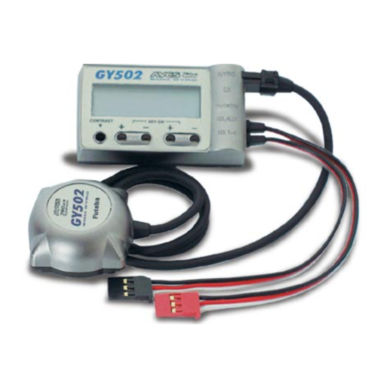
- Page 1 AVCS GYRO GY502 NSTRUCTION ANUAL YAW-AXIS STABILIZER FOR MODEL HELICOPTER (RATE GYRO)
- Page 2 •No part of this manual may be reproduced in any form without prior permission. •The contents of this manual are subject to change without prior notice. •This manual has been carefully written. Please write to Futaba if you feel that any corrections or clarifications should be made.
-
Page 3: Table Of Contents
DATA SETTING •Name and Function of Each Part ------------------------ 12 •LCD Display and Edit Keys ----------------------------- 13 •Function Map ---------------------------------------------- 14 •GY502 Functions Setting -------------------------------- 15 •Remote Gain Function ------------------------------------ 21 •Initialization ------------------------------------------------ 30 INSTALLATION AND ADJUSTMENT •Installing to Fuselage ------------------------------------- 32 •Flight Adjustments ---------------------------------------- 37... -
Page 4: For Safety
AFETY AFETY To ensure safe use, observe the following precautions. Meaning of Special Markings Pay special attention to the safety at the parts of this manual that are indicated by the following marks. Mark Meaning Procedures which may lead to a dangerous condition and cause death or serious injury to the user if not carried out properly. -
Page 5: Mounting/Operating Precautions
Mount the sensor and control amp so that metals or other conductive objects do not touch these cases. The GY502 uses a conductive resin case to reduce electromagnetic interference. Because the surface of the case is conductive, metal objects may cause a short circuit. - Page 6 AFETY Precautions When Turning on the Power Switch During initialization, the message “-Hello-” appears on the GY502 LCD screen. Do not move the helicopter until this message disappears (in about 3 seconds). Also, do not move the transmitter rudder stick from the neutral position during this period.
-
Page 7: Fuselage Maintenance Precautions
Never use the transmitter rudder trim in the AVCS mode. When the rudder is trimmed during flight, the neutral position will change. When using the GY502 in the AVCS mode, set revolution mixing to OFF. Fuselage Maintenance Precautions Use a tale rotor drive tube or other part with a high torsion performance for the tail drive. -
Page 8: Before Use
EFORE EFORE Set Contents After unpacking the GY502 set, first check if the following parts are provided: GY502 control amp (x1) GY502 sensor (x1) Sensor tape (x3) Mini screwdriver (x1) -
Page 9: Avcs Gyro
EFORE AVCS Gyro Differences Between AVCS Gyro and Conventional Gyro Compared to a convention gyro, the AVCS gyro has a substantially im- proved tail control capacity. Gyro operation also differs from that of conventional systems in a number of ways. The following sequentially describes the conventional gyro and the AVCS gyro. - Page 10 EFORE gyro controls the servo so that the movement of the tail stops, the same as a conventional gyro. At the same time, a sensor is controlled so that the tail is rotated in the opposite direction (returns to the original position). In short, the conventional gyro performs an operation known as "drifting stop", but the AVCS system performs an operation that "stops drifting and returns to original position".
-
Page 11: Digital Servo Compatibility
AVCS system differs from the conventional system. Digital Servo Compatibility Gyro performance largely depends on the servo used. The GY502 displays top performance when used with a digital servo. When using a digital servo, set the servo frame rate (Frm) function to High. -
Page 12: Data Setting
ETTING ETTING Name and Function of Each Part GY502 control amp LCD display Displays the set data. (8 characters X 1 line) (Input/output terminals) Gyro sensor input Rudder servo output (Receiver connectors) Edit keys Remote gain input Used when setting data. -
Page 13: Lcd Display And Edit Keys
ETTING LCD Display and Edit Keys LCD display Set data display and operation status monitoring are possible. Edit keys Setup screen call The setup screens can be sequen- tially called with the FUNC+ or FUNC- key. For the order in which the setup screens are called, see the function map. -
Page 14: Function Map
ETTING Function Map Power ON FUNC ”-” key Normal screen display (P15) FUNC ”+” key Power on screen display Gyro Reverse (P15) (P16) Gyro Gain Adjustment (P16) Rudder Control Gain (P17) Control Delay I (P17) Control Delay D (P17) Gain Tracking (P18) Operation Mode Setting (P18) -
Page 15: Gy502 Functions Setting
ETTING GY502 Functions Setting Power on screen display When the gyro power is turned on after the transmitter power was turned on, -Hello- blinks for about three seconds to initialize the data inside the gyro. During this period, do not move the transmitter rudder stick or the helicopter. - Page 16 ETTING Gyro Reverse Initial value: NOR Sets the gyro operation direction. NOR or REV can be selected. Set so that when the helicopter is banked right, left correction rudder is applied and when the helicopter is banked left, right correction rudder is applied.
- Page 17 ETTING Rudder Control Gain Initial value : ACG: 100%, NCG: 120% Adjusts the rudder stick operation gain. Setting range is 10% to 250%. AVCS and NOR mode gain can be set independently. In the AVCS mode, ACG is displayed and in the NOR mode, NCG is displayed. The display automatically changes to A or B according to the direction of the rudder stick and the gain of each direction can be set.
- Page 18 NOR mode. In the NOR mode, the GY502 operates the same as an ordinary gyro. In the AVC mode, the GY502 always operates in the AVCS mode. In the CM mode, the GY502 can be used in both the AVCS and NOR modes.
- Page 19 ETTING Servo Frame Rate Initial value : Low Switches the servo output pulses. The Low mode outputs pulses for an ordinary servo. Switch to the High mode only when using a digital servo. When using a servo that cannot be driven by high-speed pulses, other than a digital servo, never set servo frame rate to the High mode.
- Page 20 200% and limit setting is easy. A or B is displayed for the right and left directions. Note: When this screen is displayed, the GY502 does not operate as a gyro. To check operation, return to the initial screen, etc.
-
Page 21: Remote Gain Function
ETTING Remote Gain Function The remote gain function lets operator perform AVCS mode and Normal mode sensitivity adjustment and operation mode switching from the transmitter. The channel used here is called the "remote gain channel". (Channel 5 is used.) (Remote Gain Function) Receiver Transmitter GY501... - Page 22 The gain display indicates the actual gain at the GY502 normal screen display. The following shows the relationship between transmitter and gyro setting when GY502 sensitivity setting is 100% in both the G1 and G2 gain modes. - Relationship between transmitter and gyro setting Transmitter...
- Page 23 Actual gain The GY502 sensitivity is 0% at 50%. When set over 50%, the GY502 operates in the AVCS mode and when set under 50%, the GY502 operates in the Normal mode. When setting is changed 1%, the gyro...
- Page 24 The gain display indicates the actual gain at the GY502 normal screen display. The following shows the relationship between transmitter and gyro setting when GY502 sensitivity setting is 100% in both the G1 and G2 gain modes. - Relationship between transmitter and gyro setting Transmitter...
- Page 25 Use the following values as the sensitivity setting standard: Hovering Flight +40% AVCS mode +70% Normal mode -70% -40% Actual gain When set over 0%, the GY502 operates in the AVCS mode and when set under 0%, the GY502 operates in the Normal mode.
- Page 26 The gain display indicates the actual gain at the GY502 normal screen display. The following shows the relationship between transmitter and gyro setting when GY502 sensitivity setting is 100% in both the G1 and G2 gain modes. - Relationship between transmitter and gyro setting NORM...
- Page 27 Use the following values as the sensitivity setting standard: NORM IDL1 IDL2 SW-E Hovering Flight AVCS mode Normal mode Actual gain When set over 50%, the GY502 operates in the AVCS mode and when set under 50%, the GY502 operates in the Normal mode.
- Page 28 The gain display indicates the actual gain at the GY502 normal screen display. The following shows the relationship between transmitter and gyro setting when GY502 sensitivity setting is 100% in both the G1 and G2 gain modes. - Relationship between transmitter and gyro setting...
- Page 29 Adjust both the ATV rates to 90% at the transmitter Ch5 ATV function. [GY502 Settings] Operation Mode Setting function: Select the gyro operation mode at the GY502 Mode screen. (AVC, NOR, or CMT) Gyro Gain Adjustment function: Set the G:1 and G:2 gains at the GY502 G:x screen.
-
Page 30: Initialization
Initialization AVCS mode operation is based on the rudder neutral data stored in the GY502. When using the GY502 for the first time, or when the internal reference data and the transmitter neutral position differed when the transmitter neutral trim was adjusted, etc., the rudder neutral data must be read again. - Page 31 Never use the transmitter rudder trim in the AVCS mode. When the rudder is trimmed during flight, the neutral position will change. When using the GY502 in the AVCS mode, set revolution mixing to OFF. When the rudder neutral position was changed by the linkage, the rudder neutral position in the AVCS mode must always be re-read before use.
-
Page 32: Installation And Adjustment
Frame gyro bed directions. Install the GY502 sensor to the fuselage using the accessory sensor tape. Also routinely check the sensor tape and replace the tape if it is saturated with oil or partially peeled. - Page 33 NSTALLATION AND DJUSTMENT Connections Insert the connectors fully Connect the GY502, receiver and firmly. and servo as shown below. If a connector works loose due to vibration during flight, control may be lost and result in a dangerous situation. •Connect the sensor to the •Connect the rudder servo to...
- Page 34 NSTALLATION AND DJUSTMENT *However, when using the gyro in the CMT mode, since the AVCS and NOR mode gain must be set during hovering and in flight, a transmitter with a gyro mixing function (T9Zwc series, T8Usuper series) is necessary. •For a description of transmitter setting, see the remote gain function (p21).
- Page 35 •At this time, the GY502 gain display becomes 80% for hovering and 60% for flight. (*1) In the case of the T9Z GYR function, GY502 gain is 0% for a transmitter setting of 50%. When the gain is set above 50%, the GY502 operates in the AVCS mode and when the gain is set below 50%, the GY502 operates in the normal mode.
- Page 36 When using a transmitter without a gyro gain switching function, connect the gain setting connector to an idle channel and set the GY502 G1 and G2 gains using this gain setting screen. Gain can be trimmed by means of the transmitter ATV function.
-
Page 37: Flight Adjustments
When the transmitter rudder trim was adjusted, the rudder neutral data must be read to the GY502. Therefore, always perform the following operations: •Switch the transmitter sensitivity switch quickly (internal of within 1 second) between AVCS and Normal at least three times. - Page 38 Since the gyro gain also has a large effect on the stopping state, make this adjustment after adjusting the sensitivity. Adjust the rudder operation feel using the GY502 AVCS sense in the AVCS mode. (Steering angle, neutral suppression, and pirouette stopping)
- Page 39 NSTALLATION AND DJUSTMENT When you want to use rudder mixing in the Normal mode, set the transmitter so that rudder mixing is applied only during Normal mode operation. Never use rudder mixing in the AVCS mode.
-
Page 40: Reference
EFERENCE EFERENCE Specifications * Specifications are subject to change without prior notice. GY502 Ratings Yaw-axis stabilizer for helicopter (rate gyro) Display device: 8-character dot matrix liquid crystal display Operating voltage range: DC 3.8V to 6.0V Current drain: 70mA (@5.0V, including sensor) -
Page 41: Definition Of Abbreviations
EFERENCE Definition of Abbreviations The following defines the abbreviations and symbols used in this manual in alphabetical order. The function names are given on the description pages. ACGA/B Rudder control gain IDLE Transmitter power OFF state. (AVCS) p17 Use inhibited state. AFR function. -
Page 42: Gy502 Parameters Sheet
EFERENCE GY502 Parameters Sheet * Copy and use. Helicopter: Date: Initial Parameter value value Remarks GDir NOR/REV Gyro Reverse G:xx 100% 0-120% Gyro Gain Adjustment 100% 0-120% ACGA 100% 10-250% ACGx,NCGx ACGB 100% 10-250% NCGA 120% 10-250% Rudder Control Gain... - Page 43 EFERENCE FUTABA CORPORATION Makuhari Techno Garden Bldg., B6F 1-3 Nakase, Mihama-ku, Chiba 261-8555, Japan Phone: (043) 296-5118 Facsimile: (043) 296-5124 ©FUTABA CORPORATION 2000, 9...
Need help?
Do you have a question about the GY502 and is the answer not in the manual?
Questions and answers