Advertisement
SPECIFICATIONS
| Model | XTR-3060-XTS |
| Input voltage | 110/120V 60Hz |
| Dimensions | 9.0 x 4.5 x 6.0 in |
| Weight | 1.5 lbs /.65 kg |
| Working Environment | 32°F ~ 104°F / 0°C ~ 40°C |
| Storing Environment | -4°F ~ 176°F / -20°C ~ 80°C |
| Storage Humidity | 35%-45% |
| Temperature Range | 194°F ~ 896°F / 90°C ~ 480°C |
| Temperature Stability | ± 2°C (static) |
| Tip to Ground Resistance | <2Ω |
PACKAGE CONTENTS
- Main Power Unit with LED Display
- 75 Watt Soldering Iron with Ergonomic Grip
- Mini-Mag Lamp
- Attachable Helping Hands (set of two)
- Small Wrench (to Tighten Helping Hands)
- Anti-static Ground Wire Alligator Clip
- Solder Roll Holder (attaches to side of main unit)
- Brass Sponge Soldering Tip Cleaner with Cleaning Flux
- Wet Sponge Soldering Tip Cleaner
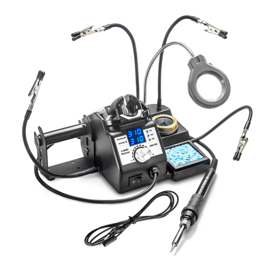
UNIT PARTS

- Helping Hands
- Soldering Iron Holder
- Solder Roll Holder
- Digital LED Temperature Readouts
- Power Switch
- Temperature Adjustment Knob
- Memory Preset Indicators
- Wet Sponge Tip Cleaner
- Brass Sponge with Rosin Flux Tip Cleaner
- Mini Mag Lamp
SET-UP & OPERATION

Do NOT leave the unit on full power for any long period of time. This will greatly reduce the life of your soldering iron.
- Remove all components from the box.
- Install the mini-mag lamp in the hole provided in the middle of the station.
- Install the helping hands to each side of the unit using the provided wrench to secure them.
- Plug the anti-static grounding wire with alligator clip into the back of the unit.
- Place the soldering iron in the soldering iron holder on the top of the left side of the unit.
![shock hazard]() Plug the 3-Prong AC cord into a grounded outlet to prevent electric shock or injury.
Plug the 3-Prong AC cord into a grounded outlet to prevent electric shock or injury.- Turn the power on by pressing the power switch on the bottom left of the control module.
- Once the power is on the LED Screen located on the front of the control module will light up.
- Set the desired working temperature by turning the aluminum knob on the front of the control module. The temperature of the soldering iron can be set anywhere from 194°F ~ 896°F/90°C ~ 480°C. The top number on the display indicates the actual temperature of the soldering iron at any given time. The bottom number indicates the set temperature.
- Moving the temperature adjustment knob clockwise will raise the temperature on the soldering iron, and rotating the temperature adjustment knob counterclockwise will lower the soldering iron tip temperature.
- Moisten the sponge and place it in the sponge holding space in the iron cradle.
 Plug the 3-Prong AC cord into a grounded outlet to prevent electric shock or injury.
Remove the iron from the cradle and flood the tip with a good quality rosin core solder-preferably 63/37 or 60/40 grade solder (See "Set-Up Operation").
- Wipe the tip across the moist sponge or dip the tip into the brass sponge to remove excess solder. The tip should then be bright and shiny.
- The soldering iron is now ready to solder. Proceed according to your standard working practice.
FUNCTION SETTINGS
FAHRENHEIT / CELSIUS CONVERSION
- Ensure the soldering iron is in the soldering iron holder.
- Turn on the power switch.
- Press and hold the aluminum temperature adjustment knob for about 2 seconds. The display will show "F" for Fahrenheit display mode.
- Turn the aluminum temperature adjustment knob to set the "F" (Fahrenheit) or "C" (Celsius) display.
- Wait for approximately 4 seconds and the program will save and exit on it's own.
SLEEP FUNCTION
When the soldering iron is placed in the holder, the iron will go into sleep mode after 5/10/30 minutes (depending on what you have the sleep timer set at). The display will show "SLP" on the bottom display to signify this and the temperature of the soldering iron will ramp down to 194°F / 200°C (shown on the top display). When the soldering iron is removed from the holder to use again, the temperature of the soldering iron will ramp back up to the temperature it was previously being used at within 5-10 seconds.
If you have this set to L00 the Sleep Function will NOT activate.
Setting the Sleep Timer
- Ensure the soldering iron is in the soldering iron holder.
- Turn on the power switch.
- Press and hold the aluminum temperature adjustment knob for about 2 seconds. The display will show "F" for Fahrenheit display mode.
- Press the temperature adjustment knob one more time and the display will show "L10". This indicates that the unit is set to go into sleep mode with 10 minutes of inactivity.
- You have four options for how long the unit sits idle until the sleep timer kicks in: 0, 5, 10 or 30 minutes. If you select L00, the unit will NOT go into sleep mode (this can reduce the life of your soldering iron and heating element).
- Adjust the temperature knob to change the sleep time. When the display indicates the sleep time you would like, wait for approximately 4 seconds and the program will save and exit on it's own.
TEMPERATURE CALIBRATION
- Ensure the soldering iron is in the soldering iron holder.
- Turn on the power switch.
- Press and hold the aluminum temperature adjustment knob for about 2 seconds. The display will show "F" for Fahrenheit display mode.
- Press the temperature adjustment knob two more times and the display will show "CAL", indicating you are now in Calibration Mode.
- Adjust the temperature knob to input the tested temperature, this will show on the top display. Press the temperature adjustment knob to confirm the temperature.
- Wait for approximately 4 seconds and the program will save and exit on it's own.
SETTING MEMORY PRESETS
- Ensure the soldering iron is in the soldering iron holder.
- Turn on the power switch.
- Press the temperature adjustment knob to select the memory preset channel (CH1/CH2/CH3).
- While the bottom display temperature is flashing, adjust the temperature adjustment knob to set the required temperature.
- When the temperatures stops flashing, the setting has been saved.
MAINTENANCE
SOLDERING TIP PREPARATION
- Keep the soldering tip properly tinned. Always use solder with sufficient rosin flux or the tip will de-wet. A well tinned tip will be bright all over when hot, with no dull or discolored spots.
- To tin the soldering iron tip:
- Plug in the iron and allow it to reach solder melt temperature.
- Flood the tip with solder and let it stand for one minute.
- Apply more solder to the tip, allow it to idle for one or two more minutes, wipe it lightly on the sponge. Do not remove all of the solder, but use the sponge to remove excess solder and wipe solder onto non-tinned areas.
- Do not file or attempt to reshape the tip. This will destroy the plating and shorten tip life. Do not use chloride and acid fluxes; they will also shorten tip and heater life.
- For maximum tip life, always apply solder to the heated connections or joints. Repeated application of solder directly to the tip will shorten the tip life.
Do NOT use anti-seize or any other lubricant on the tip retainer or heater of the soldering iron.
UNIT
- Keep the unit plugged into a GROUNDED outlet at all times during operation.
- Keep the unit and all components free from dirt, debris, and liquid at all times.
- Make sure the power cord is plugged in correctly and safely off the floor to prevent accidents.
- Keep all cords in the immediate workspace and avoid letting them hang off the side of a table or bench top.
- Wipe the unit down, when needed, with a dry, static-free cloth.

DISCONNECT POWER CORD BEFORE REPLACING A SOLDERING TIP AND/OR A HEATING ELEMENT
REPLACING THE SOLDERING TIP
- Turn off the soldering station, unplug the power cord from the power source and allow the soldering iron to cool down to room temperature. Never attempt to remove the tip while the iron is hot.
- Unscrew the small metal tip retaining screw cap at the bottom of the soldering irons metal shaft. Slide off or remove the soldering tip retaining collar. Now, remove the tip by sliding it forward.(There is NO need to remove the black Bakelite screw cap to change the tip.)
- Slide a new tip over the exposed ceramic heating element, slide the metal retaining collar over the new soldering tip back onto the soldering iron.
- Tighten the metal tip retaining screw cap to secure the tip into place. Do not over tighten the metal tip retaining screw cap.
- Plug the soldering iron AC cord into a grounded outlet to resume soldering.
Do NOT put excess pressure on the tip, it can damage the element.
BLACK BAKELITE SCREW CAP TIPS
- Bakelite is a strong and stable material when handled correctly. This part cannot be made of metal for heat transfer safety reasons.
- The black Bakelite screw cap does NOT need to be removed to replace the tip. This is only removed to access the heating element.
- The Bakelite screw cap should never be tightened or re-tightened when the iron is hot. If the iron is not at room temperature when the Bakelite screw cap is removed it can cause it to crack.
- When tightening the Bakelite screw cap, at room temperature, it only needs to be snug - DO NOT OVER-TIGHTEN.
REPLACING THE SOLDERING IRON HEATING ELEMENT

- Turn off the unit and unplug it from the outlet. Allow the soldering iron to cool down to room temperature.
Never attempt to handle the tip while the iron is hot. - Unscrew the Black Bakelite Screw Cap and slide off the full tip assembly.
- Push the Cord through the bottom of the soldering iron while simultaneously pulling gently on the heating element to expose the heating element circuit board.
- De-solder the 2 Thin (red or white) wires and the 2 Thick (blue) wires that have heat shielding on them from the circuit board and pull the heating element away from the board.
Please take note of the location of the wire thickness/color for installation of new heating element (see diagram below).

- On one side of the circuit board solder a thin wire to
![]() and a thick wire to
and a thick wire to ![]() (see diagram above).
(see diagram above). - Flip the circuit board over and solder a thin wire to
![]() and a thick wire to
and a thick wire to ![]() (see diagram above).
(see diagram above). - Pull the cord back gently and align the circuit board to the slots on the iron so the cord can be pulled back to its original position.
- Replace black Bakelite Screw Cap and screw back on and hand tighten -Do NOT over-tighten.
- Install the soldering tip, slide the metal soldering tip retaining collar and hand tighten it. Plug the AC cord back into a grounded outlet.

 and a thick wire to
  (see diagram above).
 and a thick wire to
  (see diagram above).
NOTE: The wires on the heating element can be soldered onto either side of the circuit board, as there is no polarity for the element.
TROUBLESHOOTING
| ISSUE | POSSIBLE SOLUTIONS |
Unit does not have power |
|
Soldering Iron Rattles |
|
S-E Error |
|
Tip is not heating up as expected |
|
Note: Normal temperature range for most soldering applications is 600°F ~ 650°F / 315°C ~ 343°C range. If you need to use a higher temperature, please use it for the shortest possible time. Using the soldering iron at exceedingly hot temperatures will shorten the life of the heating element and soldering iron.
SAFETY PRECAUTIONS
- When not in use always turn the power off and unplug the unit from the electrical outlet.
- Never use the soldering iron near any flammable substance, material, or gas.
![]()
Never touch the metallic components of the soldering iron while they are in use. The items are extremely hot and will cause serious burns instantly. Allow the unit to properly cool to room temperature before attempting to touch them.- Do not use the unit for any application other than soldering.
- Do not tap the soldering tip against the work surface to remove residual solder - this can damage the soldering tip and/or heating element.
- Do NOT modify the unit in any way.
- When replacing consumable parts, only use approved manufacturer parts.
- Do not get the unit wet or use when your hands are wet.
- The soldering process can produce smoke - ensure the area is well ventilated.

WARRANTY
HOW DO YOU OBTAIN WARRANTY SERVICE?
To obtain warranty service, you must call 844-861-4762 or email us at Info@XTronicUSA.com during the Warranty Period to open a service request. Proof of purchase will be required to open a service request.
QUESTIONS, PROBLEMS OR COMPLIMENTS?
For Any Questions, Problems, or Compliments please call or email us.
Toll Free: 844-861-4762
Info@XTronicUSA.com
Our Business Hours are:
Monday - Thursday: 8am - 4pm CST
Friday: 8am - Noon CST
If you would like to shop for other X-Tronic International Products Please visit our website
www.XTronicUSA.com
Documents / Resources
References

Download manual
Here you can download full pdf version of manual, it may contain additional safety instructions, warranty information, FCC rules, etc.
Advertisement


Need help?
Do you have a question about the 3060-PRO and is the answer not in the manual?
Questions and answers