Advertisement
GET STARTED
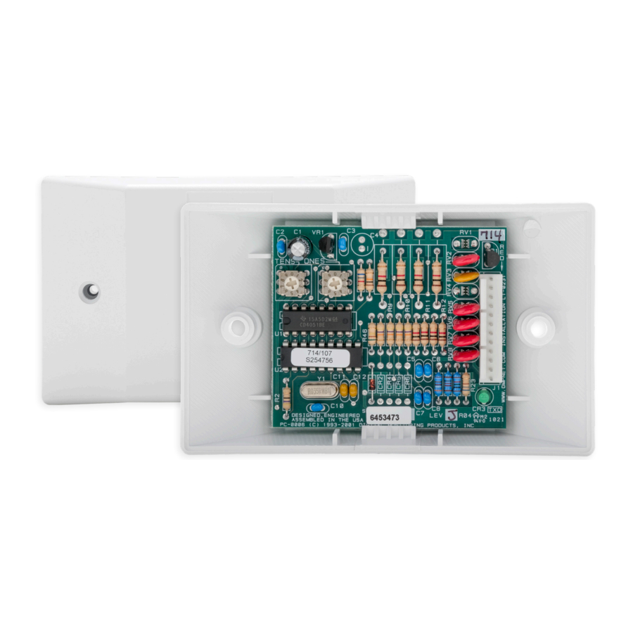
714 and 715 zone expander modules allow you to increase the number of reporting zones available on DMP panels. The modules connect to the panel Keypad Bus or LX‑Bus and are set to an address that determines the reporting zone number.
The 714 provides four 5 VDC Class B zones for use with burglary and non‑powered fire devices.
The 715 provides four 12 VDC Class B zones for use with burglary, non‑powered, or powered fire devices.
What's Included
- One 714 Zone Expansion Module or One 715 Zone Expansion Module
- (714) Four 1K Ohm Resistors
- (715) Four 3.3K Resistors
- 12‑Wire Harness
- Hardware Pack
INSTALLATION
Program the Panel
Program the zones on 714 or 715 zone expander modules with any of the panel's burglary or fire zone types.
You can also program zones as an Arming zone type when they are being used with key switches. For more information, refer to the appropriate panel programming guide.
Mount the Unit
The 714/715 comes in a high‑impact plastic housing that you can mount directly to a wall, backboard, or other flat surface. For easy installation, the housing base contains holes that allow you to mount the module on a single‑gang switch box or ring.
- Remove the housing fastener screws and separate the top housing from the base.
- Insert screws through the desired mounting holes on the housing base. Refer to Figure 1 for mounting hole locations.

- Tighten the screws into place.
- After wiring and addressing the module, attach the housing top to the mounted base with the housing fastener screws. Refer to Figure 2.
![]()


Wire the Unit
| SPECIFICATIONS | 714 MODULE | 715 MODULE |
| Normal Operating Range | 650‑2100 Ohms | 1200‑6000 Ohms |
| Zone Resistors | 1k Ohm EOL | 3.3k Ohm EOL |
| Max Line Impedence | 100 Ohms | 100 Ohms |
| Zone Supervision | All Zones | All Zones |
Table 1: 714 and 715 Modules Specifications

- 714 Module:
Connect Red to LX-Bus Wire or Panel Terminal 7
715 Module:
Connect Red to Panel Terminal 11 or a regulated, power limited power supply listed for Fire Protective Signaling through a Model 716 relay - To Keypad Bus or LX-Bus
See Figure 3.
Connect the 714 to the LX-Bus
To wire the 714, join the red, yellow, green, and black wires to a 4‑wire harness and connect it to the LX‑Bus.
Connect the 714 to the Keypad Bus
- Connect the red, yellow, green, and black wires to panel Terminals 7, 8, 9, and 10 respectively.
- Observe polarity and wire zones 1‑4.
- Install the included 1K Ohm EOL resistors.
Connect the 715 to the LX-Bus
To wire the 715, connect the red wire to panel Terminal 11 (Smoke power terminal). This allows Sensor Reset to drop power to the module and devices connected to its zones. Join the yellow, green, and black wires to a 4‑wire harness and connect it to the LX‑Bus.
Connect the 715 to the Keypad Bus
- Connect the red wire to panel Terminal 11 (Smoke power terminal). This allows Sensor Reset to drop power to the module and devices connected to its zones. Alternately, connect red to a regulated, power limited power supply listed for Fire Protective Signaling through a Model 716 relay. Use the Sensor Reset Output programming to drop power to the 715 module.
- Connect the yellow, green, and black wires to panel Terminals 8, 9, and 10 respectively.
- Observe polarity and wire zones 1‑4.
- Install the included 3.3K Ohm EOL resistors.
Set the Unit Address
714 and 715 Zone Expansion Modules use two rotary switches (TENS and ONES) to set the module address. For keypad bus addresses, set the switches to match the device address. For LX‑Bus addresses, set the switches to match the last two digits of the addresses. For example, for address 02 set the switches to TENS 0 and ONES 2 as shown in Figure 4. For more information, refer to Table 2 and Table 3.
| Table 2: LX-Bus Addresses and Corresponding Zone Numbers | ||||||
| SWITCH | XR SERIES, XF6 SERIES FIRE, AND XT75 CONTROL PANELS | XR550 AND XF6-500 CONTROL PANELS | ||||
| TENS | ONES | LX/LX500 | LX600 | LX700 | LX800 | LX900 |
| 0 | 0 | 500 | 600 | 700 | 800 | 900 |
| 0 | 1 | 501 | 601 | 701 | 801 | 901 |
| 0 | 2 | 502 | 602 | 702 | 802 | 902 |
| 0 | 3 | 503 | 603 | 703 | 803 | 903 |
| 0 | 4 | 504 | 604 | 704 | 804 | 904 |
| ... | ... | ... | ... | ... | ... | ... |
| 9 | 5 | 595 | 695 | 795 | 895 | 995 |
| 9 | 6 | 596 | 696 | 796 | 896 | 996 |
| 9 | 7 | 597 | 697 | 797 | 897 | 997 |
| 9 | 8 | 598 | 698 | 798 | 898 | 998 |
| 9 | 9 | 599 | 699 | 799 | 899 | 999 |
| Table 3: Keypad Bus Addresses and Corresponding Zone Numbers | ||||||
| KEYPAD BUS ADDRESS | SWITCH | ZONE NUMBERS | ||||
| TENS | ONES | XT SERIES, XR150, AND XF6-100 PANELS | XR550 AND XF6-500 PANELS | |||
| 1 | 0 | 1 | 11 to 14 | 11 to 14 | ||
| 2 | 0 | 2 | 21 to 24 | 21 to 24 | ||
| 3 | 0 | 3 | 31 to 34 | 31 to 34 | ||
| 4 | 0 | 4 | 41 to 44 | 41 to 44 | ||
| 5 | 0 | 5 | 51 to 54 | 51 to 54 | ||
| 6 | 0 | 6 | 61 to 64 | 61 to 64 | ||
| 7 | 0 | 7 | 71 to 74 | 71 to 74 | ||
| 8 | 0 | 8 | 81 to 84 | 81 to 84 | ||
| 9 | 0 | 9 | N/A | 91 to 94 | ||
| 10 | 1 | 0 | N/A | 101 to 104 | ||
| 11 | 1 | 1 | N/A | 111 to 114 | ||
| 12 | 1 | 2 | N/A | 121 to 124 | ||
| 13 | 1 | 3 | N/A | 131 to 134 | ||
| 14 | 1 | 4 | N/A | 141 to 144 | ||
| 15 | 1 | 5 | N/A | 151 to 154 | ||
| 16 | 1 | 6 | N/A | 161 to 164 | ||
ADDITIONAL INFORMATION
Wiring Specifications
DMP recommends using 18 or 22 AWG for all LX‑Bus and Keypad Bus connections. The maximum wire distance between any module and the DMP Keypad Bus or LX‑Bus circuit is 1,000 feet. To increase the wiring distance, install an auxiliary power supply, such as a DMP Model 505‑12. Maximum voltage drop between a panel or auxiliary power supply and any device is 2.0 VDC. If the voltage at any device is less than the required level, add an auxiliary power supply at the end of the circuit.
To maintain auxiliary power integrity when using 22‑gauge wire on Keypad Bus circuits, do not exceed 500 feet. When using 18‑gauge wire, do not exceed 1,000 feet. Maximum distance for any bus circuit is 2,500 feet regardless of wire gauge. Each 2,500 foot bus circuit supports a maximum of 40 LX‑Bus devices.
For additional information refer to the following documents:
- LX‑Bus/Keypad Bus Wiring Application Note (LT‑2031)
- 710 Bus Splitter/Repeater Module Installation Guide (LT‑0310)
Optional Accessories
You can replace the standard wiring harness with the optional 718T Plug‑in Screw Terminal. The enclosure base can also accommodate the 719T Terminal Boards for the 714 or the 720T Terminal Boards for the 715, both of which pass through panel LX‑Bus wiring. The 719T includes 1k EOL resistors. The 720T includes 3.3k EOL resistors.
LED Operation
The LED on the zone expanders flashes each time the module responds to a poll from the panel. If there is a problem with the hardware, panel programming, or the green data wire between the panel and the zone expander module, the LED stops flashing and System Trouble appears in the keypad display.
SPECIFICATIONS
| Operating Voltage | 12 VDC |
| 714 Operating Current | 7 mA + 1.6 mA per zone |
| 714 Zone Voltage | 5 VDC, max 2 mA |
| 715 Operating Current | 7 mA + 4 mA per active zone + 30 mA per smoke in alarm + 58 mA per zone shorted |
| 715 Zone Voltage | 12 VDC, max 34 mA per test results |
| Zone Operating Range | 9.7 to 14 VDC |
| Dimensions | 4.50 W x 2.75 H x 1.75 D in 11.43 W x 6.99 H x 4.45 D cm |
| Zones | 4 Supervised Class B Power Limited |
COMPATIBILITY
- XT Series Control Panels
- XR Series Control Panels
- XF6 Series Fire Control Panels
DMP
2500 North Partnership Boulevard
Springfield, Missouri 65803-8877
800.641.4282 | DMP.com
Documents / Resources
References
Download manual
Here you can download full pdf version of manual, it may contain additional safety instructions, warranty information, FCC rules, etc.
Advertisement


Need help?
Do you have a question about the 714 and is the answer not in the manual?
Questions and answers