Advertisement
- 1 PRODUCT SPECIFICATIONS SUMMARY
- 2 PANEL FEATURES
- 3 INSTALLATION
- 4 PRIMARY POWER SUPPLY
- 5 SECONDARY POWER SUPPLY
- 6 SYSTEM COMPONENTS
- 7 BELL OUTPUT
- 8 KEYPAD BUS
- 9 SMOKE AND GLASSBREAK DETECTOR OUTPUT
- 10 PROTECTION ZONES
- 11 POWERED ZONES FOR 2-WIRE SMOKE DETECTORS
- 12 DRY CONTACT RELAY OUTPUTS
- 13 ANNUNCIATOR OUTPUTS
- 14 WIRELESS BUS EXPANSION
- 15 LX-BUSTM/AX-BUSTM EXPANSION
- 16 ETHERNET CONNECTOR
- 17 PHONE LINE RJ CONNECTOR
- 18 RESET AND TAMPER HEADERS
- 19 CELLULAR MODULES
- 20 WI-FI CONNECTION
- 21 ACCESSORY DEVICES
- 22 Documents / Resources
PRODUCT SPECIFICATIONS SUMMARY
Power Supply
| Transformer Input: | Model 327, plug-in — Primary input: 120 VAC, 60 Hz, Secondary output: 16.5 VAC 50 VA Model 322/323, wire-in — Primary input: 120 VAC, 60 Hz, Secondary output: 16 VAC 56 VA Model 324/324P, wire-in — Primary input: 120 VAC, 60 Hz, Secondary output: 16V AC 100 VA |
| Standby Battery: | 12 VDC, 1.0 Amps Max. charging current on Models 364, 365, 366, 368, or 369 Replace every 3 to 5 years |
| Auxiliary: | 12 VDC output at 1.5 Amp Max 12 VDC output at 325 mA used with two Model 364 batteries in the Model 341 enclosure |
| Bell Output: | 12 VDC at 1.5 Amp Max |
All circuits are inherent power limited except the red battery wire and AC terminal.
See 50 VA-75VA 3-Pin Header for Transformer Types section for panel output 2 Amp or 3 Amp current limitations.
Communication
- Built-in network communication to DMP Model SCS-1R or SCS-VR Receivers
- Built-in 128-bit or 256-bit encrypted communication to DMP Model SCS-1R or SCS-VR Receivers (XR550E Series)
- Built-in Contact ID communication to DMP Model SCS-1R Receivers
- Optional 893A Dual Phone Line Module with phone line supervision
- Optional 763 Wi-Fi Module
- Optional 263LTE Cellular Module
- Can operate as a local panel
256-bit encrypted messages to SCS-1R receiver only communicate when using SCS-104 Receiver Line Cards with Version 102 or higher software.
Panel Zones
- Eight 1k or 2.2k Ohm EOL burglary zones (zones 1 to 8)
- Two 3.3k Ohm EOL powered zone with reset (zones 9 and 10)
Keypad Bus
You can connect up to a total of 16 of the following supervised keypads and expansion modules to keypad bus:
- Alphanumeric keypads
- Graphic Touchscreen keypads
- Four, Eight-and/or single-zone expansion modules
- Single-zone detectors
- Access control modules
- Wireless Keypads (maximum of 7)
LX500-LX900 Bus™
You can connect the following devices to the LX-Bus™ connections provided on the panel:
- Four, eight, sixteen, and/or single-zone expansion modules
- Single-zone detectors
- Relay output expansion modules
Outputs
The XR150/XR550 Series provide two Single Pole, Double Throw (SPDT) relay outputs which require the installation of two Model 305 relays, each rated 1 Amp at 30 VDC resistive (power limited sources only). A Model 431 Output Harness is required to use these outputs.
The XR150/XR550 Series panels also provide four open collector outputs rated for 50mA each. The open collector outputs provide ground connection for a positive voltage source. A Model 300 Output Harness is required to use these outputs.
Enclosure Specifications
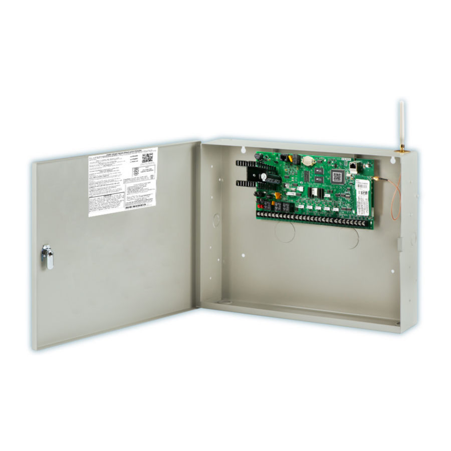
The XR150/XR550 Series panels are shipped in an enclosure with a transformer, end-of-line resistors, battery leads, and a user guide.
| Enclosure Model | Size | Color(s) | Construction (Cold Rolled Steel) |
| 350 | 17.5"W x 13.5"H x 3.5"D | Gray (G) or Red (R) | 18-Gauge |
| 350A | 17.5"W x 13.5"H x 3.75"D | Gray (G) | 18-Gauge with 16-Gauge door |
| 341 | 13.22"W x 7.0"H x 3.5"D | Gray (G) | 20-Gauge |
| 349 | 12.5"W x 11.5"H x 3.5"D | Gray (G) | 20-Gauge |
| 352X | 14.5"W x 32.0"H x 4.0"D | Gray (G) | 16-Gauge |
PANEL FEATURES
Description
The DMP XR150/XR550 Series system is a versatile 12 VDC, combined access control, burglary, and fire panel with battery backup. The panels provide eight on-board burglary zones and two on-board 12 VDC Class B powered zones. The powered zones have a reset capability to provide for 2-wire smoke detectors, relays, or other latching devices.
Combined current requirements of additional modules may require an auxiliary power supply. Refer to the Power Requirements section in this guide when calculating power requirements. The panels can communicate to DMP SCS1R or SCS-VR Receivers using digital dialer, cellular, network, Contact ID, or encrypted communication.
Zone Expansion
The XR550 panel provides multiple options for zone expansion:
| Panel | Programming Zone Number |
| Onboard | 1-10 |
| Keypad Bus | Programming Zone Number |
| 1 | 11-14 |
| 2 | 21-24 |
| 3 | 31-34 |
| 4 | 41-44 |
| 5 | 51-54 |
| 6 | 61-64 |
| 7 | 71-74 |
| 8 | 81-84 |
| 9 | 91-94 |
| 10 | 101-104 |
| 11 | 111-114 |
| 12 | 121-124 |
| 13 | 131-134 |
| 14 | 141-144 |
| 15 | 151-154 |
| 16 | 161-164 |
| 1100 Series Wireless | Programming Zone Number |
| 1144 Series Key Fob | 400-449 |
| LX-Bus | Programming Zone Number |
| LX-Bus 500 | 500-599 |
| LX-Bus 600 | 600-699 |
| LX-Bus 700 | 700-799 |
| LX-Bus 800 | 800-899 |
| LX-Bus 900 | 900-999 |
Do not use shielded or twisted pair wiring for LX-Bus or Keypad Bus circuits.
Output Expansion
In addition to the two SPDT relays and four programmable open collector outputs on the XR150/XR550 Series, you can also connect up to 25 programmable Model 716 Output Expansion Modules to each LX-Bus. These modules can provide an additional 500 or 100 programmable SPDT relays.
The panels provide Output Schedules for programming the 716 to perform a variety of annunciation and control functions. Also assign the 716 outputs to any panel Output Options such as Fire Alarm, Communication Fail, or Phone Trouble Outputs. To follow Keypad Bus addresses nine through 16, install multiple 716 modules. Refer to the 716 Installation Guide (LT-0183).
Central Station Communication
The panel reports to DMP SCS-VR or SCS-1R Receivers using digital dialer, cellular, network, or Contact ID communication. The panels connect at the premises to a standard RJ31X or RJ38X telephone jack. When connecting the panel to two separate phone lines in fire or burglary applications, use the DMP 893A Dual Phone Line Module.
Encrypted Communications (XR550 with Network & Encryption Only)
The XR550 panel can communicate using AES encryption. If you currently have an XR550 panel with network capability, you may contact DMP Customer Service with the panel serial number. The serial number(s) should be sent in writing via e-mail. A separate feature key is sent for each panel to activate encrypted communications using the Feature Upgrade process. Encrypted communication cannot be enabled on a XR550 panel without network communication capabilities. For more information on the Feature Upgrade process see the XR150/XR550 Series Programming Guide (LT-1232). 256-bit encrypted messages to SCS-1R receiver only communicate when using SCS-104 Receiver Line Cards with Version 102 or higher software.
Caution Notes
Throughout this guide you will see caution notes containing information you need to know when installing the panel. These cautions are indicated with a yield sign. Whenever you see a caution note, make sure you completely read and understand its information. Failing to follow the caution note can cause damage to the equipment or improper operation of one or more components in the system. See the example shown below.
Always ground the panel before applying power to any devices: The panel must be properly grounded before connecting any devices or applying power to the panel. Proper grounding protects against Electrostatic Discharge (ESD) that can damage system components.
Compliance Instructions
![]() For applications that must conform to a local authorities installation standard or a National Recognized Testing Laboratory certificated system, please see the Compliance Listing Guide LT-1330 for additional instructions.
For applications that must conform to a local authorities installation standard or a National Recognized Testing Laboratory certificated system, please see the Compliance Listing Guide LT-1330 for additional instructions.
INSTALLATION
Mounting the Enclosure
The metal enclosure for the XR150/XR550 Series must be mounted in a secure, dry place to protect the panel from damage due to tampering or the elements. It is not necessary to remove the panel PCB when installing the enclosure.

Figure 1: XR550 Series in Model 350 or 350A Enclosure
The 350A Attack Resistant enclosure is factory shipped with one knockout on the top left of the enclosure. As needed, additional knockouts or antenna exits may be added at the time of installation. See figure for the positions on the enclosure that can be added. Each additional knockout must be filled with conduit.

Figure 2: XR550 Series in Model 341 Enclosure

Figure 3: XR550 Series in Model 352X Enclosure and Separate 352S Enclosure with Shelves
Connecting LX-Bus™, AX-Bus™ and Keypad Bus Devices
You can connect devices to the LX-Bus/AX-Bus and Keypad Bus through the PROG, LX500, LX600, LX700, LX800, and LX900 4-pin headers and the keypad bus. Several factors determine the DMP LX-Bus/AX-Bus and keypad bus performance characteristics including the wire length and gauge use, the number of devices connected, and the voltage at each device. When planning an LX-Bus/AX-Bus and keypad bus installation, keep in mind the following information:
- DMP recommends using 18 or 22-gauge unshielded wire for all LX-Bus/AX-Bus and keypad circuits. Do not use twisted pair or shielded wire for LX-Bus/AX-Bus and keypad bus data circuits.
- On keypad bus circuits, to maintain auxiliary power integrity when using 22-gauge wire do not exceed 500 feet. When using 18-gauge wire do not exceed 1,000 feet. To increase the wire length or to add devices, install an additional power supply that is listed for Fire Protective Signaling, power limited, and regulated (12VDC nominal) with battery backup. Each panel allows a specific number of supervised keypads. Add additional keypads in the unsupervised mode. Refer to the Keypad Bus section for the specific number of supervised keypads allowed.
- Maximum distance for any one bus circuit (length of wire) is 2,500 feet regardless of the wire gauge. This distance can be in the form of one long wire run or multiple branches with all wiring totaling no more than 2,500 feet. As wire distance from the panel increases, DC voltage on the wire decreases. Maximum number of LX-Bus/ AX-Bus devices on the first 2,500 foot circuit is 40 devices.
- Maximum voltage drop between the panel (or auxiliary power supply) and any device is 2.0VDC. If the voltage at any device is less than the required level, add an auxiliary power supply at the end of the circuit. When voltage is too low, the devices cannot operate properly.
PRIMARY POWER SUPPLY
AC Terminals 1 and 2
Connect the transformer wires to terminals 1 and 2 on the panel. Use no more than 70 ft. of 16 gauge or 40 ft. of 18 gauge wire between the transformer and the panel.
Always ground the panel before applying power to any devices: The XR150/XR550 Series must be properly grounded before connecting any devices or applying power to the panel. Proper grounding protects against Electrostatic Discharge (ESD) that can damage system components. See the Earth ground section.
Transformer Types
Use Model 327 (16.5 VAC 50 VA) plug-in or Model 322/323 (16 VAC 56 VA), or 324/324P (16 VAC 100 VA) wire-in transformer. Use Model 322/323 or 324/324P wire-in transformers when required by the Authority Having Jurisdiction (AHJ).
The transformer must be connected to an unswitched 120 VAC 60 Hz electrical outlet with at least.87A of available current. Never share the transformer output with any other equipment.
50VA-75VA 3-Pin Header for Transformer Types
Place the jumper on the left two pins labeled 50VA for a Maximum 2 Amp (Bell+Aux+Smoke+XBUS+LX500-LX900) when using the Model 322/323 56VA, or 327 50VA plug-in transformer (default).
Place the jumper on the right two pins labeled 75VA for a Maximum 3 Amp (Bell+Aux+Smoke+XBUS+LX500-LX900) when using the Model 324/324P 100 VA wire-in transformer.
SECONDARY POWER SUPPLY
Battery Terminals 3 and 4
Connect the black battery lead to the negative battery terminal. The negative terminal connects to the enclosure ground internally through the XR150/XR550 Series circuit board. Connect the red battery lead to the battery positive terminal.
You can add a second battery in parallel using the DMP Model 318 Dual Battery Harness.
DMP requires each battery be separated by a PTC (Positive Temperature Coefficient switch) in the battery harness wiring to protect each battery from a reversal or short within the circuit.
Use sealed lead-acid batteries only: Use the DMP Model 364 (12VDC 1.3Ah), Model 365 (12VDC 9 Ah), Model 366 (12VDC 18 Ah), Model 368 (12VDC 5.0 Ah), or Model 369 (12VDC 7 Ah) sealed lead-acid rechargeable battery. Batteries supplied by DMP have been tested to ensure proper charging with DMP products. GEL CELL BATTERIES CANNOT BE USED WITH THE XR150/XR550 SERIES PANEL.
Earth Ground (GND)
The XR150/XR550 Series panel terminal 4 can be connected to earth ground (if available) using 14 gauge wire or larger. Additional options are cold water pipe or ground rod. Gas pipes or sprinkler pipes should not be used. Do not connect to an electrical ground or server rack. A ground connection is not required to provide normal system operation.
If you require ground fault detection, use the DMP Model 271 Ground Fault Detection Module to detect a ground fault without harming the control panel. Connect the module to a zone and the earth ground (if available) using 14 gauge wire or larger to detect a ground fault.
Battery Only Start
When powering up the XR150/XR550 Series panel without AC power, briefly short across the battery start pads to pull in the battery cutoff relay. The leads need a momentary short only. Once the relay has pulled in, the battery voltage holds it in that condition. If the XR150/XR550 Series panel is powered up with an AC transformer, the battery cutoff relay is pulled in automatically.
Battery Replacement Period
DMP recommends replacing the battery every 3 to 5 years under normal use.
Discharge/Recharge
The XR150/XR550 Series battery charging circuit float charges at 13.8 VDC at a maximum current of 1.0 Amps using a 50 VA or 56 VA transformer. Listed below are the various battery voltage level conditions:
| Battery Trouble: | Below 11.9 VDC |
| Battery Cutoff: | Below 10.2 VDC |
| Battery Restored: | Above 12.6 VDC |
Battery Supervision
The XR150/XR550 Series tests the battery when AC power is present. The test is done every three minutes and lasts for five seconds. During the test, the panel places a load on the battery; if the battery voltage falls below 11.9VDC a low battery is detected. If AC power is not present, a low battery is detected any time the battery voltage falls below 11.9 VDC.
If a low battery is detected with AC power present, the test repeats every two minutes until the battery charges above 12.6 VDC indicating the battery has restored voltage. If a weak battery is replaced with a fully charged battery, the restored battery will not be detected until the next two minute test is completed.
Battery Cutoff
The panel disconnects the battery any time the battery voltage drops below 10.2 VDC. This prevents battery deep discharge damage.
Power Requirements
During AC power failure, the XR150/XR550 Series panel and all connected auxiliary devices draw their power from the battery. All devices must be taken into consideration when calculating the battery standby capacity. The following table lists the XR150/XR550 Series panel power requirements. You must add the additional current draw of keypads, zone expansion modules, smoke detector output, and any other auxiliary devices used in the system for the total current required. The total is then multiplied by the number of standby hours required to calculate the total ampere hours required.


Standby Battery Selection
To choose the type and number of batteries needed for 24, 60, or 72 hours of standby power based on the Amp Hours Required calculation for XR150/XR550 Series Power Requirements, perform the following:
- Select the desired standby hours required from the table below: 24, 60, or 72 hours.
- Select the desired battery size:
Model 368 (12 VDC 5.0 Ah),
Model 369 (12 VDC 7 Ah),
Model 365 (12 VDC 9 Ah),
Model 366 (12 VDC 18 Ah), or
Model 364 (12 VDC 1.3 Ah) when used in the Model 341 enclosure. - Select a Max. Ah Available number that is just greater than the number calculated in Amp Hours Required.
- Install the number of batteries shown in the corresponding No. of Batteries required column.
You can use either a Model 327 Plug-in 50 VA or Model 322/323 Wire-in 56 VA with up to 36 Ah of batteries. The Model 324/324P Wire-in 100 VA Transformer may be used with any of the battery choices listed below.
For listed installations, batteries can be installed in a DMP Model 349, 350 or 352S enclosure and all wiring shall run through conduit. The enclosure shall be installed to the left of the XR150/XR550 Series enclosure to ensure Battery and AC wire separation.
24 Hours of Standby Power

60 Hours of Standby Power

72 Hours of Standby Power

72 hours is the typical battery recharge time required for any of the Number of Batteries shown in this section.
If the Amp Hours Required calculation is greater than any Max. Ah Available number shown on a table, then add power supply(s) to power some system devices allowing the Amp Hours Required calculation to be reduced.
SYSTEM COMPONENTS
Wiring Diagram

Figure 4: XR550 Series Wiring Diagram

Incorrect connections may cause damage to the unit.

DO NOT USE LOOPED WIRE UNDER TERMINALS. BREAK WIRE RUN TO PROVIDE SUPERVISION OF CONNECTIONS.
![]()
THIS UNIT MAY BE PROGRAMMED TO USE AN ALARM VERIFICATION FEATURE THAT RESULTS IN DELAY OF THE SYSTEM ALARM SIGNAL FROM THE INDICATED CIRCUITS. THE TOTAL DELAY (CONTROL UNIT PLUS SMOKE DETECTORS) SHALL NOT EXCEED 60 SECONDS. NO OTHER SMOKE DETECTOR SHALL BE CONNECTED TO THESE CIRCUITS UNLESS APPROVED BY THE LOCAL AUTHORITY HAVING JURISDICTION (AHJ).
Lightning Protection
Metal Oxide Varistors and Transient Voltage Suppressors help protect against voltage surges on panel input and output circuits. Additional surge protection is available by installing the DMP 370 or 370RJ Lightning Suppressors or Model 270 Network Transient Suppression Module.
BELL OUTPUT
Terminals 5 and 6
Terminal 5 supplies positive 12 VDC to power alarm bells or horns. This output can be steady, pulsed, or temporal depending upon the Bell Action specified in Bell Options. Terminal 6 is the ground reference for the bell circuit. This supervised output detects 1k Ohms or less as normal. The indicating appliance can supply this resistance. If using a horn or siren, a 1k Ohm 1/2 W EOL resistor (provided) should be added across the bell circuit to provide supervision. See the Notification Appliance section for a list of approved notification appliances and the Wiring Diagrams for connections.
KEYPAD BUS
Description
XR150/XR550 Series panel terminals 7, 8, 9, and 10 are for the keypad bus. You can connect up to 16 supervised keypads to the XR550 Series and 8 supervised keypads to the XR150 Series as well as multiple unsupervised keypads. In addition to DMP keypads, you can also connect any combination of zone expansion modules to the data bus up to a total of 16 devices. Do not use shielded wire for LX-Bus/Keypad Bus circuits.
Terminal 7 - RED
This terminal supplies positive 12 VDC regulated to power DMP keypads and zone expansion modules. Terminal 7 also supplies power for any auxiliary device. The ground reference for terminal 7 is terminal 10.
The output current is shared with the smoke power output on terminal 11 and zones 9 and 10. Current draw for all connected devices must not exceed the panel maximum current rating. See Power Supply in the Compliance section for maximum current in a fire listed application.
Terminal 8 - YELLOW
Terminal 8 receives data from keypads and zone expansion modules. It cannot be used for any other purpose.
Terminal 9 - GREEN
Terminal 9 transmits data to keypads and zone expansion modules. It cannot be used for any other purpose.
Terminal 10 - BLACK
Terminal 10 is the ground reference for DMP keypads, zone expansion modules, and all auxiliary devices being powered by terminal 7.
Programming (PROG) Connection
A 4-pin header PROG header is provided to connect a keypad when using a DMP Model 330 Programming Cable. This provides a quick and easy connection for panel programming.
You may also use the PROG Header to connect Keypad Bus devices. This is an alternative to connecting keypad bus devices to terminals 7, 8, 9, and 10. The programming keypad must be set to address 1.
Keypad Bus LEDs
The two LEDs, located above the PROG header, indicate data transmission and receipt. The left LED flashes green to indicate the panel is transmitting keypad bus data. The right LED flashes yellow to indicate the panel is receiving keypad bus data.
OVC LED(s)
The Overcurrent LED (OVC) lights up red when the devices connected to the Keypad Bus and LX-Bus(es) draw more current than the panel is rated for. The LED(s) turn a steady Red when lit. When the OVC LED(s) light up red, the appropriate LX-Bus(es) and Keypad bus are shut down.
- The OVC LED located to the left of the 893A connector indicates overcurrent for the Keypad Bus (Terminals 7-10 and PROG header), XBUS, and LX500-LX700.
- The OVC LED to the right of the CELL MODULE connector indicates overcurrent for LX800-LX900.
SMOKE AND GLASSBREAK DETECTOR OUTPUT
Terminals 11 and 12
Terminal 11 supplies positive 12 VDC regulated to power 4-wire smoke detectors and other powered devices. This output can be turned off by the user for 5 seconds using the Sensor Reset User Menu option to allow latched devices to reset. Terminal 12 is the ground reference for terminal 11.
Current Rating
The Output current from terminal 11 is shared with terminals 7, 25, 27, and LX500-LX900.
The total current draw of all devices powered from the panel must be included with terminal 11 calculations and must not exceed the maximum output rating.
PROTECTION ZONES
Terminals 13–24
Zones 1 to 8 (terminals 13 to 24) on the XR150/XR550 Series panel are all grounded burglary zones. For programming purposes, the zone numbers are 1 through 8. Listed below are terminal 13 to 24 connection functions.
| Terminal | Function | Terminal | Function |
| 13 | Zone 1 voltage sensing | 19 | Zone 5 voltage sensing |
| 14 | Ground for Zones 1 and 2 | 20 | Ground for Zones 5 and 6 |
| 15 | Zone 2 voltage sensing | 21 | Zone 6 voltage sensing |
| 16 | Zone 3 voltage sensing | 22 | Zone 7 voltage sensing |
| 17 | Ground for Zones 3 and 4 | 23 | Ground for Zones 7 and 8 |
| 18 | Zone 4 voltage sensing | 24 | Zone 8 voltage sensing |
The voltage sensing terminal measures the voltage across a 1k Ohm End-of-Line resistor to ground. Use DMP Model 311 1k Ohm resistors. Dry contact sensing devices can be used in series (normally-closed) or in parallel (normally-open) with any of the burglary protection zones.

Figure 5: End-of-Line Resistors
Operational Parameters
Each protection zone detects three conditions: Open, Normal, and Short. Listed below are voltage and resistance parameters for each condition:
Zone Response Time
A condition must be present on a zone for 500 milliseconds before it is detected by the XR150/XR550 Series panel. Ensure detection devices used on the protection zones are rated for use with this delay. Zones 1-10 can also be programmed for a fast response delay of 160 milliseconds.
| Zone Voltages Using 2.2k Ω Resistors | |
| State | Voltage |
| Short | - 2.1 VDC |
| Normal | 2.2 - 2.9 VDC |
| Open | ≥ 3 VDC |
| Applies to zones 1-9 on XR Series panels with Version firmware and higher | |
Keyswitch Arming Zone
Using a keyswitch on an Arming type zone allows you to arm and disarm selected areas without having to enter a user code.
POWERED ZONES FOR 2-WIRE SMOKE DETECTORS
Terminals 25–26 and 27–28
Panel terminals 25 through 28 provide two resettable Class B, Style A, 2-wire powered zones. For programming purposes the zone numbers are 9 and 10.
The maximum wire length for either zone 9 or zone 10 is 3000 feet using 18 AWG or 1000 feet using 22 AWG. The maximum voltage is 13.8 VDC and the maximum normal standby current is 1.25 mA DC. The maximum line impedance is 100 Ohms. The maximum short circuit current is 56 mA. When using zone expansion modules, use Model 309 EOL resistors. The compatibility identifier for the zones is A.
Do not mix detectors from different manufacturers on the same zone.
Performing a Sensor Reset momentarily drops power to the devices on zones 9 and 10. The panel views these zones (9 and 10) as "Open" while the power is absent.
Refer to the Compliance Listing Guide LT-1330 for list of Compliance 2-wire smoke detectors.
DRY CONTACT RELAY OUTPUTS
Description
The XR150/XR550 Series panel provides two programmable auxiliary SPDT relays when equipped with two DMP Model 305 relays in sockets OUTPUT 1 and OUTPUT 2 and a Model 431 Output Harness on the OUT1-OUT2 6-pin Header. Each relay provides one SPDT set of contacts that can be operated by any of the functions listed below:
- Activation by zone condition: Steady, Pulsing, Momentary, and Follow
- Activation by 24-hour 7-day schedule: One on and one off time a day for each relay
- Manual activation from the DMP keypad menu
- Communication failure
- Armed area annunciation
- Fire Alarm, Fire Trouble or Supervisory
- Ambush Alarm
- Exit and Entry timers
- System Ready
- Late to Close
- Panic Alarm
- Ready
- Armed
- Disarmed
- Burglary
- Phone Trouble
- Device Fail
- Sensor Rest
- Closing Wait
Contact Rating
The Model 305 relay contacts are rated for 1 Amp at 30 VDC (allows.35 power factor). Connect auxiliary power to the Relay Output 1 common terminal by installing the gray harness wire to terminal 7. Current draw for all connected devices must not exceed the panel maximum current rating.
Model 431 Output Harness Wiring
The relay contacts are accessible by installing the DMP 431 Output Harness on the 6-pin OUT1-OUT2 header. OUTPUT 2 uses the top three prongs, and OUTPUT 1 uses the bottom three prongs. The wire harness and contact locations are shown below:
| Contact | Color |
| Output 2 normally open | Orange with White Stripe |
| Output 2 common | White with Gray Stripe |
| Output 2 normally closed | Violet with White Stripe |
| Output 1 normally open | Orange |
| Output 1 common | Gray |
| Output 1 normally closed | Violet |
ANNUNCIATOR OUTPUTS
Description
The four programmable annunciator outputs can be programmed to indicate the activity of the panel zones or conditions occurring on the system. Annunciator outputs do not provide a voltage but instead switch-to-ground a voltage from another source. The outputs can respond to any of the conditions listed in the Description section for Dry Contact Relays. Maximum voltage is 30 VDC at 50 mA.
Model 300 Harness Wiring
Access the open collector outputs by installing DMP 300 Harness on the 4-pin OUTPUTS header. The output locations are shown below. For listed applications, devices connected to the outputs must be located within the same room as the panel.
| Output | Color | Wire |
| 3 | Red | 1 |
| 4 | Yellow | 2 |
| 5 | Green | 3 |
| 6 | Black | 4 |
Model 860 Relay Module
Connect a Model 860 Relay Module to the OUTPUTS header on the XR150/XR550 Series panel to provide relays for outputs 3-6.
Use these relays for electrical isolation between the alarm panel and other systems or for switching voltage to control various functions. Power is supplied to the relay coils from a single wire connected to the panel auxiliary power terminal 7. The module includes one relay and provides three additional sockets for expansion of up to four relays. Mount the 860 inside the panel enclosure using the 3-hole pattern and plastic standoffs. Refer to the 860 Module Install Sheet (LT-0484) as needed.
Relay Contact Rating: 1 Amp at 30 VDC (allows.35 power factor)
WIRELESS BUS EXPANSION
Description
The X-BUS Wireless Bus header provides connection for the 1100XH/1100XHE Wireless Receiver. The X-BUS provides up to 500 wireless zones numbered 500-999. Refer to the 1100XH Series Wireless Receiver Install Guide (LT-1823) for complete information.
- XR150 provides up to 100 wireless zones
- XR550 provides up to 500 wireless zones
Wireless Bus LEDs
The two LEDs, located above the X-Bus header, indicate data transmission and receipt. The left LED flashes green to indicate the panel is transmitting data. The right LED flashes yellow to indicate the panel is receiving data.
LX-BUSTM/AX-BUSTM EXPANSION
LX-Bus/AX-Bus Headers
XR Series control panels are capable of providing zone, output, and access control expansion by connecting hardware modules to the AX/LX-Bus headers on the control panel. XR150 panels are manufactured with one LX-Bus header labeled LX500. AX-Bus operation does not apply to XR150 panels. XR550 panels are manufactured with five AX/LX-Bus headers labeled LX500-LX900.
LX-Bus (XR150/XR550)
LX-Bus operation is compatible with hardwired zone and output expanders. Each LX-Bus represents 100 addresses.
")
Figure 6: LX-Bus Headers and LEDs
- LX500, provides zones/outputs 500-599 (XR150, XR550)
- LX600, provides zones/outputs 600-699 (XR550 only)
- LX700, provides zones/outputs 700-799 (XR550 only)
- LX800, provides zones/outputs 800-899 (XR550 only)
- LX900, provides zones/outputs 900-999 (XR550 only)
AX-Bus (XR550)
AX-Bus operation is compatible only with XR550 control panels and DMP Model 734, 734N, and 734N-POE Access Control Modules. All four door access modules provide one Form-C relay output and expansion zones. AX-Bus operation is not compatible with addressable zone and output expanders. Each AX-Bus represents predetermined addresses for 734, 734N, and 734N-POE operation: 16 addresses for door relay outputs, and 64 addresses for expansion zones.
Device Addresses and 734, 734N, and 734N-POE Zone Numbers
")
Device Addressing
Addressable expanders and door controllers identify themselves to the control panel by their programmed address, which allows the panel to uniquely identify devices. An addressable device's address determines which numbers the zones, outputs and door controllers will be assigned in programming. Refer to the device's installation guide for addressing information.
LX-Bus/AX-Bus LEDs
The two LEDs, located above each LX-Bus/AX-Bus header, indicate data transmission and receipt. The left LED flashes green to indicate the panel is transmitting LX-Bus/AX-Bus data. The right LED flashes yellow to indicate the panel is receiving LX-Bus/AX-Bus data.
OVC LEDs
The Overcurrent LED (OVC) lights red when the devices connected to the Keypad Bus and LX-Bus(es) draw more current than the panel is rated for. The LED(s) turn a steady red when lit. When the OVC LED(s) lights red, the appropriate LX-Bus(es) and Keypad Bus are shut down.
- The OVC LED located to the left of the 893A connector indicates overcurrent for the Keypad Bus (Terminals 7-10 and PROG header), XBUS, and LX500-LX700.
- The OVC LED to the right of the CELL MODULE connector indicates overcurrent for LX800-LX900.
ETHERNET CONNECTOR
Description
The ETHERNET Connector is available on the XR150/XR550 with network or encryption to connect directly to an Ethernet network using a standard patch cable. The ETHERNET Connector supports 100 Mb/s full duplex operation and the maximum impedance is 100 Ohms.
Ethernet LEDs
The two LEDs, located on the top edge of the ETHERNET Connector, indicate J1 network connection. The left Link LED lights up yellow when connected to a 100 Mb network and is off when connected to a 10 Mb network. The right, Activity LED lights up green to indicate a valid receive connection from the host network.

Figure 7: Ethernet and LEDs
Network Transient Suppression
The Model 270 Transient Suppression Module provides surge suppression from the Ethernet network for the protection of DMP Panels. Refer to the Model 270 Installation Sheet (LT-1316) for complete information.
| Condition | Resistance on Zone | Voltage on Positive Terminal |
| Open | Over 1300 ohms | Over 2.0 VDC |
| Normal | 600 to 1300 ohms | 1.2 to 2.0 VDC |
| Short | Under 600 ohms | Under 1.2 VDC |
PHONE LINE RJ CONNECTOR
Description
Connect the panel to the public telephone network by installing a DMP 356 RJ Cable between the panel PHONE LINE connector and the RJ31X or RJ38X phone block. The maximum impedance is 100 Ohms.
To reduce the risk of fire, use only No. 26 AWG or larger telecommunication line cord, such as DMP Model 356 Series Phone Cords.
893A or 277 Connector
If using an 893A Dual Phone Line Module or Model 277 Trouble Sounder, connect them to the 893A OR 277 connector on the panel. Refer to the 893A Installation Sheet (LT-0135) or 277 Installation Sheet (LT-1304) for complete information.
Notification
The user must not repair registered terminal equipment. In case of trouble, immediately unplug the device from the telephone jack. The factory warranty provides for repairs. Registered terminal equipment may not be used on party lines or in connection with coin telephones. Notify the telephone company with the following information:
- The particular line(s) where the service is connected.
- The FCC registration number.
- The ringer equivalence.
- The device make, model, and serial number.
Phone Line Monitor
The XR150/XR550 Series panel has a built-in telephone monitor that monitors the phone line voltage to verify the connection to the central office. The table and image below identify the phone block pin layout, wire numbers, and colors.

Figure 8: Phone Jack Wiring
| Wire Number | Wire Color |
| 1 | Gray |
| 2 | Orange |
| 3 | Black |
| 4 | Red |
| 5 | Green |
| 6 | Yellow |
| 7 | Blue |
| 8 | Brown |
The wires on the RJ31 that feed pins 4 and 5 should be the ONLY wires on the D-marc. All other house phone wiring should be tied to pins 1 and 8 coming back from the RJ31.
Dial tone must come into RJ31X on pins 4 and 5 and go back to house phones from pins 1 and 8. Follow these steps to determine if panel is seizing the line:
- Unplug phone cord from RJ31X.
- Place butt-set on pins 4 and 5.
- Listen for dial tone. With dial tone present, lift either wire from pins 1 or 8.
- Listen for dial tone again. If the dial tone is present, RJ31X wiring is correct. If no dial tone is present, the RJ31X wiring is backwards. Rewire so dial tone is coming IN on 4 and 5.
If you still have trouble with the phone line, you may need to replace the RJ cord. If the dial tone is still not present, swap out the RJ31X phone block.
RESET AND TAMPER HEADERS
RESET Header
The RESET header is located to the left of the EXP Expansion Header on the right side of the circuit board and is used to reset the XR150/XR550 Series microprocessor. To reset the panel when first installing the system, install the reset jumper before applying power to the panel. After connecting the AC and battery, remove the reset jumper.

Figure 9: XR550 Series Panel Showing the RESET Jumper
To reset the panel while the system is operational, for example, prior to reprogramming, install the reset jumper without powering down the system. Remove the reset jumper after one or two seconds.
After resetting the panel, begin programming within 30 minutes If you wait longer than 30 minutes, you must reset the panel again.
TAMPER Header
The TAMPER header is for use with the optional DMP 306 Tamper Harness. The harness connects to one or more tamper switches mounted inside the panel enclosure to supervise against unauthorized enclosure opening or removal. Refer to the wiring diagram on the enclosure door for correct tamper switch wiring.
How the Tamper Works
If the enclosure is opened or removed while one or more of the system areas are armed, a panel tamper alarm is indicated. If all areas are disarmed, a panel tamper trouble is indicated.
CELLULAR MODULES
CELL MODULE Header
The CELL MODULE header is located to the right of the EXP Expansion Module on the right side of the circuit board and is used to connect the DMP Model 263LTE Cellular Communicator. This provides a fully supervised alarm communication path for the XR150/XR550 panel.
Module Installation
- Insert the PCB standoff end with flanges into the standoff hole in the panel PCB.
- Align the PCB standoff with the standoff hole in the module PCB.
- Press the module PCB card 12 pin connector onto the CELL MODULE connector on the panel while applying even pressure to both sides of the board to fully seat the module.
Do not misalign the cell module 12 pin connector onto the cell module header. If needed, the PCB can be removed from the enclosure to allow placement of the cell module.
Connecting the Antenna
- Attach a 381 cable to the SMA connector on the cell module.
- Position one of the supplied washers onto the other end of the 381 SMA connector and push the threaded end through an enclosure knockout.
- Position the second washer onto the threaded end extending through the knockout and secure the nut.
- Attach the included 383 antenna to the SMA connector. As an alternative, an antenna coax can be connected directly to the cell module SMA connectore when the coax enters the enclosure via conduit.

Figure 10: 263LTE Cellular Communicator Connection

WI-FI CONNECTION
763 Module to EXP Header
The 763 Wi-Fi Module allows you to add Wi-Fi alarm signal communication to XR150/XR550 Series panels. The 763 connects to the 7-pin EXP header on compatible panels using the included cable and operates at 12 VDC from the panel power supply.

Figure 11: 763 to XR150/XR550 Series
Connecting the 763
Power must be removed from the panel prior to connecting the 763 to the XR150/XR550 Series EXP header. Damage to the panel may occur. The included cable connects to the 763 6-pin header.
Status LED
The 763 provides a Green link LED that displays constant to indicate network communication.
Mounting the 763
Install the 763 away from metal objects. Do not mount the 763 inside or on a control panel metal enclosure. Mounting the module on or near metal surfaces impairs performance.
The enclosure for the module should be mounted using the supplied screw in the mounting hole. Mount the enclosure in a secure, dry place to protect the communicator from damage due to tampering or the elements. It is not necessary to remove the PCB when installing the enclosure.
- Remove the cover.
- Connect the included cable to the 763 6-pin header.
- Hold the transmitter base in its mounting location.
- Place the supplied screw into the mounting hole location to secure the housing to the surface.
ACCESSORY DEVICES
| Cellular Communicator Cards | |
| 263LTE Cellular Communicator | Allows you to connect the XR150/XR550 Series to the LTE network. |
| 263LTE-FN Cellular Communicator | Provides wireless communication for XR Series panels and is approved for use on FirstNet. |
| Accessory Modules | |
| 270 Network Transient Suppression Module | Provides transient surge protection for the ETHERNET Connector. |
| 271 Ground Fault Detection Module | Allows you to detect ground faults without harming the control panel by connecting to a zone and the earth ground to determine if there is a fault. |
| 277 Trouble Sounder | Provides local sounder for monitoring of panel operations and loss of Keypad Bus. |
| 370/370RJ Lightning Suppressor | Provides protection against voltage surges on panel input and output circuits. |
| 893A Dual Phone Line Module | Allows you to supervise two standard phone lines connected to an XR150/XR550 Series panel. The 893A module monitors the main and backup phone lines for a sustained voltage drop and alerts users when the phone line is bad. |
| Expansion Modules | |
| 710 Bus Splitter/Repeater | Allows you to increase keypad or LX-Bus wiring distance to 2500 feet. |
| 711 Zone Expansion Module | Increases available reporting zones. Provides one Type A Class B zone. |
| 711S Zone Expansion Module | Provides one Class B zone for connecting burglary devices. |
| 712-8 Zone Expander | Provides Class B zones for connecting burglary devices. |
| 714, 714-8, 714-16 Zone Expanders | Provides Class B zones for connecting burglary and non-powered fire devices. |
| 714N-POE | Provides four zones using IP network capability. Compatible with 1k-10k resistors. |
| 715, 715-8, 715-16 Zone Expanders | Provides 12VDC Class B powered zones for connecting smoke detectors, glassbreak detectors, and other 2- or 4-wire devices. |
| 716 Output Expander | Provides four Form C relays (SPDT) and four switched grounds (open collector) for use in a variety of remote annunciation and control applications for use on the LX-Bus only. |
| 717 Graphic Annunciator Module | Provides 20 zone following annunciator outputs (open collector) for use in a variety of remote annunciation and control applications for use on the LX-Bus only. |
| 734, 734N, 734N-POE Access Control Modules | Provides system codeless entry, and arming and disarming using access control readers. |
| Wi-Fi Module | |
| 763 Module | Allows you to add Wi-Fi alarm signal communication to XR150 Series with Version 112 or higher firmware and Level F hardware and XR550 Series panels with Version 112 or higher firmware. |
| DMP Two-Way Wireless Devices | |
| 1100XH Series Receiver | Supports up to 100 devices on XR150 panels and 500 devices on XR550 panels in residential or commercial wireless operation. |
| 1100R Repeater | Provides additional range for wireless devices. |
| 1100T Wireless Translator | Allows non-DMP wireless devices to integrate with DMP XR150/XR550 Series panels. |
| 1101 Universal Transmitter | Provides both internal and external contacts that may be used at the same time to yield two individual reporting zones from one wireless transmitter. |
| 1102 Universal Transmitter | Provides an external contact. |
| 1103 Universal Transmitter | Provides both internal and external contacts that may be used at the same time to yield two individual reporting zones from one wireless transmitter. Requires EOL resistor for external contact. Provides Disarm/Disable functionality. |
| 1106 Universal Transmitter | Provides both internal and external contacts that may be used at the same time to yield two individual reporting zones from one wireless transmitter. |
| 1107 Micro Window Transmitter | Provides a wireless window transmitter. |
| 1108 Wireless Doorbell Module | Monitors doorbell presses. |
| 1114 Four-Zone Expander | Provides four wireless zones. |
| 1115 Wireless Temperature Sensor and Flood Detector | Temperature and flood detector with an internal temperature sensor. Can be paired with 470PB or T280R remote sensors. |
| 1116 Relay Output | Provides one Form C relay. |
| 1117 LED Annunciator | Provides a visual system status indicator. |
| 1118 Remote Indicator Light | Provides a visual indication of a Panic situation. |
| 1119 Door Sounder | Provides a battery powered sounder. |
| 1122 PIR Motion Detector | Provides motion detection with pet immunity. |
| 1126R Motion Detector | Ceiling mount motion detector with panel programmable sensitivity and Disarm/Disable functionality. |
| 1127C/1127W PIR Motion Detector | Wall mount motion detector with panel programmable sensitivity and Disarm/Disable functionality. |
| 1128 Wireless Glassbreak Detector | Provides fully-supervised, low current shock and glassbreak detection coverage up to 20 ft. |
| 1132 Recessed Contact | Provides a recessed contact option for door or window applications. |
| 1135 Wireless Siren | Provides a wireless siren. |
| 1136 Remote Chime | Multi-function sounder that plugs directly into a standard 110VAC wall outlet. |
| 1139 Bill Trap | Provides a silent alarm option for retail and banking cash drawers. |
| 1141 Wall Button | One button wall mounted wireless transmitter. |
| 1142 Two-button Panic Transmitter | Provides permanently mounted under-the-counter two-button panic operation. |
| 1142BC Two-button Panic Belt Clip Transmitter | Provides portable two-button panic operation. |
| 1144 Series Wireless Key Fobs | 1144 Series Key Fob transmitters designed to clip onto a key ring or lanyard. |
| 1148 Personal Pendant | A one-button, wireless emergency transmitter designed to be worn as a wristband or on a break-away lanyard. The 1148 may be used to activate an event at the receiver. |
| 1154 4-Zone Takeover Module | Converts up to four existing normally closed, hardwired zones into wireless zones. |
| 1158 8-Zone Input Module | Converts up to 8 existing hardwired zones into wireless zones. |
| 1164/1164NS Wireless Synchronized Smoke Detector | Commercial or residential, battery powered, wireless, low profile, photoelectric smoke detector, with or without synchronizing sounder. |
| 1166 Wireless Smoke Ring | Installs on any traditional AC-powered, three wire, interconnected smoke alarm system. |
| 1183-135F Heat Detector | Fixed temperature heat detector. |
| 1183-135R Heat Detector | Fixed temperature and rate-of-rise heat detector. |
| 1184 Carbon Monoxide Detector | Carbon monoxide detector. |
| Interface Modules | |
| 736P Radionics™ Popit Interface | Allows a Radionics™ POPIT System to interface with DMP XR150/XR550 Series panels while maintaining Radionics™ wiring. |
| 738A Ademco Interface | Allows Ademco™ 5881 wireless receivers to interface with DMP XR150/XR550 Series panels. |
| 738I ITI Interface Module | Allows ITI™ SuperBus™ 2000 Series wireless receivers to interface with DMP XR150/XR550 Series panels. |
| 738Zplus Z-Wave Interface Module | Provides connection for Z-Wave modules. |
| Indicating and Initiating Devices | |
| 860 Relay Module | Provides dry relay contacts that are programmable and controlled from the DMP panel annunciator outputs. Includes one Form C (SPDT) relay rated 1 Amp @ 30VDC. Sockets are provided to allow the addition of three Model 305 plug-in relays. These relays can be used for electrical isolation between the alarm panel and another system or switching 5, 12, or 24 Volts to control various functions within a building or around its perimeter. |
| 865 Supervised Style W or X Notification Circuit Module | Provides supervised alarm current when using the XR150/XR550 Series panel bell output and up to 5 Amps at 12 or 24VDC when using a listed auxiliary power supply. The 865 can supervise 2-wire or 4-wire style circuits for opens and shorts with individual LED annunciation. |
| 866 Style W Notification Circuit Module | Provides supervised alarm current using the XR150/XR550 Series panel bell output and up to 5 Amps at 12 or 24VDC when using a listed auxiliary power supply. The 866 can supervise 2-wire Style W circuits for opens and shorts. |
| 867 Style W LX-Bus Notification Circuit Module | Provides supervised alarm current using the XR150/XR550 Series panel bell output and up to 5 Amps at 12 or 24VDC when using a listed auxiliary power supply. The 867 connects to the XR150/XR550 Series panel LX-Bus and provides one 2-wire Style W notification circuit for open and short conditions. Individual Bell Relay addresses Bell Ring styles. |
| 869 Dual Class A Style D Initiating Module | Provides two Class A, Style D, 4-wire initiating zones for connecting waterflow switches and other non-powered fire and burglary devices. |
| Keypads | |
| LCD keypads | Allows you to control the panel from various remote locations. Connect up to sixteen Model 630F Remote Fire Command Center, Model 7060, 7063, 7070, 7073, 7160, 7163, 7170, 7173 Thinline™ keypads, or 7060A, 7063A, 7070A, 7073A Aqualite™ keypads to the keypad bus using terminals 7, 8, 9, and 10. |
| 7830F Fire Command Keypad | Allows you to control the panel from various remote locations. Connect up to sixteen Model 7830F Fire Command Keypads to the keypad bus using terminals 7, 8, 9, and 10. |
| 7800 Series Graphic Touchscreen keypads | Allows you to control the panel from various remote locations. Connect up to sixteen Model 7872 or 7873 Graphic Touchscreen keypads to the keypad bus using terminals 7, 8, 9, and 10. |
| 8860 Series 7-Inch Graphic Touchscreen Keypad | Allows you to control the panel from various remote locations. Connect up to sixteen Model 8860 Series 7-Inch Touchscreen Keypads via keypad bus or Wi-Fi connection. |
| 9000 Series Wireless keypads | Allows you to control the panel from various remote locations. Connect up to seven 9060/9063 Wireless Keypads. |
| 9800 Series Wireless Graphic Touchscreen Keypad | Allows you to control the panel from various remote locations. Associate up to seven 9862 Wireless Graphic Touchscreen Keypads. |
| Addressable Smoke Detectors | |
| 2W-BLX, 2WT-BLX | Single-zone, addressable conventional smoke, smoke/heat detectors that connect to the LX-Bus. Includes drift compensation. |
888.436.7832
Documents / Resources
References
Download manual
Here you can download full pdf version of manual, it may contain additional safety instructions, warranty information, FCC rules, etc.
Advertisement


Need help?
Do you have a question about the XR150 Series and is the answer not in the manual?
Questions and answers