Table of Contents
Advertisement
Quick Links
Advertisement
Table of Contents

Related Manuals for DMP XR Series


Summary of Contents for DMP XR Series
- Page 1 INSTALLATION GUIDE DIGITAL MONITORING PRODUCTS, INC.
- Page 2 This booklet is available from the U.S. Government Printing Office, Washington D.C. 20402 Stock No. 004-000-00345-4 © 2024 Digital Monitoring Products, Inc. Information furnished by DMP is believed to be accurate and reliable. This information is subject to change without notice.
-
Page 3: Table Of Contents
Product Specifications Summary ..1 System Components ....... 12 Power Supply ................. 1 Wiring Diagram ..............12 Communication ..............1 Lightning Protection ............12 Panel Zones ................1 Bell Output ..........13 Keypad Bus ................1 Terminals 5 and 6 ..............13 LX500-LX900 Bus™... - Page 4 Wireless Bus Expansion......20 Description ................20 Wireless Bus LEDs ............... 20 LX-Bus /AX-Bus Expansion ....21 LX-Bus/AX-Bus Headers ............ 21 LX-Bus (XR150/XR550) ............. 21 AX-Bus (XR550): ..............21 Device Addressing ............... 22 OVC LEDs ................22 ETHERNET Connector ......23 Description ................
-
Page 5: Product Specifications Summary
See 50 VA-75VA 3-Pin Header for Transformer Types section for panel output 2 Amp or 3 Amp current limitations. Communication • Built-in network communication to DMP Model SCS-1R or SCS-VR Receivers • Built-in 128-bit or 256-bit encrypted communication to DMP Model SCS-1R or SCS-VR Receivers (XR550E Series) • Built-in Contact ID communication to DMP Model SCS-1R Receivers •... -
Page 6: Lx500-Lx900 Bus
LX500-LX900 Bus™ You can connect the following devices to the LX-Bus™ connections provided on the panel: • Four, eight, sixteen, and/or single-zone expansion modules • Single-zone detectors • Relay output expansion modules Outputs The XR150/XR550 Series provide two Single Pole, Double Throw (SPDT) relay outputs which require the installation of two Model 305 relays, each rated 1 Amp at 30 VDC resistive (power limited sources only). -
Page 7: Panel Features
PANEL FEATURES Description The DMP XR150/XR550 Series system is a versatile 12 VDC, combined access control, burglary, and fire panel with battery backup. The panels provide eight on-board burglary zones and two on-board 12 VDC Class B powered zones. The powered zones have a reset capability to provide for 2-wire smoke detectors, relays, or other latching devices. -
Page 8: Central Station Communication
The panels connect at the premises to a standard RJ31X or RJ38X telephone jack. When connecting the panel to two separate phone lines in fire or burglary applications, use the DMP 893A Dual Phone Line Module. Encrypted Communications (XR550 with Network & Encryption Only) The XR550 panel can communicate using AES encryption. -
Page 9: Installation
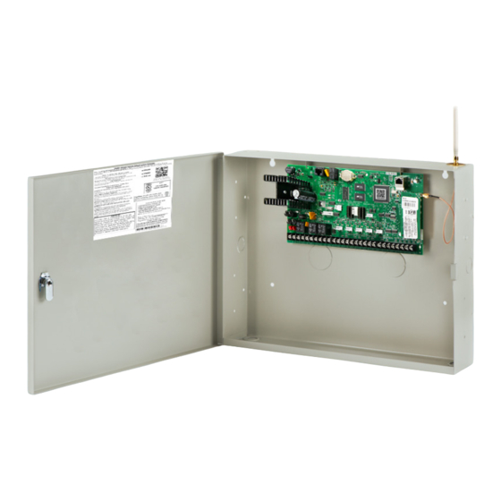
INSTALLATION Mounting the Enclosure The metal enclosure for the XR150/XR550 Series must be mounted in a secure, dry place to protect the panel from damage due to tampering or the elements. It is not necessary to remove the panel PCB when installing the enclosure. The 350A Attack Resistant enclosure is factory shipped with one knockout on the top left of the enclosure. -
Page 10: Connecting Lx-Bus™, Ax-Bus™ And Keypad Bus Devices
When planning an LX-Bus/AX-Bus and keypad bus installation, keep in mind the following information: 1. DMP recommends using 18 or 22-gauge unshielded wire for all LX-Bus/AX-Bus and keypad circuits. Do not use twisted pair or shielded wire for LX-Bus/AX-Bus and keypad bus data circuits. -
Page 11: Primary Power Supply
PRIMARY POWER SUPPLY AC Terminals 1 and 2 Connect the transformer wires to terminals 1 and 2 on the panel. Use no more than 70 ft. of 16 gauge or 40 ft. of 18 gauge wire between the transformer and the panel. Always ground the panel before applying power to any devices: The XR150/XR550 Series must be properly grounded before connecting any devices or applying power to the panel. -
Page 12: Secondary Power Supply
If you require ground fault detection, use the DMP Model 271 Ground Fault Detection Module to detect a ground fault without harming the control panel. Connect the module to a zone and the earth ground (if available) using 14 gauge wire or larger to detect a ground fault. -
Page 13: Battery Cutoff
Battery Cutoff The panel disconnects the battery any time the battery voltage drops below 10.2 VDC. This prevents battery deep discharge damage. Power Requirements During AC power failure, the XR150/XR550 Series panel and all connected auxiliary devices draw their power from the battery. - Page 14 Standby Battery Power Calculations Standby Current Alarm Current 736P POPIT Interface Module Qty _______ 25mA ______ Qty _______ 25mA ______ Radionics Popex, POPITs, Qty _______ ___mA ______ Qty _______ ___mA ______ OctoPOPITs 738A Ademco Wireless Interface Module Qty _______ x 75mA ______ Qty _______ x 75mA ______...
-
Page 15: Standby Battery Selection
Model 324/324P Wire-in 100 VA Transformer may be used with any of the battery choices listed below. For listed installations, batteries can be installed in a DMP Model 349, 350 or 352S enclosure and all wiring shall run through conduit. The enclosure shall be installed to the left of the XR150/XR550 Series enclosure to ensure Battery and AC wire separation. -
Page 16: System Components
Lightning Protection Metal Oxide Varistors and Transient Voltage Suppressors help protect against voltage surges on panel input and output circuits. Additional surge protection is available by installing the DMP 370 or 370RJ Lightning Suppressors or Model 270 Network Transient Suppression Module. -
Page 17: Bell Output
BELL OUTPUT Terminals 5 and 6 Terminal 5 supplies positive 12 VDC to power alarm bells or horns. This output can be steady, pulsed, or temporal depending upon the Bell Action specified in Bell Options. Terminal 6 is the ground reference for the bell circuit. This supervised output detects 1k Ohms or less as normal. -
Page 18: Keypad Bus
XR550 Series and 8 supervised keypads to the XR150 Series as well as multiple unsupervised keypads. In addition to DMP keypads, you can also connect any combination of zone expansion modules to the data bus up to a total of 16 devices. -
Page 19: Smoke And Glassbreak Detector Output
SMOKE AND GLASSBREAK DETECTOR OUTPUT Terminals 11 and 12 Terminal 11 supplies positive 12 VDC regulated to power 4-wire smoke detectors and other powered devices. This output can be turned off by the user for 5 seconds using the Sensor Reset User Menu option to allow latched devices to reset. -
Page 20: Protection Zones
Zone 8 voltage sensing The voltage sensing terminal measures the voltage across a 1k Ohm End-of-Line resistor to ground. Use DMP Model 311 1k Ohm resistors. Dry contact sensing devices can be used in series (normally-closed) or in parallel (normally-open) with any of the burglary protection zones. -
Page 21: Powered Zones For 2-Wire Smoke Detectors
POWERED ZONES FOR 2-WIRE SMOKE DETECTORS Terminals 25–26 and 27–28 Panel terminals 25 through 28 provide two resettable Class B, Style A, 2-wire powered zones. For programming purposes the zone numbers are 9 and 10. The maximum wire length for either zone 9 or zone 10 is 3000 feet using 18 AWG or 1000 feet using 22 AWG. The maximum voltage is 13.8 VDC and the maximum normal standby current is 1.25 mA DC. -
Page 22: Dry Contact Relay Outputs
Model 431 Output Harness Wiring The relay contacts are accessible by installing the DMP 431 Output Harness on the 6-pin OUT1-OUT2 header. OUTPUT 2 uses the top three prongs, and OUTPUT 1 uses the bottom three prongs. The wire harness and contact locations are shown below: •... -
Page 23: Annunciator Outputs
Model 300 Harness Wiring Access the open collector outputs by installing DMP 300 Harness on the 4-pin OUTPUTS header. The output locations are shown below. For listed applications, devices connected to the outputs must be located within the same room as the panel. -
Page 24: Wireless Bus Expansion
WIRELESS BUS EXPANSION Description The X-BUS Wireless Bus header provides connection for the 1100XH/1100XHE Wireless Receiver. The X-BUS provides up to 500 wireless zones numbered 500-999. Refer to the 1100XH Series Wireless Receiver Install Guide (LT-1823) for complete information. • XR150 provides up to 100 wireless zones •... -
Page 25: Lx-Bus Tm /Ax-Bus Tm Expansion
EXPANSION LX-Bus/AX-Bus Headers XR Series control panels are capable of providing zone, output, and access control expansion by connecting hardware modules to the AX/LX-Bus headers on the control panel. XR150 panels are manufactured with one LX-Bus header labeled LX500. AX-Bus operation does not apply to XR150 panels. XR550 panels are manufactured with five AX/LX-Bus headers labeled LX500-LX900. -
Page 26: Device Addressing
Device Addressing Addressable expanders and door controllers identify themselves to the control panel by their programmed address, which allows the panel to uniquely identify devices. An addressable device’s address determines which numbers the zones, outputs and door controllers will be assigned in programming. Refer to the device’s installation guide for addressing information. -
Page 27: Ethernet Connector
Figure 7: Ethernet and LEDs Network Transient Suppression The Model 270 Transient Suppression Module provides surge suppression from the Ethernet network for the protection of DMP Panels. Refer to the Model 270 Installation Sheet (LT-1316) for complete information. Condition Resistance on Zone... -
Page 28: Phone Line Rj Connector
Connect the panel to the public telephone network by installing a DMP 356 RJ Cable between the panel PHONE LINE connector and the RJ31X or RJ38X phone block. The maximum impedance is 100 Ohms. To reduce the risk of fire, use only No. 26 AWG or larger telecommunication line cord, such as DMP Model 356 Series Phone Cords. -
Page 29: Reset And Tamper Headers
30 minutes, you must reset the panel again. TAMPER Header The TAMPER header is for use with the optional DMP 306 Tamper Harness. The harness connects to one or more tamper switches mounted inside the panel enclosure to supervise against unauthorized enclosure opening or removal. Refer to the wiring diagram on the enclosure door for correct tamper switch wiring. -
Page 30: Cellular Modules
The CELL MODULE header is located to the right of the EXP Expansion Module on the right side of the circuit board and is used to connect the DMP Model 263LTE Cellular Communicator. This provides a fully supervised alarm communication path for the XR150/XR550 panel. -
Page 31: Wi-Fi Connection
WI-FI CONNECTION 763 Module to EXP Header The 763 Wi-Fi Module allows you to add Wi-Fi alarm signal communication to XR150/XR550 Series panels. The 763 connects to the 7-pin EXP header on compatible panels using the included cable and operates at 12 VDC from the panel power supply. -
Page 32: Accessory Devices
263LTE Cellular Communicator Allows you to connect the XR150/XR550 Series to the LTE network. 263LTE-FN Cellular Communicator Provides wireless communication for XR Series panels and is approved for use on FirstNet. Accessory Modules 270 Network Transient Provides transient surge protection for the ETHERNET Connector. - Page 33 Carbon monoxide detector. Interface Modules 736P Radionics™ Popit Interface Allows a Radionics™ POPIT System to interface with DMP XR150/XR550 Series panels while maintaining Radionics™ wiring. 738A Ademco Interface Allows Ademco™ 5881 wireless receivers to interface with DMP XR150/XR550 Series panels.
-
Page 34: Fcc Registration
If trouble is experienced with the Model XR150/XR550 Series, for repair or warranty information, please contact DMP at the address and telephone number listed on the back of this document. If the equipment is causing harm to the telephone network, the telephone company may request that you disconnect the equipment until the problem is resolved. -
Page 36: Certifications
A C C E S S N E T W O R K manufactured using U.S. and global 2500 North Partnership Boulevard components in Springfield, MO. Springfield, Missouri 65803-8877 © 2024 Digital Monitoring Products, Inc. 888.436.7832 | DMP.com LT-1233 1.01 24373...
Need help?
Do you have a question about the XR Series and is the answer not in the manual?
Questions and answers